Lenovo ideacentre 610s Hardware Maintenance Manual Download Page 23

Chapter 6. Hardware locations

This section provides information about the locations of your computer hardware.

Note:

The computer hardware might look slightly different from the illustrations.

Front view and rear view

Attention:

Be careful not to block any air vents on the computer. Blocked air vents can cause overheating.

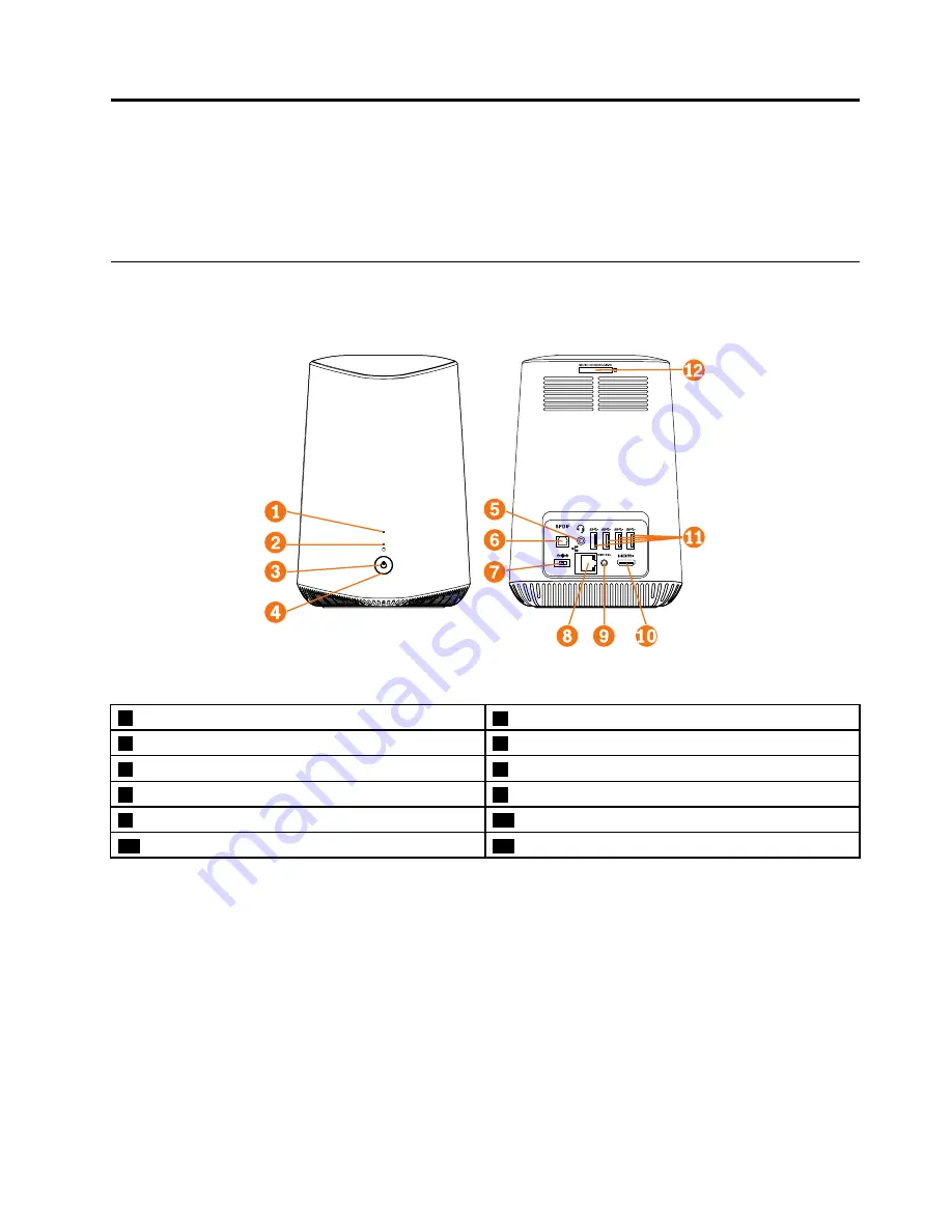
Figure 1. Front view and rear view

1

Wireless activity indicator

2

Storage drive activity indicator

3

Power indicator

4

Power button

5

Headset connector (also known as combo audio jack)

6

SPDIF-out connector

7

Power adapter connector

8

Ethernet connector

9

Wireless reset button

10

HDMI

TM

-out connector

11

USB 3.0 connectors (4)

12

Card reader slot

© Copyright Lenovo 2016

17

Summary of Contents for ideacentre 610s

Page 1: ...ideacentre 610S Hardware Maintenance Manual Machine Types 90FC 610S 02ISH Energy Star ...

Page 2: ...first Important safety information on page 1 First Edition May 2016 Copyright Lenovo 2016 LIMITED AND RESTRICTED RIGHTS NOTICE If data or software are delivered pursuant to a General Services Administration GSA contract use reproduction or disclosure is subject to restrictions set forth in Contract No GS 35F 05925 ...

Page 3: ...5 POST error codes 16 Undetermined problems 16 Chapter 6 Hardware locations 17 Front view and rear view 17 Major FRUs and CRUs 18 Parts on the main boards 20 Chapter 7 Installing or replacing hardware 23 Handling static sensitive devices 23 Installing or replacing hardware 23 Removing the computer covers 23 Replacing the I O board shield 26 Replacing the I O board 27 Replacing the discrete graphic...

Page 4: ...ii ideacentre 610S Hardware Maintenance Manual ...

Page 5: ...troubleshoot problems Important This manual is intended only for trained service technicians who are familiar with Lenovo computers Use this manual along with the advanced diagnostic tests to troubleshoot problems effectively Before servicing a Lenovo computer be sure to read and understand Chapter 1 Read this first Important safety information on page 1 Copyright Lenovo 2016 iii ...

Page 6: ...iv ideacentre 610S Hardware Maintenance Manual ...

Page 7: ...om areas that people may walk through to ensure no one trips over it Do not wear loose clothing that can be trapped in the moving parts of a machine Ensure that your sleeves are fastened or rolled up above your elbows If your hair is long tie or fasten it back Insert the ends of your necktie or scarf inside clothing or fasten it with a non conductive clip approximately 8 centimeters 3 inches from ...

Page 8: ...ere must be a complete circuit to cause electrical shock By observing the above rule you may prevent a current from passing through your body When using a tester set the controls correctly and use the approved probe leads and accessories for that tester Stand on suitable rubber mats obtained locally if necessary to insulate you from grounds such as metal floor strips and machine frames Observe the...

Page 9: ...ower cord 3 Check the power cord for a A third wire ground connector in good condition Use a meter to measure third wire ground continuity for 0 1 ohm or less between the external ground pin and frame ground b The power cord should be the appropriate type as specified in the parts listings c Insulation must not be frayed or worn 4 Remove the cover 5 Check for any obvious alterations Use good judgm...

Page 10: ...lectrical grounding of the computer is required for operator safety and correct system function Proper grounding of the electrical outlet can be verified by a certified electrician Safety notices The CAUTION and DANGER safety notices in this section are provided in the language of English DANGER Electrical current from power telephone and communication cables is hazardous To avoid a shock hazard D...

Page 11: ...mmerse in water Heat to more than 100 C 212 F Repair or disassemble Dispose of the battery as required by local ordinances or regulations CAUTION When laser products such as CD ROMs DVD ROM drives fiber optic devices or transmitters are installed note the following Do not remove the covers Removing the covers of the laser product could result in exposure to hazardous laser radiation There are no s...

Page 12: ...do not turn off the electrical current supplied to the device The device also might have more than one power cord To remove all electrical current from the device ensure that all power cords are disconnected from the power source 1 2 CAUTION Do not place any object weighing more than 82 kg 180 lbs on top of rack mounted devices 6 ideacentre 610S Hardware Maintenance Manual ...

Page 13: ... C 40 F to 60 C 140 F Storage without package From 10 C 14 F to 60 C 140 F Humidity Operating 20 80 non condensing Storage 20 90 non condensing Altitude Operating From 15 2 m 50 ft to 3048 m 10 000 ft Storage From 15 2 m 50 ft to 10 668 m 35 000 ft Electrical input Input voltage From 100 V ac to 240 V ac Input frequency 50 60 Hz Copyright Lenovo 2016 7 ...

Page 14: ...8 ideacentre 610S Hardware Maintenance Manual ...

Page 15: ...ocedure to help determine the cause of the problem 1 Power off the computer and all external devices 2 Check all cables and power cords 3 Set all display controls to the middle position 4 Power on all external devices 5 Power on the computer Look for error codes displayed Look for readable instructions or a main menu on the display If you did not receive the correct response proceed to step 6 If y...

Page 16: ...10 ideacentre 610S Hardware Maintenance Manual ...

Page 17: ...Enabling or disabling a device This section provides information about how to enable or disable user access to hardware devices such as USB connectors or storage drives To enable or disable a device do the following 1 Start the Setup Utility program See Starting the Setup Utility program on page 11 2 Select Devices 3 Select the device you want to enable or disable and press Enter 4 Select the desi...

Page 18: ... characters For security reasons it is recommended to use a strong password that cannot be easily compromised Note The Setup Utility program passwords are not case sensitive To set a strong password consider the following guidelines Have at least eight characters in length Contain at least one alphabetic character and one numeric character Not be your name or your user name Not be a common word or...

Page 19: ...on or turn on the computer Then insert the disc into the optical drive If the storage device is an external device other than a disc connect the storage device to the computer 2 Turn on or restart the computer Before Windows starts up repeatedly press and release the F12 key until Startup Device Menu is displayed Note For some keyboards you might need to press Fn F12 to display Startup Device Menu...

Page 20: ...14 ideacentre 610S Hardware Maintenance Manual ...

Page 21: ...d disk drive boot error A hard disk drive boot error can be caused by the following Error FRU Action The startup drive is not included in the boot sequence configuration Check the configuration and ensure the startup drive is in the boot sequence No operating system is installed on the boot drive Install an operating system on the boot drive The boot sector on the startup drive is corrupted The dr...

Page 22: ... Startup and set the option to Enabled The BIOS then ignores the missing keyboard during POST Reboot and Select proper Boot device or Insert Boot Media in selected Boot device The BIOS was unable to find a suitable boot device Make sure the boot drive is properly connected to the computer Make sure you have bootable media in the boot device Undetermined problems 1 Power off the computer 2 Remove o...

Page 23: ...block any air vents on the computer Blocked air vents can cause overheating Figure 1 Front view and rear view 1 Wireless activity indicator 2 Storage drive activity indicator 3 Power indicator 4 Power button 5 Headset connector also known as combo audio jack 6 SPDIF out connector 7 Power adapter connector 8 Ethernet connector 9 Wireless reset button 10 HDMITM out connector 11 USB 3 0 connectors 4 ...

Page 24: ...Major FRUs and CRUs Note Depending on your computer model some of the following components might not be available Figure 2 Major FRUs and CRUs 18 ideacentre 610S Hardware Maintenance Manual ...

Page 25: ...scription Self service CRU Optional service CRU 1 Top cover No No 2 Body cover No No 3 Wi Fi antennas 2 No No 4 Chassis No No 5 Storage drive board No No 6 Storage drive board shield No No 7 Wireless card No No 8 Power button board No No 9 M 2 solid state drive No No 10 2 5 inch storage drive bracket No No 11 2 5 inch storage drive No No 12 Bottom fan No No 13 Memory module No No 14 Coin cell batt...

Page 26: ...yed on the following figure but not introduced in the following table see Front view and rear view on page 17 Figure 3 Parts on the I O board 1 Power connector connected to the discrete graphics card 2 Pogo pin board connector 3 I O connector connected to the system board 4 HDMI connector connected to the system board 20 ideacentre 610S Hardware Maintenance Manual ...

Page 27: ...5 Memory slot 6 Wireless card connector 7 Power button board connector 8 HDMI connector connected to the I O board 9 I O connector connected to the I O board 10 PCI Express connector connected to the discrete graphics card 11 Power connector connected to the discrete graphics card 12 Coin cell battery 13 Bottom fan connector 14 Microprocessor socket Chapter 6 Hardware locations 21 ...

Page 28: ... board Figure 5 Parts on the storage drive board 1 M 2 solid state drive slot 2 SATA connector connected to the system board 3 SATA connector connected to the 2 5 inch storage drive 22 ideacentre 610S Hardware Maintenance Manual ...

Page 29: ...n possible remove the new part from the static protective package and install it directly in the computer without setting the part down When this is not possible place the static protective package that the part came in on a smooth level surface and place the part on the package Do not place the part on the computer cover or other metal surface Installing or replacing hardware This section provide...

Page 30: ...he drives and turn off all connected devices and the computer Then disconnect all power cords from electrical outlets and all cables that are connected to the computer 2 Unlock all locking devices that secure the computer covers 3 If the computer is shipped with the projector remove the top cover first as shown Figure 6 Removing the top cover 24 ideacentre 610S Hardware Maintenance Manual ...

Page 31: ...4 Remove the bottom cover as shown Figure 7 Removing the bottom cover 5 Remove the rear I O cover as shown Figure 8 Removing the rear I O cover Chapter 7 Installing or replacing hardware 25 ...

Page 32: ...his first Important safety information on page 1 To replace the I O board shield do the following 1 Remove all media from the drives and turn off all connected devices and the computer Then disconnect all power cords from electrical outlets and all cables that are connected to the computer 2 Remove the computer covers See Removing the computer covers on page 23 26 ideacentre 610S Hardware Maintena...

Page 33: ... or attempt any repair before reading and understanding the Chapter 1 Read this first Important safety information on page 1 To replace the I O board do the following 1 Remove all media from the drives and turn off all connected devices and the computer Then disconnect all power cords from electrical outlets and all cables that are connected to the computer 2 Remove the computer covers See Removin...

Page 34: ...e main boards on page 20 9 Reinstall the power connecting board 10 Reinstall the I O board shield See Replacing the I O board shield on page 26 What to do next To work with another piece of hardware go to the appropriate section To complete the installation or replacement go to Completing the parts replacement on page 47 Replacing the discrete graphics card Attention Do not open your computer or a...

Page 35: ... 13 Removing the power connecting board 5 Record the cable routing and cable connections and then disconnect all cables from the discrete graphics card 6 Remove the discrete graphics card as shown Note Do not touch the thermal grease while handling the discrete graphics card Figure 14 Removing the discrete graphics card 7 Install the new discrete graphics card 8 Route all the cables that you disco...

Page 36: ...the power button board 4 Remove the power button board as shown Figure 15 Removing the power button board 5 Install the new power button board 6 Connect the power button board cable to the new power button board What to do next To work with another piece of hardware go to the appropriate section To complete the installation or replacement go to Completing the parts replacement on page 47 Replacing...

Page 37: ...empt any repair before reading and understanding the Chapter 1 Read this first Important safety information on page 1 To replace the system board shield and storage drive board shield do the following 1 Remove all media from the drives and turn off all connected devices and the computer Then disconnect all power cords from electrical outlets and all cables that are connected to the computer 2 Remo...

Page 38: ...attempt any repair before reading and understanding the Chapter 1 Read this first Important safety information on page 1 To replace the storage drive refer to one of the following topics Replacing the 2 5 inch storage drive on page 32 Replacing the M 2 solid state drive on page 33 Replacing the 2 5 inch storage drive To replace the 2 5 inch storage drive do the following 1 Remove all media from th...

Page 39: ...ce of hardware go to the appropriate section To complete the installation or replacement go to Completing the parts replacement on page 47 Replacing the M 2 solid state drive To replace the M 2 solid state drive do the following 1 Remove all media from the drives and turn off all connected devices and the computer Then disconnect all power cords from electrical outlets and all cables that are conn...

Page 40: ... and understanding the Chapter 1 Read this first Important safety information on page 1 To replace the storage drive board do the following 1 Remove all media from the drives and turn off all connected devices and the computer Then disconnect all power cords from electrical outlets and all cables that are connected to the computer 2 Remove the computer covers See Removing the computer covers on pa...

Page 41: ...See Replacing the power button board on page 30 16 Reinstall the I O board shield See Replacing the I O board shield on page 26 What to do next To work with another piece of hardware go to the appropriate section To complete the installation or replacement go to Completing the parts replacement on page 47 Replacing the card reader Attention Do not open your computer or attempt any repair before re...

Page 42: ...move all media from the drives and turn off all connected devices and the computer Then disconnect all power cords from electrical outlets and all cables that are connected to the computer 2 Remove the computer covers See Removing the computer covers on page 23 3 Remove the I O board shield See Replacing the I O board shield on page 26 4 Remove the power button board See Replacing the power button...

Page 43: ...l the new pogo pin board 16 Reinstall the card reader See Replacing the card reader on page 35 17 Reinstall the storage drive board shield and the system board shield See Replacing the system board shield and the storage drive board shield on page 31 18 Reinstall the wireless card See Replacing the wireless card on page 30 19 Reinstall the power button board See Replacing the power button board on...

Page 44: ... 8 Lift the pogo pin board and the top fan See Replacing the pogo pin board and the top fan on page 36 9 Disconnect the Wi Fi antenna cables from the Wi Fi card 10 Remove the Wi Fi antennas as shown Figure 24 Removing the Wi Fi antennas 11 Route the new Wi Fi antenna cables and then connect them to the Wi Fi card 12 Install the new Wi Fi antennas 13 Reinstall the top fan and the pogo pin board See...

Page 45: ...he Wi Fi antenna cables to the new Wi Fi card 11 Reinstall the storage drive board shield and the system board shield See Replacing the system board shield and the storage drive board shield on page 31 12 Reinstall the wireless card See Replacing the wireless card on page 30 13 Reinstall the power button board See Replacing the power button board on page 30 14 Reinstall the I O board shield See Re...

Page 46: ...ompleting the parts replacement on page 47 Replacing the system board Attention Do not open your computer or attempt any repair before reading and understanding the Chapter 1 Read this first Important safety information on page 1 To replace the system board do the following 1 Remove all media from the drives and turn off all connected devices and the computer Then disconnect all power cords from e...

Page 47: ...y the edges of the microprocessor Do not touch the gold contacts on the bottom Do not touch the thermal grease while handling the microprocessor Do not drop anything onto the microprocessor socket while it is exposed The socket pins must be kept as clean as possible Figure 28 Removing the microprocessor 11 Install the microprocessor onto the new system board 12 Install the new system board Chapter...

Page 48: ...curely 4 Follow any additional instructions that are included with the replacement part you received Replacing the coin cell battery Attention Do not open your computer or attempt any repair before reading and understanding the Chapter 1 Read this first Important safety information on page 1 Your computer has a special type of memory that maintains the date time and settings for built in features ...

Page 49: ...after replacing the coin cell battery 17 Use the Setup Utility program to set the date time and any passwords See Chapter 4 Using the Setup Utility program on page 11 Replacing the microprocessor Attention Do not open your computer or attempt any repair before reading and understanding the Chapter 1 Read this first Important safety information on page 1 CAUTION The heat sinks might be very hot Bef...

Page 50: ...ge drive board shield and the system board shield See Replacing the system board shield and the storage drive board shield on page 31 12 Reinstall the wireless card See Replacing the wireless card on page 30 13 Reinstall the power button board See Replacing the power button board on page 30 14 Reinstall the I O board shield See Replacing the I O board shield on page 26 What to do next To work with...

Page 51: ... graphics card See Replacing the discrete graphics card on page 28 6 Remove the power button board See Replacing the power button board on page 30 7 Remove the wireless card See Replacing the wireless card on page 30 8 Remove the system board shield and the storage drive board shield See Replacing the system board shield and the storage drive board shield on page 31 9 Remove the system board See R...

Page 52: ...ng the I O board on page 27 20 Reinstall the I O board shield See Replacing the I O board shield on page 26 What to do next To work with another piece of hardware go to the appropriate section To complete the installation or replacement go to Completing the parts replacement on page 47 Replacing the bottom fan Attention Do not open your computer or attempt any repair before reading and understandi...

Page 53: ... 30 17 Reinstall the power button board See Replacing the power button board on page 30 18 Reinstall the discrete graphics card See Replacing the discrete graphics card on page 28 19 Reinstall the I O board See Replacing the I O board on page 27 20 Reinstall the I O board shield See Replacing the I O board shield on page 26 What to do next To work with another piece of hardware go to the appropria...

Page 54: ...ck the computer 8 Reconnect the external cables and power cords to the corresponding connectors on the computer 9 Depending on the parts you installed or replaced you might need to confirm the updated information See Chapter 4 Using the Setup Utility program on page 11 10 If a newly installed hardware component does not work normally update the device driver 48 ideacentre 610S Hardware Maintenance...

Page 55: ...35 N MB H110 DDR4 For C_TINY NO DPK 00XK028 N MB H110 DDR4 For C_TINY WIN DPK Cable FRU P N CRU ID Description 00XL107 N Fru SSD FPC cable 00XL106 N Fru IO FPC cable 00XL105 N Fru GFX FPC cable 00XL104 N Fru HDMI FPC Cable 00XL113 N Fru Power Switch FFC cable 00XL114 N Fru 2000mm HDMI A M HDMI A M cable 00XL112 N Fru WiHD FPC cable 00XL103 N Fru POGO wPCBA Cable 00XL108 N Fru Power _Led cable 00XL...

Page 56: ... CN 1M 3P NON LH 00XL086 1 Fru LINECORD IL 1M 3P NON LH 00XL092 1 Fru LINECORD TW 1M 3P NON LH 00XL061 1 Fru LINECORD BR 1M 3P NON LH 00XL053 1 Fru US CA 1M 3P NON LH 00XL066 1 Fru LINECORD DK 1M 3P NON LH 00XL074 1 Fru LINECORD IT 1M 3P NON LH 00XL057 1 Fru LINECORD AR 1M 3P NON LH 00XL096 1 Fru LINECORD IN 1M 3P NON LH 00XL082 1 Fru LINECORD ZA 1M 3P NON LH 00XL052 1 Fru US CA 1M 3P NON LH 00XL0...

Page 57: ...LH 00XL083 1 Fru LINECORD ZA 1M 3P NON LH 00XL058 1 Fru LINECORD AR 1M 3P NON LH 00XL072 1 Fru LINECORD IT 1M 3P NON LH 00XL002 1 Fru JP Anti TR 1M 2P NON LH 00XL060 1 Fru LINECORD BR 1M 3P NON LH Mechanical FRU P N CRU ID Description 01EF247 N ASSY COVER FOR PROJECTOR 01EF202 N ASSY C T_M_HDD CAGE 01EF206 1 ASSY C T_P_BOTTOM_COVER 01EF248 N ASSY COVER FOR NON PROJECTOR 01EF203 N ASSY C T_P_MAIN C...

Page 58: ... Intel Pentium G4400T 2 9GHz 35W Solid state drive FRU P N CRU ID Description 00JT086 N 128G M 2 2280 SATA6G LTON STD 00JT008 N 128G M 2 2280 SATA6G SAMSG STD Wireless FRU P N CRU ID Description 00JT471 N Wireless CMB LTN NFA344 V2 00JT507 N Wireless CMB IN 3165 ac Ind 00JT506 N Wireless CMB IN 8260 NV Ind 00JT454 N Wireless CMB LTN 8821AE 00JT480 N Wireless CMB IN 8260 ac NV 00JT497 N Wireless CM...

Page 59: ...em is allowed to control the power management features of the computer and the settings for Advanced Power Management APM BIOS mode is ignored Not all operating systems support ACPI BIOS mode Automatic Power On features The Automatic Power On features within the Power Management menu allow you to enable and disable features that turn on the computer automatically Wake Up on Alarm You can specify a...

Page 60: ...54 ideacentre 610S Hardware Maintenance Manual ...

Page 61: ...enovo in the United States other countries or both ideacentre Lenovo The Lenovo logo Windows is a trademark of the Microsoft group of companies Other company product or service names may be trademarks or service marks of others Copyright Lenovo 2016 1 ...

Page 62: ...2 ideacentre 610S Hardware Maintenance Manual ...

Page 63: ......

Page 64: ......

Reviews: