Procedure
Step 1. Touch the static-protective package that contains the new component to any unpainted surface on
the outside of the server. Then, take the new component of the package and place it on a static-
protective surface.
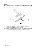
Step 2. Install the rearwall brackets.
a. Align the rearwall bracket with the chassis rearwall, and insert the bracket into place.
b. Install the screws to secure the rearwall bracket.
Note:
The illustrations show installing the rearwall bracket on the right of the configuration with 7
PCIe slots. The procedure is the same for installing other rearwall brackets.
Figure 46. Rearwall bracket installation (on the right of the configuration with 7 PCIe slots)
After you finish
1. Install a rear drive cage or riser assemblies.
• “Install a riser card” on page 83
• “Install the rear 2.5-inch drive cage” on page 62
• “Install the rear 3.5-inch drive cage” on page 67
2. Complete the parts replacement. See “Complete the parts replacement” on page 113.
Hot–swap power supply unit replacement
Use this information to remove and install a hot-swap power supply unit.
Safety precautions
The section lists safety precautions that apply to AC and DC power supply units respectively. Understand
and apply the safety precautions before removing or installing a power supply unit.
.
Hardware replacement procedures
71
Summary of Contents for HR650X V2
Page 1: ...HR650X V2 User Guide Machine Types 7D4D ...
Page 8: ......
Page 14: ...6 HR650X V2 User Guide ...
Page 30: ...22 HR650X V2 User Guide ...
Page 122: ...114 HR650X V2 User Guide ...
Page 152: ...144 HR650X V2 User Guide ...
Page 176: ...168 HR650X V2 User Guide ...
Page 182: ...174 HR650X V2 User Guide ...
Page 186: ...178 HR650X V2 User Guide ...
Page 190: ...182 HR650X V2 User Guide ...
Page 191: ......
Page 192: ......


