• Thermal grease
• RFID tag (required only if the compute node came with a RFID tag attached to the bezel)
Important:
When you replace the system board, you must update the compute node with the latest firmware
or restore the preexisting firmware. Make sure that you have the latest firmware or a copy of the preexisting
firmware before you proceed. See “Updating firmware and device drivers” on page 21 for more information.
See “System-board layouts” on page 17 for more information about the locations of the connectors,
jumpers, and LEDs on the system board.
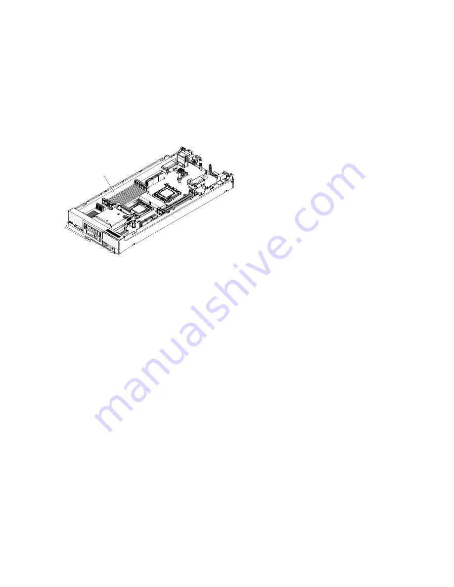
To remove the system-board assembly, complete the following
steps:
000
000
000
000
000
0000000000
0000000000
0000000000
0000000000
0000000000
0000000000
0000000000
System-board
assembly
Step 1.
Remove the cover (see “Removing the compute node cover” on page 643).
Step 2.
Remove all of the installed components in the following list from the system-board assembly; then,
place them on a static-protective surface or install them on the new system-board assembly.
• DIMMs and air baffles (see “Removing a DIMM” on page 652).
• I/O expansion adapters (see “Removing an I/O expansion adapter” on page 666).
• Fabric connector. (see “Removing a fabric connector” on page 659).
• ServeRAID controller. (see “Removing a ServeRAID controller” on page 664).
• Hard disk drives and hard disk drive bay fillers (see “Removing a hot-swap hard disk drive”
• Microprocessors, heat sinks, and microprocessor heat-sink fillers. Use the microprocessor
installation tool that comes with the replacement microprocessor to remove each microprocessor
from the system-board assembly and install each one immediately in the new system-board
assembly (see “Removing a microprocessor and heat sink” on page 675 and “Installing a
microprocessor and heat sink” on page 678).
• Hard disk drive backplane (see “Removing the hard disk drive backplane” on page 661).
Step 3.
If you are replacing the old system-board assembly with a new system-board assembly, carefully
remove the bezel from the old system-board assembly and install it on the new system-board
assembly (see “Removing the bezel” on page 648 and “Installing the bezel” on page 649). If the old
bezel will not attach securely to the new system board, remove the Tag from the lower right corner
of the old bezel and install it on the lower right corner of the new bezel that shipped with the new
system-board assembly; then, install the new bezel on the new system-board assembly.
If you are instructed to return the system-board assembly, follow all packaging instructions, and use any
packaging materials for shipping that are supplied to you.
Installing the system-board assembly
Use this information to install the system-board assembly.
684
Flex System x220 Compute Node Installation and Service Guide
Summary of Contents for Flex System x220
Page 1: ...Flex System x220 Compute Node Installation and Service Guide Machine Types 7906 2585 ...
Page 50: ...42 Flex System x220 Compute Node Installation and Service Guide ...
Page 54: ...46 Flex System x220 Compute Node Installation and Service Guide ...
Page 68: ...60 Flex System x220 Compute Node Installation and Service Guide ...
Page 644: ...636 Flex System x220 Compute Node Installation and Service Guide ...
Page 698: ...690 Flex System x220 Compute Node Installation and Service Guide ...
Page 705: ...Taiwan BSMI RoHS declaration Appendix B Notices 697 ...
Page 706: ...698 Flex System x220 Compute Node Installation and Service Guide ...
Page 713: ......
Page 714: ...Part Number 00YJ297 Printed in China 1P P N 00YJ297 1P00YJ297 ...


