additional drive in hard disk drive bay 1. The compute node supports using RAID 0 or RAID 1 when two
hard disk drives of the same interface type are installed. See “Configuring a RAID array” on page 33 for
information about RAID configuration.
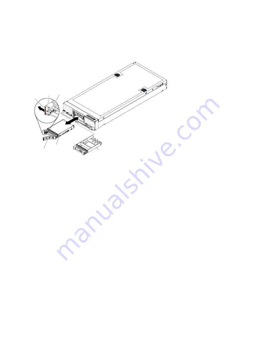
To install a hot-swap hard disk drive or hard disk drive bay filler, complete the following steps.
0000
0000
0000
0000
00000000000
00000000000
00000000000
00000000000
00000000000
00000000000
Release
latch
Hard disk
drive
assembly
Hard disk
drive bay filler
Drive
handle
Activity
LED
(green)
Error
LED
(amber)
Step 1.
Identify the hard disk drive bay (hard disk drive bay 0 or hard disk drive bay 1) in which you plan to
install the hot-swap hard disk drive.
Step 2.
If a hard disk drive bay filler is installed, remove it from the compute node by pulling the release
lever and sliding the filler away from the compute node.
Step 3.
Touch the static-protective package that contains the hot-swap hard disk drive to any
unpainted
metal surface on the Flex System chassis or any
unpainted
metal surface on any other grounded
rack component; then, remove the drive from the package.
Step 4.
Open the release lever on the drive and slide the drive into the bay until it is firmly seated in the
connector.
Step 5.
Lock the drive into place by closing the release lever.
Step 6.
Check the hard disk drive status LEDs to make sure that the drive is operating correctly.
See “Configuring a RAID array” on page 33 for information about SAS RAID configuration.
Removing a ServeRAID controller
Use this information to remove a ServeRAID controller.
When the ServeRAID controller is removed, software RAID is not supported. The compute node does not
support downgrading to the software RAID function from the hardware RAID configuration.
Before you remove the ServeRAID controller, complete the following steps:
1. Read “Safety” on page iii and “Installation guidelines” on page 637.
2. If the compute node is installed in an Flex System chassis, remove it (see “Removing a compute node
from a chassis” on page 639 for instructions).
3. Carefully lay the compute node on a flat, static-protective surface, orienting the compute node with
the bezel pointing toward you.
664
Flex System x220 Compute Node Installation and Service Guide
Summary of Contents for Flex System x220
Page 1: ...Flex System x220 Compute Node Installation and Service Guide Machine Types 7906 2585 ...
Page 50: ...42 Flex System x220 Compute Node Installation and Service Guide ...
Page 54: ...46 Flex System x220 Compute Node Installation and Service Guide ...
Page 68: ...60 Flex System x220 Compute Node Installation and Service Guide ...
Page 644: ...636 Flex System x220 Compute Node Installation and Service Guide ...
Page 698: ...690 Flex System x220 Compute Node Installation and Service Guide ...
Page 705: ...Taiwan BSMI RoHS declaration Appendix B Notices 697 ...
Page 706: ...698 Flex System x220 Compute Node Installation and Service Guide ...
Page 713: ......
Page 714: ...Part Number 00YJ297 Printed in China 1P P N 00YJ297 1P00YJ297 ...


