


Note:
Noise from the ac power adapter does not always indicate a defect.
Checking operational charging
To check whether the battery charges properly during operation, use a discharged battery pack or a battery
pack that has less than 50% of the total power remaining when installed in the computer.
Perform operational charging. If the battery status indicator or icon does not turn on, remove the battery
pack and let it return to room temperature. Reinstall the battery pack. If the charge indicator or icon still does
not turn on, replace the battery pack.
If the charge indicator still does not turn on, replace the system board. Then reinstall the battery pack. If it is
still not charged, go to the next section.
Checking the battery pack
Battery charging does not start until the power meter shows that less than 95% of the total power remains;
under this condition the battery pack can charge to 100% of its capacity. This protects the battery pack from
being overcharged or from having a shortened life.
To check your battery, move your cursor to the power meter icon in the icon tray of the Windows taskbar and
wait for a moment (but do not click it), and the percentage of battery power remaining is displayed. To get
detailed information about the battery, double-click the power meter icon.
Note:
If the battery pack becomes hot, it may not be able to be charged. Remove it from the computer and
leave it at room temperature for a while. After it cools down, reinstall and recharge it.
To check the battery pack, do the following:
1. Power off the computer.
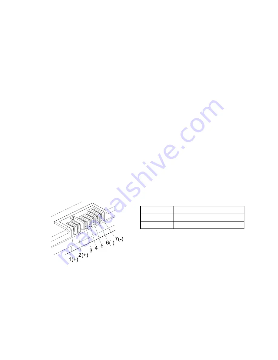
2. Remove the battery pack and measure the voltage between battery terminals 1 (+) and 7 (-). See the
following figure:
Terminal
Voltage (V dc)
1
+ 0 to + 14
7
Ground (-)
1(+)
2(+)
3
4
5
6(-)
7(-)
3. If the voltage is less than +11.0 V dc, the battery pack has been discharged.
Note:
Recharging will take at least 3 hours, even if the indicator does not turn on.
If the voltage is still less than +11.0 V dc after recharging, replace the battery.
4. If the voltage is more than +11.0 V dc, measure the resistance between battery terminals 5 and 7.
The resistance must be 4 to 30 K Ω.
If the resistance is not correct, replace the battery pack. If the resistance is correct, replace the system
board.
Chapter 3
.
General checkout
31
Summary of Contents for B580
Page 1: ...Hardware Maintenance Manual Lenovo B580 ...
Page 4: ...ii Hardware Maintenance Manual ...
Page 6: ...iv Hardware Maintenance Manual ...
Page 11: ...DANGER DANGER DANGER DANGER DANGER Chapter 1 Safety information 5 ...
Page 12: ...DANGER 6 Hardware Maintenance Manual ...
Page 13: ...Chapter 1 Safety information 7 ...
Page 14: ...PERIGO PERIGO PERIGO PERIGO PERIGO PERIGO 8 Hardware Maintenance Manual ...
Page 15: ...PERIGO PERIGO DANGER DANGER DANGER Chapter 1 Safety information 9 ...
Page 16: ...DANGER DANGER DANGER DANGER DANGER VORSICHT 10 Hardware Maintenance Manual ...
Page 17: ...VORSICHT VORSICHT VORSICHT VORSICHT Chapter 1 Safety information 11 ...
Page 18: ...VORSICHT VORSICHT VORSICHT 12 Hardware Maintenance Manual ...
Page 19: ...Chapter 1 Safety information 13 ...
Page 20: ...14 Hardware Maintenance Manual ...
Page 21: ...Chapter 1 Safety information 15 ...
Page 22: ...16 Hardware Maintenance Manual ...
Page 23: ...Chapter 1 Safety information 17 ...
Page 24: ...18 Hardware Maintenance Manual ...
Page 26: ...20 Hardware Maintenance Manual ...
Page 27: ...Chapter 1 Safety information 21 ...
Page 28: ...22 Hardware Maintenance Manual ...
Page 29: ...Chapter 1 Safety information 23 ...
Page 30: ...24 Hardware Maintenance Manual ...
Page 31: ...Chapter 1 Safety information 25 ...
Page 32: ...26 Hardware Maintenance Manual ...
Page 38: ...32 Hardware Maintenance Manual ...
Page 42: ...36 Hardware Maintenance Manual ...
Page 46: ...40 Hardware Maintenance Manual ...
Page 48: ...42 Hardware Maintenance Manual ...
Page 100: ...94 Hardware Maintenance Manual ...
Page 103: ......
Page 104: ......


