background image

Lenovo B575

45

1090 Keyboard bezel

For access, remove these FRUs in order:
• “1010 Battery pack” on page 34
• “1030 Hard disk drive(HDD)/Memory/Mini PCI Express Card slot 

compartment cover” on page 36

• “1050 Optical drive” on page 38
• “1080 Keyboard” on page 42

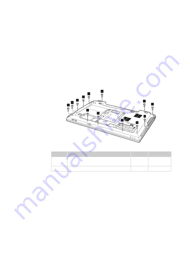
Figure 9. Removal steps of keyboard bezel

Remove ten screws 

 and three screws 

 on the bottom.

Step

Screw (quantity)

Color

Torque

M2.5 × 8 mm, flat-head, nylok-coated 
(10)

Black

2.5 kgfcm

M2 × 2.5 mm, flat-head, nylok-coated (3) White

1.5 kgfcm

a

b

1

1

1

1

1

1

1

1

1

2

2

2

1

a

b

Summary of Contents for B575

Page 1: ...Lenovo B575 Hardware Maintenance Manual ...

Page 2: ...eveloped exclusively at private expense and are sold to governmental entities as commercial items as defined by 48 C F R 2 101 with limited and restricted rights to use reproduction and disclosure LIMITED AND RESTRICTED RIGHTS NOTICE If products data computer software or services are delivered pursuant a General Services Administration GSA contract use reproduction or disclo sure is subject to res...

Page 3: ... password 24 Supervisor password 24 Power management 25 Screen blank mode 25 Sleep standby mode 25 Hibernation mode 26 Lenovo B575 27 Specifications 27 Status indicators 29 Fn key combinations 31 FRU replacement notices 32 Screw notices 32 Removing and replacing an FRU 33 1010 Battery pack 34 1020 Dummy card 35 1030 Hard disk drive HDD Memory Mini PCI Express Card slot compartment cover 36 1040 Ha...

Page 4: ...y information required for servicing computers The product specific section includes service reference and product specific parts information About this manual Important This manual is intended only for trained servicers who are familiar with Lenovo products Use this manual to troubleshoot problems effectively Before servicing a Lenovo product make sure to read all the information under Safety inf...

Page 5: ...ervice a Lenovo computer General safety on page 2 Electrical safety on page 3 Safety inspection guide on page 5 Handling devices that are sensitive to electrostatic discharge on page 6 Grounding requirements on page 6 Safety notices multilingual translations on page 7 Laser compliance statement on page 14 Safety information ...

Page 6: ...rom all personnel while you are servicing the machine Keep your toolcase away from walk areas so that other people will not trip it over Do not wear loose clothing that can be trapped in the moving parts of the machine Make sure that your sleeves are fastened or rolled up above your elbows If your hair is long fasten it Insert the ends of your necktie or scarf inside clothing or fasten it with the...

Page 7: ... Attention An electrical shock can occur only when there is a complete circuit By observing the above rule you may prevent a current from passing through your body When using testers set the controls correctly and use the approved probe leads and accessories for that tester Stand on suitable rubber mats obtained locally if necessary to insulate you from grounds such as metal floor strips and machi...

Page 8: ... a plastic dental mirror The surface is conductive such touching can cause personal injury and machine damage Do not service the following parts with the power on when they are removed from their normal operating places in a machine Power supply units Pumps Blowers and fans Motor generators and similar units This practice ensures correct grounding of the units If an electrical accident occurs Caut...

Page 9: ... determine whether there are any potential unsafe conditions use the following checklist at the beginning of every service task Begin the checks with the power off and the power cord disconnected Checklist 1 Check exterior covers for damage loose broken or sharp edges 2 Turn off the computer Disconnect the power cord 3 Check the power cord for a A third wire ground connector in good condition Use ...

Page 10: ...t is especially useful when handling ESD sensitive devices Select a grounding system such as those listed below to provide protection that meets the specific service requirement Attach the ESD ground clip to any frame ground ground braid or green wire ground When working on a double insulated or battery operated system use an ESD common ground or reference point You can use coax or connector outsi...

Page 11: ... Austausch der Computer wieder angeschlossen wird muß sichergestellt werden daß keine Schrauben Federn oder andere Kleinteile fehlen oder im Gehäuse vergessen wurden Der Computer muß geschüttelt und auf Klappergeräusche geprüft werden Metallteile oder splitter können Kurzschlüsse erzeugen Prima di accendere l elaboratore dopo che é stata effettuata la sostituzione di una FRU accertarsi che tutte l...

Page 12: ...n Sie darf nicht zerlegt wiederaufgeladen kurzgeschlossen oder Feuer oder Wasser ausgesetzt werden Bei der Entsorgung die örtlichen Bestimmungen für Sondermüll beachten Beim Ersetzen der Bereitschafts oder Systembatterie nur Batterien des Typs verwenden der in der Ersatzteilliste aufgeführt ist Der Einsatz falscher Batterien kann zu Entzündung oder Explosion führen Alcune batterie di riserva conte...

Page 13: ...eschlossen oder Feuer oder Wasser ausgesetzt werden Bei der Entsorgung die örtlichen Bestimmungen für Sondermüll beachten Beim Ersetzen der Batterie nur Batterien des Typs verwenden der in der Ersatzteilliste aufgeführt ist Der Einsatz falscher Batterien kann zu Entzündung oder Explosion führen La batteria contiene piccole quantità di nichel Non smontarla gettarla nel fuoco o nell acqua né cortoci...

Page 14: ...s Typs dürfen nicht aufgeladen zerlegt über 100 C erhitzt oder verbrannt werden Auch darf ihr Inhalt nicht mit Wasser in Verbindung gebracht oder der zur richtigen Polung angebrachte Verbindungsstecker entfernt werden Bei der Entsorgung die örtlichen Bestimmungen für Sondermüll beachten Beim Ersetzen der Batterie nur Batterien des Typs verwenden der in der Ersatzteilliste aufgeführt ist Der Einsat...

Page 15: ...ten Der LCD Bildschirm besteht aus Glas und kann zerbrechen wenn er unsachgemäß behandelt wird oder der Computer auf den Boden fällt Wenn der Bildschirm beschädigt ist und die darin befindliche Flüssigkeit in Kontakt mit Haut und Augen gerät sollten die betroffenen Stellen mindestens 15 Minuten mit Wasser abgespült und bei Beschwerden anschließend ein Arzt aufgesucht werden Nel caso che caso l LCD...

Page 16: ...tery can produce enough current to burn personnel or combustible materials Bien que le voltage des batteries principales soit peu élevé le court circuit ou la mise à la masse d une batterie peut produire suffisamment de courant pour brûler des matériaux combustibles ou causer des brûlures corporelles graves Obwohl Hauptbatterien eine niedrige Spannung haben können sie doch bei Kurzschluß oder Erdu...

Page 17: ...et déconnectez tous les cordons d interface Die Stromzufuhr muß abgeschaltet alle Stromkabel aus der Steckdose gezogen der Akku entfernt und alle Verbindungskabel abgenommen sein bevor eine FRU entfernt wird Prima di rimuovere qualsiasi FRU spegnere il sistema scollegare dalle prese elettriche tutti i cavi di alimentazione rimuovere la batteria e poi scollegare i cavi di interconnessione Antes de ...

Page 18: ...ice could result in exposure to hazardous laser radiation There are no serviceable parts inside those drives Do not open Laser compliance statement CAUTION Use of controls or adjustments or performance of procedures other than those specified herein might result in hazardous radiation exposure O uso de controles ajustes ou desempenho de procedimentos diferentes daqueles aqui especificados pode res...

Page 19: ...luz Rayonnement laser si carter ouvert Évitez de fixer le faisceau de le regarder directement avec des instruments optiques ou de vous exposer au rayon Laserstrahlung bei geöffnetem Gerät Nicht direkt oder über optische Instrumente in den Laserstrahl sehen und den Strahlungsbereich meiden Kinyitáskor lézersugár Ne nézzen bele se szabad szemmel se optikai eszközökkel Kerülje a sugárnyalábbal való é...

Page 20: ...s manual After a system board is replaced ensure that the latest BIOS is loaded to the system board before completing the service action To download software fixes drivers and BIOS follow the steps below 1 Go to http consumersupport lenovo com 2 Enter a serial number or select a product or use Lenovo smart downloading 3 Select the BIOS Driver Applications and download 4 Follow the directions on th...

Page 21: ...onfiguration settings using the View Configuration option then when service has been completed verify that those settings remain in effect Strategy for replacing a hard disk drive Always try to run a low level format before replacing a hard disk drive This will cause all customer data on the hard disk to be lost Make sure that the customer has a current backup of the data before performing this ac...

Page 22: ...uppliers to be ready to support Lenovo s requirements and schedule in the EU Products sold in 2005 and 2006 will contain some RoHS compliant FRUs The following statement pertains to these products and any product Lenovo produces containing RoHS compliant FRUs RoHS compliant FRUs have unique FRU part numbers Before or after the RoHS implementation date failed RoHS compliant parts must always be rep...

Page 23: ...ce might have been altered If you select an incorrect drive data or programs might be overwritten Replace an FRU only with another FRU of the correct model When you replace an FRU make sure that the machine model and the FRU part number are correct by referring to the FRU parts list An FRU should not be replaced just because of a single unreproducible failure Single failures can occur for a variet...

Page 24: ...ing to the following list The following are not covered under warranty LCD panel cracked from the application of excessive force or from being dropped Scratched cosmetic parts Distortion deformation or discoloration of the cosmetic parts Plastic parts latches pins or connectors that have been cracked or broken by excessive force Damage caused by liquid spilled into the system Damage caused by the ...

Page 25: ... of the AC adapter for correct continuity and installation If the computer does not charge during operation go to Checking operational charging To check the AC adapter follow the steps below 1 Unplug the AC adapter cable from the computer 2 Measure the output voltage at the plug of the AC adapter cable See the following figure Note Output voltage for the AC adapter pin No 2 may differ from the one...

Page 26: ...lick it and the percentage of battery power remaining is displayed To get detailed information about the battery double click the Power Meter icon Note If the battery pack becomes hot it may not be able to be charged Remove it from the computer and leave it at room temperature for a while After it cools down reinstall and recharge it To check the battery pack follow the steps below 1 Turn off the ...

Page 27: ...efault For details of OneKey Rescue System see the User Guide for OneKey Rescue System Using recovery discs When you replace a hard disk drive in your computer you are unable to use the pre installed Lenovo OneKey Recovery and OneKey Rescue However you can use the recovery discs that store your backed up data to restore your new hard drive to a previous backup status Related service information Re...

Page 28: ...tion If only an SVP is installed the password prompt does not appear when the operating system is booted Power on password A power on password POP protects the system from being powered on by an unauthorized person The password must be entered before an operating system can be booted Supervisor password A supervisor password SVP protects the system information stored in the BIOS Setup Utility The ...

Page 29: ... computer goes into sleep standby mode automatically If a suspend time has been set on the timer and the user does not do any operation with the keyboard the hard disk the parallel connector or the diskette drive within that time If the battery indicator is amber indicating that the battery power is low Alternatively if Hibernate when battery becomes low has been selected in the Power Management P...

Page 30: ... perform that action Closing the lid Pressing the power button Also the computer goes into hibernation mode automatically in either of the following conditions If a hibernation time has been set on the timer and if the user does not do any operation with the keyboard the hard disk drive the parallel connector or the diskette drive within that time If the timer conditions are satisfied in suspend m...

Page 31: ...MD Brazos 18W E350 2C 1 6G Core Chipset AMD M1 Bus architecture SINGLE CHANNEL DDR3 1066MHz PCI Express bus UMI Graphic Chipset UMA or ATI Seymour XT Muxless AMD Radeon HD 6470M Display 15 6 HD LED Panel High glossy Wedge type 1366x768 pixels 220 nit Standard memory DDR3 1066 1333 SODIMM x2 CMOS RAM 256 bytes Hard disk drive 2 5 9 5mm Height 2 5 7mm Height SATAII Optical drive 12 7mm tray in Rambo...

Page 32: ...rnet PCI Express Mini Card slot 1 slot for WLAN card 1 slot for WWAN Select models only WLAN Support Lenovo b g and b g n WLAN WWAN design ready Bluetooth wireless Built in antenna with min USB interface Select models only Keyboard Numberic Keyboard Touch pad Two clicks with Metal Dome Fingerprint reader Select models only Integrated camera 0 3Million pixels Battery 48WH 6 cell cylindrical Li ion ...

Page 33: ...he CapsLk key Num lock White The separate numeric keypad on the keyboard is enabled To enable or disable the numeric keypad press the Num Lock key Drive in use White Data is being read from or written to the hard disk drive or the optical disk drive When this indicator is on do not put the computer into standby mode or turn off the computer Note Do not move the system while the white drive in use ...

Page 34: ...f its capacity Blinking white The battery is being charged with the remaining power between 20 and 80 of its capacity White The remaining power of the battery is more than 80 of its capacity or the computer is operating on battery power with the remaining power between 20 and 80 of its capacity Wireless status White The wireless LAN radio is turned on and connected to AP Blinking white The wireles...

Page 35: ...lay Fn F4 Open the interface for display resolution settings Fn F5 Open the interface for integrated wireless devices settings on off Fn F6 Enable Disable the touchpad Fn F9 Start Pause playback of Windows Media Player Fn F10 Stop playback of Windows Media Player Fn F11 Skip to the previous track Fn F12 Skip to the next track Fn Insert Enable Disable the scroll lock Fn PrtSc Activate the system re...

Page 36: ...bag Always use new screws Use a torque screwdriver if you have one Tighten screws as follows Plastic to plastic Turn an additional 90 after the screw head touches the surface of the plastic part Logic card to plastic Turn an additional 180 after the screw head touches the surface of the logic card Torque driver If you have a torque screwdriver refer to the Torque column for each step Make sure tha...

Page 37: ...e new FRU in place reverse the removal procedures and follow any of the notes that pertain to replacement For information about connecting and arranging internal cables see Locations on page 64 8 When replacing an FRU use the correct screw as shown in the procedures Attention After replacing an FRU do not turn on the computer until you have made sure that all screws springs and other small parts a...

Page 38: ...ase lever in the unlocked position remove the battery pack in the direction shown by arrow When installing Install the battery pack along the slide rails of the slot Then make sure that the battery release lever is in the locked position DANGER Only use the battery specified in the parts list for your computer Any other battery could ignite or explode a b c ...

Page 39: ...Lenovo B575 35 1020 Dummy card For access remove this FRU 1010 Battery pack on page 34 Figure 2 Removal steps of dummy cards Remove the dummy card in the direction shown by arrows a b 1 2 ...

Page 40: ...e HDD Memory Mini PCI Express Card slot compartment cover For access remove this FRU 1010 Battery pack on page 34 Figure 3 Removal steps of HDD Memory Mini PCI Express Card slot compartment cover Loosen five screws then remove the compartment cover a b 2 1 1 1 1 1 ...

Page 41: ...om the slot When installing Make sure that the HDD connector is attached firmly Step Screw quantity Color Torque M2 3 mm flat head nylok coated 1 White 1 5 kgfcm Attention Do not drop the hard disk drive or apply any physical shock to it The hard disk drive is sensitive to physical shock Improper handling can cause damages and permanent loss of data Before removing the drive suggest the customer t...

Page 42: ... Express Card slot compartment cover on page 36 Figure 4 Removal steps of optical drive Remove the screw insert a screwdriver into the screw hole and push the optical drive in the direction shown by arrow Pull the optical drive out in the direction shown by arrow Step Screw quantity Color Torque M2 3 mm flat head nylok coated 1 Black 1 5 kgfcm a b c 1 a 3 2 ...

Page 43: ...t at the same time in the direction shown by arrows and then unplug the DIMM in the direction shown by arrow Note If only one DIMM is used on the computer you are servicing the card must be installed in SLOT 0 lower slot but not in SLOT 1 upper slot z When installing Insert the notched end of the DIMM into the socket Push the DIMM firmly and pivot it until it snaps into the place Make sure that it...

Page 44: ... Card for wireless LAN WAN Disconnect the two wireless LAN cables black white and then remove the screw In step unplug the jacks by using the removal tool antenna RF connector P N 08K7159 or pick up the connectors with your fingers and gently unplug them in the direction shown by arrows Notes wireless LAN card has 2 cables in step wireless LAN card in some models may have 3 cables in step Step Scr...

Page 45: ...ss LAN card that has two antenna connectors plug the black cable 1st MAIN into the jack labeled 1 and the white cable 2nd AUX into jack labeled 2 on the card In models with a wireless LAN card that has three antenna connectors plug the black cable 1st MAIN into the jack labeled 1 the grey cable 3rd into jack labeled 3 and the white cable 2nd AUX into jack labeled 2 on the card c 3 ...

Page 46: ... this FRU 1010 Battery pack on page 34 1030 Hard disk drive HDD Memory Mini PCI Express Card slot compartment cover on page 36 Figure 8 Removal steps of keyboard Remove three screws Step Screw quantity Color Torque M2 5 8 mm flat head nylok coated 3 Black 2 5 kgfcm a 1 1 1 a ...

Page 47: ...Lenovo B575 43 Figure 8 Removal steps of keyboard continued Loosen the keyboard with fingers in the direction shown by arrows b 2 ...

Page 48: ...ance Manual 44 Figure 8 Removal steps of keyboard continued Lift the keyboard a little and then detach the connector in the direction shown by arrows When installing Make sure that the FPC connector is attached firmly c d e 4 5 3 ...

Page 49: ...Card slot compartment cover on page 36 1050 Optical drive on page 38 1080 Keyboard on page 42 Figure 9 Removal steps of keyboard bezel Remove ten screws and three screws on the bottom Step Screw quantity Color Torque M2 5 8 mm flat head nylok coated 10 Black 2 5 kgfcm M2 2 5 mm flat head nylok coated 3 White 1 5 kgfcm a b 1 1 1 1 1 1 1 1 1 2 2 2 1 a b ...

Page 50: ...Lenovo B575 Hardware Maintenance Manual 46 Figure 9 Removal steps of keyboard bezel continued Remove the screw Step Screw quantity Color Torque M2 6 mm flat head nylok coated 1 Black 2 5 kgfcm c 3 c ...

Page 51: ...tinued Detach five FPC connectors in the direction shown by arrows Unplug the microphone connector in the direction shown by arrow When installing Make sure that all the FPC connectors microphone connectors and LCD connector are attached firmly d e f 5 4 4 5 6 ...

Page 52: ...e 9 Removal steps of keyboard bezel continued Remove the keyboard bezel in the direction shown by arrow Remove the screw and then remove the power board Step Screw quantity Color Torque M2 3 5 mm flat head nylok coated 1 Black 2 5 kgfcm g 7 h i 9 8 h ...

Page 53: ...wireless LAN WAN on page 40 1080 Keyboard on page 42 1090 Keyboard bezel on page 45 Important notices for handling the system board When handling the system board bear the following in mind Be careful not to drop the system board on a bench top that has a hard surface such as metal wood or composite Avoid rough handling of any kind In the whole process make sure not to drop or stack the system boa...

Page 54: ...r screws Unplug the LCD connector in the direction shown by arrow and four connectors in the direction shown by arrow When installing Make sure that all the connectors are attached firmly Step Screw quantity Color Torque M2 6 mm flat head nylok coated 4 Black 2 5 kgfcm a b c 1 1 1 1 3 3 3 1 2 a ...

Page 55: ...n installing When attaching the system board to the base cover adjust the placement of the wireless radio switch as shown in and make sure that both of the audio jack and the microphone jack are attached to the holes on the base cover as shown in Improper placement of the switch or those jacks might cause a damage d b a a 4 ...

Page 56: ...page 49 Figure 11 Removal steps of LCD unit Release the antenna cables from the cable guides in the direction shown by arrows Remove four screws When installing Route the antenna cables along the cable guides As you route the cables make sure that they are not subjected to any tension Tension could cause the cables to be damaged by the cable guides or a wire to be broken Make sure that the LCD con...

Page 57: ...Lenovo B575 53 Figure 11 Removal steps of LCD unit continued Remove the LCD unit in the direction shown by arrows c 3 3 ...

Page 58: ...ver on page 36 1040 Hard disk drive on page 37 1050 Optical drive on page 38 1060 DIMM on page 39 1070 PCI Express Mini Card for wireless LAN WAN on page 40 1080 Keyboard on page 42 1090 Keyboard bezel on page 45 1100 System board on page 49 Figure 12 Removal steps of fan assembly and heat sink assembly Detach the fan connector in the direction shown by arrow When installing Make sure that the fan...

Page 59: ...ure 12 Removal steps of fan assembly and heat sink assembly continued Loosen five screws Lift the fan assembly and heat sink assembly in the direction shown by arrow Be careful not to damage the connector b 2 2 2 2 2 c 3 ...

Page 60: ...on page 38 1060 DIMM on page 39 1070 PCI Express Mini Card for wireless LAN WAN on page 40 1080 Keyboard on page 42 1090 Keyboard bezel on page 45 1100 System board on page 49 1110 LCD unit on page 52 Figure 14 Removal steps of base cover speakers and bluetooth card continued Remove four screws and then remove the speakers in the direction shown by arrows Remove the bluetooth card in the direction...

Page 61: ...abel Rating Label COA Label PRC MTM Label Wistron Label Brazil Label BT or BT Label for US CA TW Brazil Label WLAN or WLAN Label for US CA TW PPT Label Israel Label 35x15mm Indonesia WLAN BT Label Israel Label 45x10mm B L Malaysia SIRIM Label For some models you also need to apply one or two FCC labels Check the old base cover if it has one or two FCC labels find duplicates of them in the label ki...

Page 62: ...k drive on page 37 1050 Optical drive on page 38 1060 DIMM on page 39 1070 PCI Express Mini Card for wireless LAN WAN on page 40 1080 Keyboard on page 42 1090 Keyboard bezel on page 45 1100 System board on page 49 1110 LCD unit on page 52 Figure 15 Removal steps of LCD front bezel Remove two screws Remove the LCD front bezel in the direction shown by arrows Step Screw quantity Color Torque M2 5 4 ...

Page 63: ...or wireless LAN WAN on page 40 1080 Keyboard on page 42 1090 Keyboard bezel on page 45 1100 System board on page 49 1110 LCD unit on page 52 1140 LCD front bezel on page 58 Figure 16 Removal steps of LCD panel LCD cable and hinges Remove six screws Unplug the integrated camera connector in the direction shown by arrow Lift the LCD panel in the direction shown by arrows When installing Make sure th...

Page 64: ...60 Figure 16 Removal steps of LCD panel LCD cable and hinges continued Remove four screws and remove the hinges in the direction shown by arrow Step Screw quantity Color Torque M2 2 5 flat head nylokcoated 4 Black 1 5 kgfcm d e 4 4 4 4 5 5 d ...

Page 65: ... cable and hinges continued Note The LCD cables are attached to the LCD panel by a metal connector Peel off the adhesive tape and detach the connector in the direction shown by arrow When installing Make sure that the metal connector is attached firmly f 6 ...

Page 66: ...ni Card for wireless LAN WAN on page 40 1080 Keyboard on page 42 1090 Keyboard bezel on page 45 1100 System board on page 49 1110 LCD unit on page 52 1140 LCD front bezel on page 58 1150 LCD panel LCD cable and hinges on page 59 Figure 17 Removal steps of integrated camera Note The integrated camera is stuck on the top center of the LCD cover Remove the integrated camera from the LCD cover When in...

Page 67: ...00 System board on page 49 1110 LCD unit on page 52 1140 LCD front bezel on page 58 1150 LCD panel LCD cable and hinges on page 59 Figure 18 Removal steps of antenna assembly and LCD cover Peel off the adhesive tapes securing the antenna boards release the cables from the cable guide and then remove the antenna assembly in the direction shown by arrows When installing Route the antenna cables alon...

Page 68: ...r Power button OneKey Rescue System button Built in microphone System status indicators Note For the description of each indicator see Status indicators on page 29 Touchpad Memory card slot Integrated wireless device switch Select models only Fingerprint reader Select models only Locations a b c d e f g h i j k 5 4 3 6 7 2 2 8 1 7 9 10 11 3 ...

Page 69: ...Lenovo B575 65 Right side view Headphone jack Microphone jack USB port Optical drive RJ 45 port a b c d e 1 2 3 4 3 5 ...

Page 70: ...an louvers VGA port HDMI port Select models only eSATA USB combo port Select models only USB port Battery latch spring loaded Battery pack Battery latch manual SIM card slot Select models only Hard disk drive HDD Memory Mini PCI Express Card slot compartment a b c d e f g h i j k l 8 10 9 11 12 1 2 3 4 6 7 5 ...

Page 71: ...vice parts Overall on page 68 LCD FRUs on page 72 Keyboard on page 74 Miscellaneous parts on page 76 AC adapters on page 77 Power cords on page 78 Parts list Notes Each FRU is available for all types or models unless specific types or models are specified ...

Page 72: ...Lenovo B575 Hardware Maintenance Manual 68 Overall 1 h 15 16 19 c 20 9 11 12 14 18 17 b 21 13 3 6 5 7 a 4 e d f 2 8 10 g ...

Page 73: ...73DH0 CH9 Rev D 2Gb 35nm 11012808 13 DDRIII 1333 2GB HMT325S6BFR8C H9 N0 Rev Vega 2Gb 44nm 11012197 13 DDRIII 1333 2GB RMT3010EC58E8F 1333 C 2Gb 40nm TBD 2 23 13 DDRIII 1333 2GB RMT3010KC58E8F 1333 Samsung C 2Gb 46nm 11013171 13 DDRIII 1333 2GB EBJ20UF8BCS0 DJ F C 2Gb 40nm 1013400 13 DDRIII 1333 2GB NT2GC64B88B0NS CG V69A 2Gb 50nm 11012761 13 DDRIII 1333 4GB M471B5273DH0 CH9 Rev D 2Gb 35nm 1101280...

Page 74: ... 121001091 16 Battery pack 2200mA 6cell 48Wh 3S2P Pana L10P6Y22 3S2P 48Wh bty Comm01 IC 121001150 16 Battery pack 2200mA 6cell 48Wh 3S2P SMP LG L09M6Y02 3S2P 48Wh bty LH Comm01 121001094 16 Battery pack 2200mA 6cell 48Wh 3S2P Celx S L10C6Y02 3S2P 48Wh bty LH Comm01 121001071 16 Battery pack 2800mA 6cell 62Wh 3S2P Pana L10P6F21 3S2P 62Wh bty Comm01 IC 121001148 16 Battery pack 2800mA 6cell 62Wh 3S2...

Page 75: ...rd disk drive 750G 5400rpm SATA Toshiba MK7575GSX 5400RPM 750G 16005334 18 Hard disk drive 750G 7200rpm SATA Seagate ST9750420AS 7200RPM 750G 16005332 18 Hard disk drive 750G 7200rpm SATA 750G 7200rpm TBD 18 Hard disk drive 320G 7200rpm SATA Hitachi HTS725032A9A364 7200RPM320G 16004530 18 Hard disk drive 320G 7200rpm SATA Seagate ST9320423AS 7200RPM320G 9NB 16004533 18 Hard disk drive 320G 7200rpm...

Page 76: ...Lenovo B575 Hardware Maintenance Manual 72 LCD FRUs In Lenovo B575 there are following types of LCDs 15 6 in HD TFT 8 2 7 3 4 6 5 ...

Page 77: ...797 N 3 15 6 HD LED Panel N156BGE L21 18004787 N 3 15 6 HD LED Panel LP156WH4 TLA1 18004786 N 3 15 6 HD LED Panel LTN156AT16 L01 18004785 N 3 15 6 HD LED Panel M156NWR2 R0 18004784 N 4 LA57 LCD BRACKET W HINGE LEFT 31048967 N 5 LA57 LCD BRACKET W HINGE RIGHT 31048971 N 6 LB47 CAMEAR VGA CHICONY LITEON BISON 31049002 N 7 LA57 LCD CABLE W CAMERA CABLE 31048972 N 8 LB57 LCD COVER W WLAN ANTENNA 31048...

Page 78: ... 25013314 German 25013315 French 25013316 Russian 25013317 Traditional Chinese 25013318 Korean 25013319 Canadian English French 25013320 Latin 25013321 Portuguese 25013322 Thai 25013323 Turkish 25013324 Spanish 25013325 Italian 25013326 U K English 25013327 English 25013328 Chicony Bulgarian 25013386 Czechoslovakian 25013359 International English 25013360 Swiss 25013361 Slovenian 25013362 Icelandi...

Page 79: ...rian 25013330 Czechoslovakian 25013331 International English 25013332 Swiss 25013333 Slovenian 25013334 Icelandic 25013335 Belgian 25013336 Four Nordic countries 25013337 Hungarian 25013338 Hebrew 25013339 Greek 25013340 Dutch 25013341 Japanese 25013342 Brazilian 25013343 Arabic 25013344 German 25013345 French 25013346 Russian 25013347 Traditional Chinese 25013348 Korean 25013349 Canadian English ...

Page 80: ...KET b LA57 HDD BRACKET ASSY c LA57 ODD BRACKET d LB57 TOUCHPD BRACKET 31048993 31048979 31048980 31048996 N Cable miscellaneous parts e LA57 POWER BOARD CABLE f LA57 TOUCHPAD CABLE g LA57 FINGER PRINT BOARD CABLE h LA57 BLUTOOTH CABLE Note Italicized letters in parentheses are references to the exploded view in Overall on page 68 31048984 31048986 31048992 31048987 N ...

Page 81: ...3 25A adapter 36001929 N 65W Liteon PA 1650 56LC adapter 36001651 N 65W Chicony CPA A065 20V3 25A adapter 36001943 N 65W Brazil PA 1650 52LB adapter 36001714 N 90W Delta ADP 90DD BD 20V4 5A adapter 36001941 N 90W Liteon PA 1900 56LC 20V4 5A adapter 36001927 N 90W Chicony CPA A090 20V4 5A adapter 36001942 N ...

Page 82: ...Israel LINETEK LS15 H03VV F LP 41 1m 145000595 UL LINETEK LP 30B SPT 2 LS15 1m 145000594 UK LINETEK LP 61L H03VV F LS15 1m 145000593 Indian LINETEK PE 361 H05VV F LS15 1m 145000592 Italy LINETEK LS15 H03VV F PE 336 1m 145000591 Korea LINETEK LS15 H05VV F LP E04A 1m 145000590 Australia LINETEK LS15 H03VV F LP 23A 1m 145000589 Taiwan LINETEK LS15 VCTF LP 53 1m 145000588 Japan LINETEK LS15 VCTF LP 54...

Page 83: ...m 145000557 Taiwan Longwell LP 71 VCTF LS 33 1m 145000556 Japan Longwell LP 54 VCTF LS 18 1m 145000555 Africa Longwell LP 39 H03VV F LS 18 1m 145000554 CE Longwell LP 34A H03VV F LS 18 1m 145000553 CCC Volex LSG 31 RVV300 300 LS 18 1m 145000538 Argentina Volex LP 24 H03VV F LS 18 1m 145000528 Danmark Volex LP 40 H03VV F LS 18 1m 145000534 Switzerland Volex LP 37 H03VV F LS 18 1m 145000524 Brazil V...

Page 84: ...in power cords continued Region P N CRU ID Korea Volex LP 486 KTLH03VV F LS 5 1m 145000533 Australia Volex LP 23A LFC 3R LS 18 1m 145000532 Taiwan Volex LP 71 VCTF LS 33 1m 145000531 Japan Volex LP 54 VCTF LS 18 1m 145000530 CE Volex LP 34A H03VV F LS 18 1m 145000525 ...

Page 85: ... information could include technical inaccuracies or typographical errors Changes are periodically made to the information herein these changes will be incorporated in new editions of the publication Lenovo may make improvements and or changes in the product s and or the program s described in this publication at any time without notice The products described in this document are not intended for ...

Page 86: ... document should verify the applicable data for their specific environment The following terms are either registered trademarks or trademarks of Lenovo in the United States and or other countries Lenovo Lenovo logo IdeaPad VeriFace OneKey Rescue OneKey Recovery OneKey Antivirus APS Power Express Energy Management and ReadyComm The following terms are trademarks of Microsoft Corporation in the Unit...

Reviews: