background image

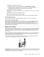
Display

: Position the display to maintain a comfortable viewing distance of 510 mm to 760 mm (20 inches to 

30 inches). Avoid glare or reflections on the display from overhead lighting or outside sources of light. Keep 
the display screen clean and set the brightness to levels that enable you to see the screen clearly. Press the 
brightness control keys to adjust display brightness.

Head position

: Keep your head and neck in a comfortable and neutral (vertical, or upright) position.

Chair

: Use a chair that gives you good back support and seat height adjustment. Use chair adjustments to 

best suit your comfort posture.

Arm and hand position

: If available, use chair arm rests or an area on your working surface to provide 

weight support for your arms. Keep your forearms, wrists, and hands in a relaxed and neutral (horizontal) 
position. Type with a soft touch without pounding the keys.

Leg position

: Keep your thighs parallel to the floor and your feet flat on the floor or on a footrest.

62

User Guide

Summary of Contents for 90RE

Page 1: ...User Guide IdeaCentre Gaming 5i 14L 6 IdeaCentre Creator 5i 14L 6 and IdeaCentre Gaming 5 14L 6 ...

Page 2: ... Warranty Guide Generic Safety and Compliance Notices Setup Guide First Edition March 2021 Copyright Lenovo 2021 LIMITED AND RESTRICTED RIGHTS NOTICE If data or software is delivered pursuant to a General Services Administration GSA contract use reproduction or disclosure is subject to restrictions set forth in Contract No GS 35F 05925 ...

Page 3: ...ore system files and settings to an earlier point 19 Restore your files from a backup 19 Reset your computer 20 Use advanced options 20 Windows automatic recovery 20 Create and use a recovery USB device 20 Update the device driver 21 Chapter 5 CRU replacement 23 CRU list 23 Remove or replace a CRU 24 Power cord 24 Computer cover 25 Front bezel 27 2 5 inch storage drive for selected models 30 Stora...

Page 4: ...ii User Guide ...

Page 5: ...computer including this User Guide To get the latest documentation go to https pcsupport lenovo com Microsoft makes periodic feature changes to the Windows operating system through Windows Update As a result some information in this documentation might become outdated Refer to Microsoft resources for the latest information This guide applies to the Lenovo product models listed below Illustrations ...

Page 6: ...iv User Guide ...

Page 7: ... 1 5 USB 3 2 connector Gen 2 6 SD card slot for selected models Power indicator Show the system status of your computer On The computer is on Off The computer is off or in hibernation mode Blinking The computer is in sleep mode Related topics USB specifications on page 3 Use a media card on page 10 Copyright Lenovo 2021 1 ...

Page 8: ...SB 2 0 connectors 4 5 Ethernet connector 6 Wireless antennas 7 PCI Express card area 8 Power cord connector 9 Padlock loop 10 Security lock slot for IdeaCentre Gaming5 14ACN6 only Related topics USB specifications on page 3 Connect to the wired Ethernet on page 5 Lock the computer on page 6 2 User Guide ...

Page 9: ...then click System Memory Double data rate 4 DDR4 dual in line memory module DIMM Storage device To view the storage drive capacity of your computer right click the Start button to open the Start context menu and then click Disk Management Note The storage drive capacity indicated by the system is less than the nominal capacity Expansion SD card slot DDR4 DIMM slots M 2 solid state drive slot 2280 ...

Page 10: ...ixels 60 Hz Connect to USB C accessories to help expand your computer functionality To purchase USB C accessories go to https www lenovo com accessories Statement on USB transfer rate Depending on many factors such as the processing capability of the host and peripheral devices file attributes and other factors related to system configuration and operating environments the actual transfer rate usi...

Page 11: ...ct your computer to a local network through the Ethernet connector on your computer with an Ethernet cable Connect to Wi Fi networks Click the network icon in the Windows notification area and then select a network for connection Provide required information if needed Manage cables with a smart cable clip Note You can purchase a smart cable clip from Lenovo Copyright Lenovo 2021 5 ...

Page 12: ...esponsible for evaluating selecting and implementing the locking device and security feature Lenovo makes no comments judgments or warranties about the function quality or performance of the locking device and security feature You can purchase computer locks from Lenovo Padlock Locking the computer cover through a padlock prevents unauthorized access to the inside of your computer 6 User Guide ...

Page 13: ...Kensington style cable lock Lock your computer to a desk table or other fixtures through a Kensington style cable lock Chapter 2 Get started with your computer 7 ...

Page 14: ...8 User Guide ...

Page 15: ...computer hardware and diagnose hardware problems Look up warranty status online Access User Guide and helpful articles Notes The available features vary depending on the computer model Lenovo Vantage makes periodic updates of the features to keep improving your experience with your computer The description of features might be different from that on your actual user interface Set the power plan Fo...

Page 16: ...ollow the on screen instructions Use a media card If your computer has a SD card slot read the following information Install a media card 1 Locate the SD card slot 2 Ensure that the metal contacts on the card are facing the ones in the SD card slot Insert the card firmly into the SD card slot until it is secured in place Remove a media card Attention Before removing a media card eject the card fro...

Page 17: ...sories and upgrades to help expand the capabilities of your computer Options include memory modules storage devices network cards power adapters keyboards mice and more To shop at Lenovo go to https www lenovo com accessories Chapter 3 Explore your computer 11 ...

Page 18: ...12 User Guide ...

Page 19: ...c All connected devices that require ac power are connected to properly grounded and working electrical outlets d All connected devices are enabled in UEFI BIOS 2 Use an antivirus program if any to see if the computer has been infected by a virus If the program detects a virus remove the virus 3 See Chapter 4 Troubleshooting diagnostics and recovery on page 13 to resolve the problem you are experi...

Page 20: ...tart up from the correct storage drive or fails to start up Ensure that all storage drive signal cables and power cables are connected correctly Ensure that the storage drive the computer starts up from is listed as the first startup device in UEFI BIOS In rare cases the storage drive with the operating system might get corrupted or damaged In such cases you might need to replace the storage drive...

Page 21: ...ts the audio function built into the system board is disabled Therefore you must use the audio connectors on the audio adapter Ensure that the program you are running is designed for use in the Microsoft Windows operating system If the program is designed to run in DOS the program does not use the Windows sound feature The program must be configured to use SoundBlaster Pro or SoundBlaster emulatio...

Page 22: ... a wrong duplex mode might degrade performance cause data loss or result in lost connections When a Gigabit Ethernet model computer is used at a speed of 1000 Mbps the Ethernet LAN connection fails or errors occur Connect the network cable to the Ethernet connector using Category 5 wiring and a 100 BASE T hub switch not 100 BASE X The Wake On LAN WOL feature does not work Enable the Wake On LAN fe...

Page 23: ... then click Enable device 4 Expand Network adapters to display all network devices Right click each Bluetooth device and then click Enable device Turn on the Bluetooth radio 1 Open the Start menu 2 Click Settings Devices Bluetooth other devices 3 Turn on the Bluetooth switch to enable the Bluetooth feature Update or reinstall the Bluetooth driver Sound does not come from the Bluetooth headset or h...

Page 24: ...ive 1 Open the Start menu 2 Click Windows System File Explorer This PC 3 Right click your C drive and then click Properties 4 Check the amount of free space and then click Disk Cleanup 5 A list of unnecessary file categories is displayed Select the category you want to delete and then click OK Disable some Windows features or remove some unnecessary programs 1 Go to Control Panel and view by large...

Page 25: ... the problem is caused by a program Refer to the printed documentation that comes with the program or the help system of the program Update the program Uninstall the program and then reinstall it To download a program that is preinstalled on your computer go to https pcsupport lenovo com and follow the on screen instructions Recovery This section introduces the recovery information of the Windows ...

Page 26: ...instructions Create and use a recovery USB device It is recommended that you create a recovery USB drive as early as possible as a backup for the Windows recovery programs With the recovery USB drive you can troubleshoot and fix the problems even if the preinstalled Windows recovery programs are damaged Create a recovery USB drive Attention The creation process deletes anything stored on the USB d...

Page 27: ...mponent or when you added a component This action might eliminate the driver as the potential cause of a problem Download and install the latest driver by one of the following methods From Lenovo Vantage Open Lenovo Vantage to check the available update packages If the latest UEFI BIOS update package is available follow the on screen instructions to download and install the package From the Lenovo...

Page 28: ...22 User Guide ...

Page 29: ...om Lenovo at any time upon request You might be required to return the defective part that is replaced by the CRU When return is required 1 return instructions a prepaid shipping label and a container will be included with the replacement CRU and 2 you might be charged for the replacement CRU if Lenovo does not receive the defective CRU within thirty 30 days of your receipt of the replacement CRU ...

Page 30: ...d print the following instructions Before you remove the power cord turn off the computer and wait several minutes until the computer is cool Replacement procedure 1 Turn off the computer and remove all connected devices 2 Disconnect the power cord from the electrical outlet 3 Disconnect the power cord from the computer 4 Connect the new power cord to the computer 24 User Guide ...

Page 31: ...ollowing instructions Before you open the computer cover turn off the computer and wait several minutes until the computer is cool Replacement procedure 1 Remove the power cord See Power cord on page 24 2 Unlock any locking device that secures the computer cover See Lock the computer on page 6 3 Remove the screws and then remove the computer cover by sliding it out Chapter 5 CRU replacement 25 ...

Page 32: ...26 User Guide ...

Page 33: ...ailable use it to lock the computer cover Front bezel Prerequisites Before you start read Generic Safety and Compliance Notices and print the following instructions Before you open the computer cover turn off the computer and wait several minutes until the computer is cool Replacement procedure 1 Remove the power cord See Power cord on page 24 Chapter 5 CRU replacement 27 ...

Page 34: ...2 Remove the computer cover See Computer cover on page 25 3 Remove the front bezel by releasing the three plastic tabs as shown 28 User Guide ...

Page 35: ...4 Remove the front bezel 5 Align the new front bezel with the holes on the front of the chassis Chapter 5 CRU replacement 29 ...

Page 36: ...g guidelines Replace the internal storage drive only for upgrade or repair The internal storage drive is not designed for frequent changes or replacement Before replacing the internal storage drive make a backup copy of all the data that you want to keep Do not touch the contact edge of the internal storage drive Otherwise the internal storage drive might get damaged Do not apply pressure to the i...

Page 37: ...le from the storage drive 4 Remove the screws securing the storage drive to the storage drive bay assembly 5 Remove the storage drive from the storage drive bay 6 Install the new storage drive into the storage drive bay 7 Screw the storage drive back into the storage drive bay Chapter 5 CRU replacement 31 ...

Page 38: ...structions Replacement procedure 1 Remove the power cord See Power cord on page 24 2 Remove the computer cover See Computer cover on page 25 3 Remove the front bezel See Front bezel on page 27 4 Disconnect the signal cable and the power cable from the storage drive Notes The storage drive will vary depending on your model If your model has a 3 5 inch storage drive follow step 1 on the illustration...

Page 39: ...5 Release the latch on the storage drive bay and pull slightly Chapter 5 CRU replacement 33 ...

Page 40: ...6 Slide the storage drive bay towards the front of the case and rotate it away from the case 34 User Guide ...

Page 41: ...ve Notes The storage drive will vary depending on your model If your model has a 3 5 inch storage drive see 3 5 inch storage drive on page 38 If your model has a 2 5 inch storage drive see 2 5 inch storage drive for selected models on page 30 Chapter 5 CRU replacement 35 ...

Page 42: ...9 Mount the new storage drive bay on the case 36 User Guide ...

Page 43: ...10 Close the storage drive bay and slide it back into place 11 Push the storage drive bay into the case to engage the latch Chapter 5 CRU replacement 37 ...

Page 44: ...pliance Notices and print the following instructions Attention The internal storage drive is sensitive Inappropriate handling might cause damage and permanent loss of data When handling the internal storage drive observe the following guidelines Replace the internal storage drive only for upgrade or repair The internal storage drive is not designed for frequent changes or replacement Before replac...

Page 45: ... cover See Computer cover on page 25 3 Remove the storage drive bay See Storage drive bay 4 Remove the screws securing the storage drive to the storage drive bay 5 Slide the storage drive out of the storage drive bay 6 Install the new storage drive in the storage drive bay 7 Screw the storage drive back into the storage drive bay 8 Reinstall all removed parts Then reconnect the power cord and all ...

Page 46: ...mputer cover on page 25 3 Remove the storage drive bay See Storage drive bay 4 If available in your model remove the 3 5 inch storage drive See 3 5 inch storage drive on page 38 5 Slide each storage drive rubber and pull away from storage drive bay 6 Insert each new storage drive rubber and secure into storage drive bay 7 Reinstall all removed parts Then reconnect the power cord and all disconnect...

Page 47: ...ing the internal storage drive make a backup copy of all the data that you want to keep Do not touch the contact edge of the internal storage drive Otherwise the internal storage drive might get damaged Replacement procedure 1 Remove the power cord See Power cord on page 24 2 Remove the computer cover See Computer cover on page 25 3 Remove the storage drive bay See Storage drive bay 4 Remove the M...

Page 48: ... computer Memory modules Prerequisite Before you start read Generic Safety and Compliance Notices and print the following instructions Replacement procedure 1 Remove the power cord See Power cord on page 24 2 Remove the computer cover See Computer cover on page 25 3 Remove the storage drive bay See Storage drive bay 42 User Guide ...

Page 49: ...4 Disengage the tabs on the memory modules 5 Remove the memory module Chapter 5 CRU replacement 43 ...

Page 50: ... the tabs 8 Reinstall all removed parts Then reconnect the power cord and all disconnected cables to the computer Microprocessor heatsink and fan assembly Before you start read Generic Safety and Compliance Notices and print the following instructions 44 User Guide ...

Page 51: ...er cover on page 25 3 Remove the storage drive bay See Storage drive bay 4 Remove the fan power cable from the system board 5 Remove the heatsink mounting screws Note Carefully remove the screws from the system board to avoid any possible damage to the system board The screws cannot be removed from the heatsink 6 Remove the heatsink and fan Notes Do not touch the thermal paste while handling the h...

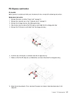
Page 52: ...e following instructions The PCI Express card might be very hot Before you open the computer cover turn off the computer and wait several minutes until the computer is cool Replacement procedure 1 Remove the power cord See Power cord on page 24 2 Remove the computer cover See Computer cover on page 25 3 Remove the storage drive bay See Storage drive bay 4 Open the latch 5 Press the tab until you h...

Page 53: ...ot 7 Remove the screws holding the PCI Express card and the PCI Express card bracket together 8 Pull the PCI Express card bracket away from the PCI Express card 9 Install the new PCI Express card into the PCI Express card bracket Chapter 5 CRU replacement 47 ...

Page 54: ...ard bracket 11 Install the PCI Express card into the PCI Express slot pressing down until you hear a pop from the tab 12 Close the latch 13 Reinstall all removed parts Then reconnect the power cord and all disconnected cables to the computer 48 User Guide ...

Page 55: ...age drive bay See Storage drive bay 4 Press the two tabs to release the PCI Express card holder from the storage drive bay 5 Remove the PCI Express card holder from the storage drive bay 6 Install the new PCI Express card holder onto the storage drive bay 7 Make sure that the PCI Express card holder tabs are fully latched into the storage drive bay 8 Reinstall all removed parts Then reconnect the ...

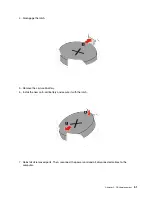
Page 56: ... vent from the battery or coin cell battery Note To dispose of the coin cell battery refer to Lithium coin cell battery notice in the Safety and Warranty Guide Your computer has a special type of memory that maintains the date time and settings for built in features such as parallel connector assignments configurations A coin cell battery keeps this information active when you turn off the compute...

Page 57: ...Remove the coin cell battery 6 Install the new coin cell battery and secure it with the latch 7 Reinstall all removed parts Then reconnect the power cord and all disconnected cables to the computer Chapter 5 CRU replacement 51 ...

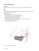
Page 58: ...r is cool Replacement procedure 1 Remove the power cord See Power cord on page 24 2 Remove the computer cover See Computer cover on page 25 3 Remove the storage drive bay See Storage drive bay 4 Disconnect the power cable from the system board 5 Remove the power supply assembly mounting screws from the rear of the computer case 6 Press the power supply assembly tab to release 7 Remove the power su...

Page 59: ...wer supply assembly mounting screws 10 Connect the power cable into the system board 11 Reinstall all removed parts Then reconnect the power cord and all disconnected cables to the computer Chapter 5 CRU replacement 53 ...

Page 60: ...54 User Guide ...

Page 61: ...t documentation Safety and Warranty Guide Generic Safety and Compliance Notices Setup Guide This User Guide Regulatory Notice Go to https pcsupport lenovo com Then follow the on screen instructions to filter out the documentation you want Lenovo Support Web site with the latest support information of the following Drivers and software Diagnostic solutions Product and service warranty Product and p...

Page 62: ... Which version Which software applications were running at the time of the problem Can the problem be reproduced If so how 2 Record the system information Product name Machine type and serial number The following illustration shows where to find the machine type and serial number of your computer Lenovo Customer Support Center During the warranty period you can call Lenovo Customer Support Center ...

Page 63: ...authorized by Lenovo will make selected Engineering Changes ECs that apply to your hardware available Services not covered Replacement or use of parts not manufactured for or by Lenovo or nonwarranted parts Identification of software problem sources Configuration of UEFI BIOS as part of an installation or upgrade Changes modifications or upgrades to device drivers Installation and maintenance of n...

Page 64: ...58 User Guide ...

Page 65: ...k Turn on or turn off Mouse Keys Left Alt Left Shift PrtScn or PrtSc Turn on or turn off High Contrast For more information go to https windows microsoft com and then search using any of the following keywords keyboard shortcuts key combinations shortcut keys Ease of Access Center Ease of Access Center on the Windows operating system enables you to configure your computers to suit their physical a...

Page 66: ...rite and send e mails To use Speech Recognition 1 Go to Control Panel and view by Category 2 Click Ease of Access Speech Recognition 3 Follow the on screen instructions Screen reader technologies Screen reader technologies are primarily focused on software program interfaces help systems and various online documents For additional information about screen readers see the following Use PDFs with sc...

Page 67: ...ough a screen reader Each image in the documentation also includes adequate alternative text so that visually impaired users can understand the image when they use a screen reader Ergonomic information Good ergonomic practice is important to get the most from your personal computer and to avoid discomfort Arrange your workplace and the equipment you use to suit your individual needs and the kind o...

Page 68: ... Keep your head and neck in a comfortable and neutral vertical or upright position Chair Use a chair that gives you good back support and seat height adjustment Use chair adjustments to best suit your comfort posture Arm and hand position If available use chair arm rests or an area on your working surface to provide weight support for your arms Keep your forearms wrists and hands in a relaxed and ...

Page 69: ...rmful interference to radio or television reception which can be determined by turning the equipment off and on the user is encouraged to try to correct the interference by one or more of the following measures Reorient or relocate the receiving antenna Increase the separation between the equipment and receiver Connect the equipment into an outlet on a circuit different from that to which the rece...

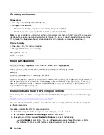
Page 70: ...을 충족합니다 본 장치는 무선 송수신기 입니다 본 장치는 국제 가이드라인으로 권장되는 전파 노출에 대한 제한을 초과하지 않도록 설계되었습니다 장치 액세서리 및 최신 부품을 사용할 경우 SAR 값이 달라질 수 있 습니다 SAR 값은 국가 보고 및 테스트 요구 사항과 네트워크 대역에 따라 다를 수 있습니다 본 장치 는 사람의 신체에서 20mm 이상의 거리에서 사용할 수 있습니다 Enable or disable the ErP LPS compliance mode Lenovo computers meet the eco design requirements of the ErP Lot 3 regulation For more information go to https www lenovo com us en compliance ...

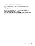
Page 71: ... Wake Up on Alarm feature to make the computer wake up at a set time To meet the off mode requirement of ErP compliance you need to disable the Fast Startup function 1 Go to Control Panel and view by large icons or small icons 2 Click Power Options Choose what the power buttons do Change settings that are currently unavailable 3 Clear the Turn on fast startup recommended option from the Shutdown s...

Page 72: ...66 User Guide ...

Page 73: ...ht to improve and or modify the products and software programs described in the manuals included with your computer and the content of the manual at any time without additional notice The software interface and function and hardware configuration described in the manuals included with your computer might not match exactly the actual configuration of the computer that you purchase For the configura...

Page 74: ... software included with this product Lenovo may update this document at any time without notice For the latest information or any questions or comments contact or visit the Lenovo Web site https pcsupport lenovo com Trademarks LENOVO LENOVO logo and IDEACENTRE are trademarks of Lenovo Intel Optane and Thunderbolt are trademarks of Intel Corporation or its subsidiaries in the U S and or other count...

Page 75: ......

Page 76: ......
Reviews: