background image

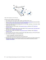
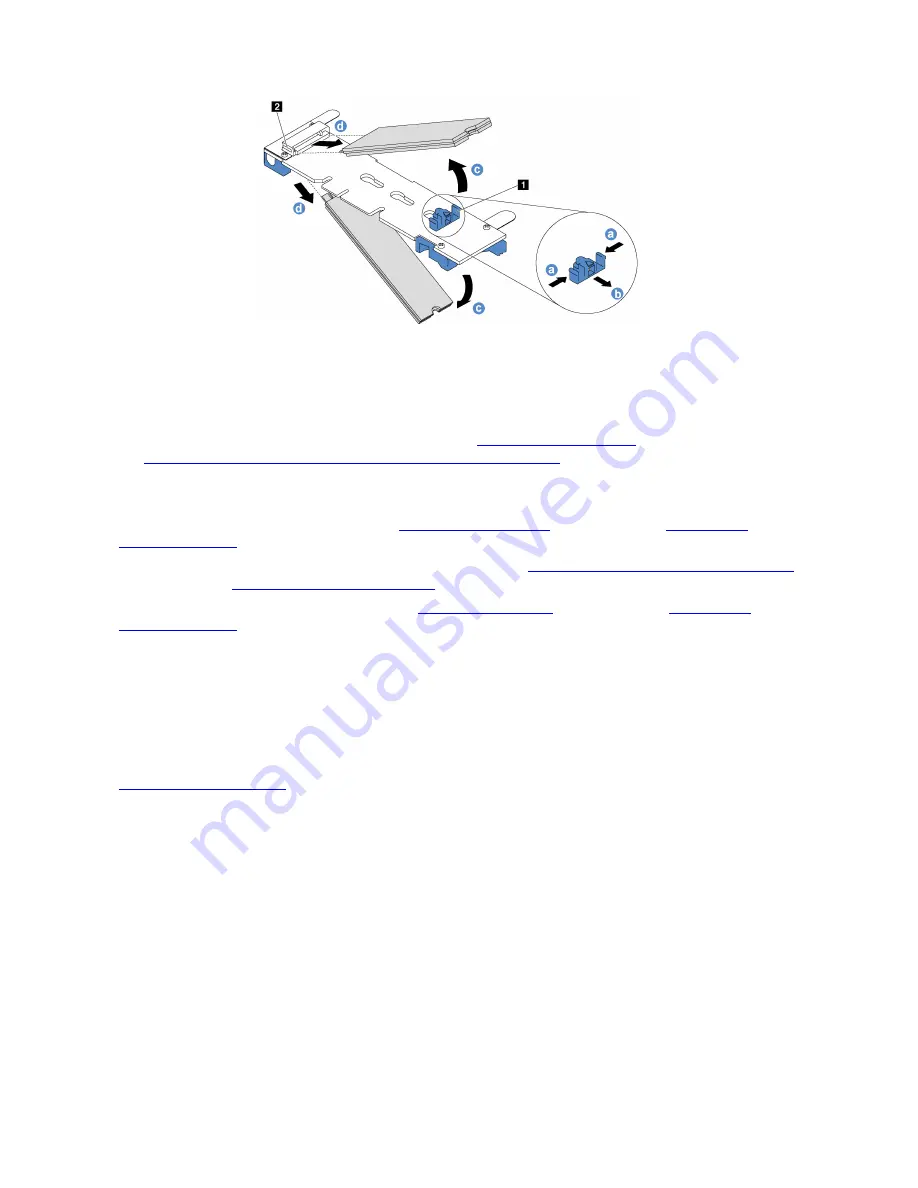
Figure 12. M.2 backplane and two M.2 drives

To replace the M.2 backplane and M.2 drive: 

1.  From vSphere web client migrate all VMs if DRS is not enabled on the cluster.

2.  Place the node in maintenance mode by following the 

Enter Maintenance Mode

procedure described in 

the 

VMware Storage and Availability Technical Documents Repository

.

3.  Power off the node and if the cable management arm is not in place, disconnect all the cables. Pull the 

node chassis out of the rack.

4.  Remove the top cover as described in the 

Removing the top cover

procedure in the 

ThinkSystem 

Information Center

.

5.  Replace the M.2 backplane and M.2 drive as described in the 

M.2 backplane and M.2 drive replacement

procedure in the 

ThinkSystem Information Center

.

6.  Close the memory DIMM as described in the 

Closing the top cover

procedure in the 

ThinkSystem 

Information Center

.

7.  Push the node chassis back into the rack and reconnect the cables as necessary. Power on the node.

8.  Verify that the M.2 adapter is successfully replaced: 

•  Amber warning light on the node front panel is off

•  System boots successfully with no POST errors or other errors

9.  Bring replaced component to the Best Recipe code levels that correspond to the other components in 

the solution. All components in the solution must be contained within one Best Recipe listed in 

ThinkAgile VX Best Recipe

14

Lenovo ThinkAgile Hardware Replacement Guide for VX1320 Appliance, VX 1SE Certified Node

Summary of Contents for 7Z58CTO1WW

Page 1: ...Lenovo ThinkAgile Hardware Replacement Guide for VX1320 Appliance VX 1SE Certified Node Machine Types 7Z58 ...

Page 2: ...ddition be sure that you are familiar with the terms and conditions of the Lenovo warranty for your server which can be found at https datacentersupport lenovo com us zh warrantylookup Second Edition December 2019 Copyright Lenovo 2019 LIMITED AND RESTRICTED RIGHTS NOTICE If data or software is delivered pursuant to a General Services Administration GSA contract use reproduction or disclosure is s...

Page 3: ...y unit PSU 8 Replace a chassis fan 9 Replace a network interface card NIC 10 Replace a host bus adapter HBA 11 Replace a memory DIMM 13 Replace an M 2 Adapter 13 Chapter 4 Software tools 15 Advanced Settings Utility 15 VMware Support Link 15 Chapter 5 Configuration procedures 17 UEFI boot mode 17 Bios Optimization 18 Appendix A Notices 23 Appendix B Trademarks 25 Index 27 Copyright Lenovo 2019 i ...

Page 4: ...ii Lenovo ThinkAgile Hardware Replacement Guide for VX1320 Appliance VX 1SE Certified Node ...

Page 5: ...ement Node power on unless it is a hot swap part Verify the problem is resolved by part replacement Return failed part s to Lenovo Customer replaceable units CRUs are parts that can be replaced in the ThinkAgile VX1320 Appliance VX 1SE Certified Node models Note parts cannot be removed or added Replacement of CRUs is user responsibility Lenovo charges for CRU installation at user request The most ...

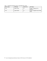
Page 6: ...CTO numbers Machine Type CTO Model Form Factor CTO Name 7Z58 7Z58CTO1WW 1U Lenovo ThinkAgile VX1320 Appliance 7Z58 7Z58CTO2WW 1U Lenovo ThinkAgile VX 1SE Certified Node 2 Lenovo ThinkAgile Hardware Replacement Guide for VX1320 Appliance VX 1SE Certified Node ...

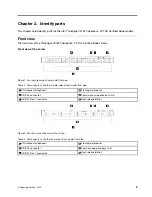
Page 7: ...ble 2 Components on the four simple swap drives model front view 1 VGA connector optional 4 Front operator panel 2 USB 2 0 connector 5 Four simple swap drive bays 0 3 3 USB 3 1 Gen 1 connector 6 Rack release latches Figure 2 Four hot swap drives model front view Table 3 Components on the four hot swap drives model front view 1 VGA connector optional 4 Front operator panel 2 USB 2 0 connector 5 Fou...

Page 8: ...ase latches Figure 4 Ten 2 5 inch hot swap drives model front view Note The last two drive bays may not be supported if only the eight bay backplane is installed Table 5 Components on the ten 2 5 inch hot swap drives model front view 1 USB 2 0 connector 4 VGA connector optional 2 USB 3 1 Gen 1 connector 5 Ten 2 5 inch hot swap drive bays 0 9 3 Front operator panel 6 Rack release latches 4 Lenovo T...

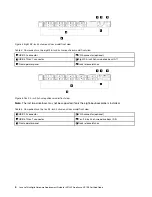
Page 9: ...e 6 Rear view Non redundant power supply model 1 PCIe slot 1 6 Ethernet connector 1 shared with XCC network port 2 PCIe slot 2 7 Dedicated XCC network connector 3 Power connector 8 VGA connector 4 USB 3 1 Gen 2 connectors 9 Serial connector 5 Ethernet connector 2 Figure 7 Rear view Redundant power supply model Chapter 2 Identify parts 5 ...

Page 10: ...rnet connector has two status LEDs to help you identify the Ethernet connectivity and activity If the LOM adapter is not installed Ethernet connector 1 can be set as XCC Network connector To set Ethernet connector 1 as XCC Network connector start Setup Utility and select BMC Settings Network Settings Network Settings Network Interface Port Shared Then click Shared NIC on and select Onboard Port 1 ...

Page 11: ...tified Node model contains solid state drives SSDs and hard disk drives HDDs User data is striped across these drives so they are referred to as data drives A node might be able to self correct for a data drive failure but does lead to system degradation Replace failed data drives quickly A failed data drive is indicated by The vSphere Web console displays a disk error The amber LED on the front o...

Page 12: ...Sphere client Hardware Status tab shows a power supply alert Table 8 Power supply options Feature Display Description Maximum quantity Part number B40Q ThinkSystem SR250 SR150 Fixed 300W Power Supply 1 None B40R ThinkSystem 450W 230V 115V Platinum Hot Swap Power Supply 2 4P57A12649 B5LC ThinkSystem 450W 230V 115V Platinum Hot Swap Power Supply India 2 4P57A16264 Figure 8 Hot swap power supply To r...

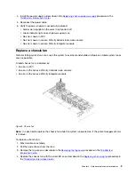
Page 13: ...tdown Replace a failed system fan as soon as possible A failed chassis fan is indicated by An error in XCC An error in the Lenovo XClarity Controller web console An error in the Lenovo XClarity Integrator console Figure 9 Chassis fan Note It is possible to replace the chassis fan while the system is powered on if the cable management arm is in place To replace a chassis fan 1 Enter maintenance mod...

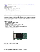
Page 14: ...ad port 10GBE 25GBE port and two 1GBE ports onboard connected to the motherboard A node requires network connectivity to function as part of a cluster If one network interface is available the failure of the other network interfaces does not cause service interruption A failed NIC is indicated by No LED is illuminated for the network interface Guest VM performance degrades Guest VMs the vSphere we...

Page 15: ...ocedure in the ThinkSystem Information Center 7 Push the node chassis back into the rack and reconnect the cables as necessary Power on the node 8 Bring replaced component to the Best Recipe code levels that correspond to the other components in the solution All components in the solution must be contained within one Best Recipe listed in ThinkAgile VX Best Recipe 9 Exit maintenance mode 10 Verify...

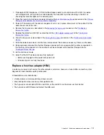
Page 16: ... the ThinkSystem Information Center 5 Close the top cover as described in the Closing the top cover procedure in the ThinkSystem Information Center 6 Push the node chassis back into the rack and reconnect the cables as necessary Power on the node 7 Verify that the HBA is successfully replaced Amber warning light on the server is off All of the drives are shown as online Verify the LSI HBA card is ...

Page 17: ...lity Technical Documents Repository 3 Power off the node and if the cable management arm is not in place disconnect all the cables Pull the node chassis out of the rack 4 Remove the top cover as described in the Removing the top cover procedure in the ThinkSystem Information Center 5 Remove the air baffle as described in Removing the air baffle procedure in the ThinkSystem Information Center 6 Rep...

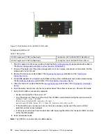
Page 18: ... M 2 drive as described in the M 2 backplane and M 2 drive replacement procedure in the ThinkSystem Information Center 6 Close the memory DIMM as described in the Closing the top cover procedure in the ThinkSystem Information Center 7 Push the node chassis back into the rack and reconnect the cables as necessary Power on the node 8 Verify that the M 2 adapter is successfully replaced Amber warning...

Page 19: ...odify selected settings in the integrated management module Modify a limited number of VPD settings Remote connectivity to support setting all the listed firmware types settings Remote connection support requires accessing the XCC external port over a LAN For more information and to download the ASU program go to the Advanced Settings Utility ASU for Lenovo x86 servers website VMware Support Link ...

Page 20: ...16 Lenovo ThinkAgile Hardware Replacement Guide for VX1320 Appliance VX 1SE Certified Node ...

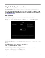
Page 21: ... to enable UEFI boot mode if not already enabled asu64 set BootModes SystemBootMode UEFI Mode Figure 11 shows where to change the setting from the UEFI setup page accessed via F1 during boot Figure 13 UEFI Boot Mode Select UEFI Boot Mode to ensure that HARD DISK 0 in the boot order uses the M 2 SSD for the hypervisor boot drive Use the ASU system tool or other means to select UEFI Boot Mode asu64 ...

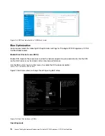
Page 22: ...cessors to allow the network adapters to place data directly into the CPU cache which reduces cache misses and can improve performance Use the ASU system tool or other means to enable the DCA processor option asu64 set Processors DCA Enable Figure 13 illustrates where to change the setting using UEFI setup Figure 15 Direct Cache Access DCA Operating mode 18 Lenovo ThinkAgile Hardware Replacement G...

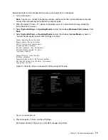
Page 23: ...d set the mode as Custom Mode as shown in Custom Mode figure then set UEFI settings as follows Choose Operating Mode Custom Memory Speed Max Performance CPU P state Control Autonomous C1 Enhance Mode Disable UPI Link Frequency Max Performance UPI Link Disable Enable All Links Turbo Mode Enable Energy Efficient Turbo Enable C States Disable Power Performance Bias Platform Controlled Platform Contro...

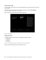
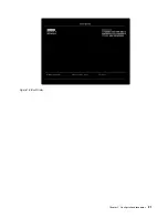
Page 24: ...ontrolled Figure 15 illustrates where to change the setting using UEFI setup Figure 17 OS Controlled Configure Boot Order Use the ASU system tool or other means to configure the boot order as follows 1 CD DVD Rom 2 Hard Disk 0 3 PXE Network asu64 set BootOrder BootOrder UEFI Only CD DVD Rom Hard Disk 0 PXE Network Figure 16 illustrates the final boot order in the UEFI setup screen 20 Lenovo ThinkA...

Page 25: ...Figure 18 Boot Order Chapter 5 Configuration procedures 21 ...

Page 26: ...22 Lenovo ThinkAgile Hardware Replacement Guide for VX1320 Appliance VX 1SE Certified Node ...

Page 27: ...n new editions of the publication Lenovo may make improvements and or changes in the product s and or the program s described in this publication at any time without notice The products described in this document are not intended for use in implantation or other life support applications where malfunction may result in injury or death to persons The information contained in this document does not ...

Page 28: ...24 Lenovo ThinkAgile Hardware Replacement Guide for VX1320 Appliance VX 1SE Certified Node ...

Page 29: ...Appendix B Trademarks LENOVO LENOVO logo and THINKSYSTEM are trademarks of Lenovo All other trademarks are the property of their respective owners 2019 Lenovo Copyright Lenovo 2019 25 ...

Page 30: ...26 Lenovo ThinkAgile Hardware Replacement Guide for VX1320 Appliance VX 1SE Certified Node ...

Page 31: ...lane and M 2 drive replacing 13 N notices 23 P PCIe adapter replacing 10 pull out information tab 3 R rack latch 3 RAID adapter replacing 11 rear view 5 replacing DIMM 13 hard disk drive 7 hot swap drive 7 hot swap power supply 8 M 2 backplane and M 2 drive 13 PCIe adapter 10 RAID adapter 11 solid state drive 7 system fan 9 S solid state drive replacing 7 system fan replacing 9 T trademarks 25 V V...

Page 32: ...28 Lenovo ThinkAgile Hardware Replacement Guide for VX1320 Appliance VX 1SE Certified Node ...

Page 33: ......

Page 34: ......

Reviews: