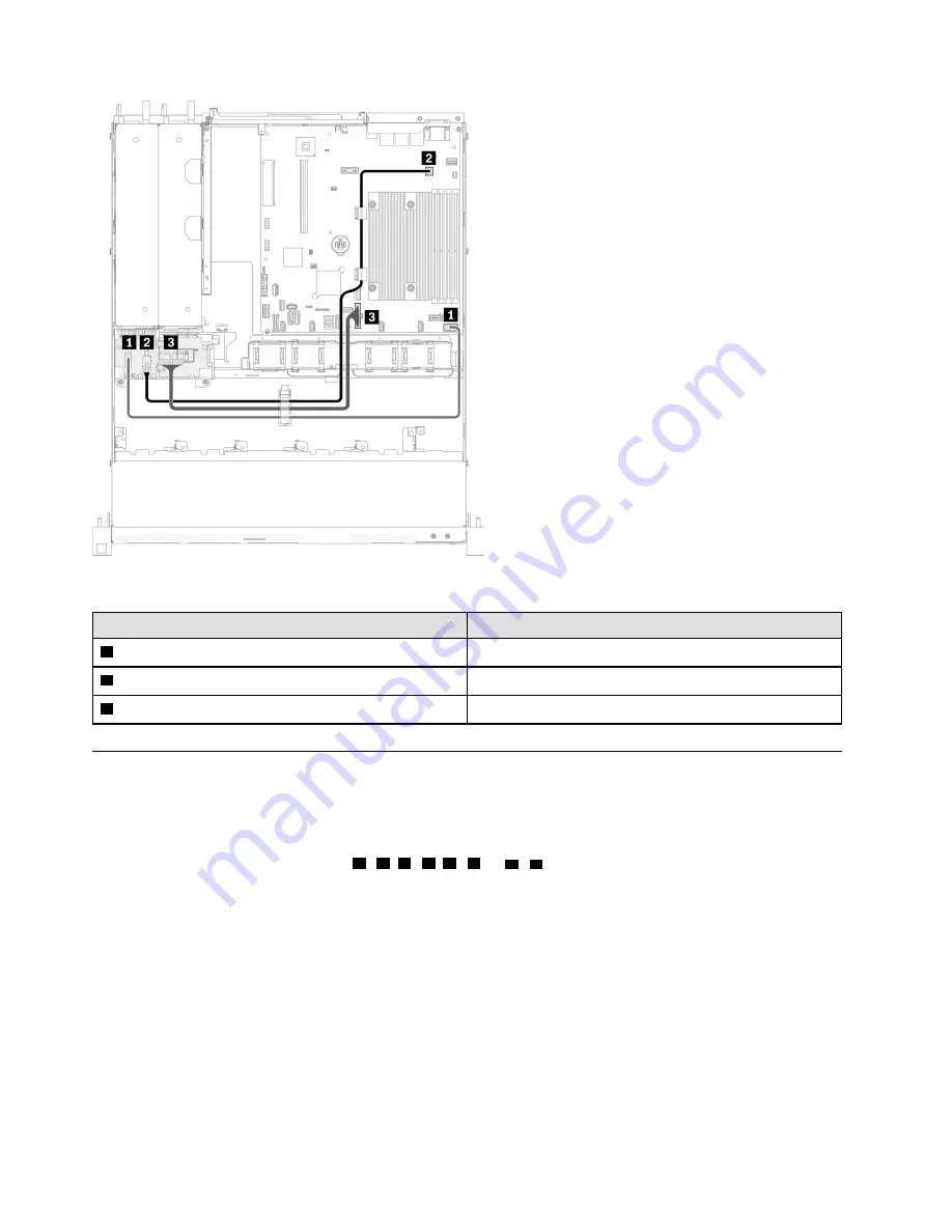
Figure 32. Hot-swap power supply unit cable routing
From
To
1
PDB: Power distribution board signal connector
System board: Power distribution board signal connector
2
PDB: Processor power connector
System board: Processor power connector
3
PDB: System power connector
System board: System power connector
Flash power module cable routing
Use the section to understand the internal routing and connectors for the flash power module.
Notes:
• Connections between connectors;
1
↔
1
,
2
↔
2
,
3
↔
3
, ...
n
↔
n
• When routing the cables, ensure that all cables are routed appropriately through the cable guides and
cable clips.
40
ThinkSystem SR250 V2 Maintenance Manual
Summary of Contents for 7D7Q
Page 1: ...ThinkSystem SR250 V2 Maintenance Manual Machine Types 7D7Q and 7D7R ...
Page 8: ...vi ThinkSystem SR250 V2 Maintenance Manual ...
Page 20: ...12 ThinkSystem SR250 V2 Maintenance Manual ...
Page 42: ...34 ThinkSystem SR250 V2 Maintenance Manual ...
Page 176: ...168 ThinkSystem SR250 V2 Maintenance Manual ...
Page 180: ...172 ThinkSystem SR250 V2 Maintenance Manual ...
Page 183: ......
Page 184: ......


