


Chapter 9. Removing and replacing a FRU
This chapter presents directions and drawings for use in removing and replacing a FRU. Be sure to observe
the following general rules:
1. Do not try to service any computer unless you have been trained and certified. An untrained person runs
the risk of damaging parts.
2. Before replacing any FRU, review Chapter 8 “FRU replacement notices” on page 63.
3. Begin by removing any FRUs that have to be removed before the failing FRU. Any such FRUs are listed
at the top of the page. Remove them in the order in which they are listed.
4. Follow the correct sequence in the steps for removing the FRU, as given in the drawings by the
numbers in square callouts.
5. When turning a screw to replace a FRU, turn it in the direction as given by the arrow in the drawing.
6. When removing the FRU, move it in the direction as given by the arrow in the drawing.
7. To put the new FRU in place, reverse the removal procedure and follow any notes that pertain to
replacement. For information about connecting and arranging internal cables, see Chapter 10
“Locations” on page 153.
8. When replacing a FRU, use the correct screw as shown in the procedures.
DANGER
Before removing any FRU, turn off the computer, unplug all power cords from electrical outlets,
remove the battery pack, and then disconnect any interconnecting cables.
Attention:
After replacing a FRU, do not turn on the computer until you have made sure that all screws,
springs, and other small parts are in place and none are loose inside the computer. Verify this by shaking
the computer gently and listening for rattling sounds. Metallic parts or metal flakes can cause electrical
short circuits.
Attention:
The system board is sensitive to, and can be damaged by, electrostatic discharge. Before
touching it, establish personal grounding by touching a ground point with one hand or by using an
electrostatic discharge (ESD) strap (P/N 6405959).
Important notice for servicing ThinkPad W700ds and W701ds
The computer display is designed to be opened and used at an angle slightly greater than 90 degrees. Do
not open the main display beyond 150 degrees. To do so might damage the computer hinge.
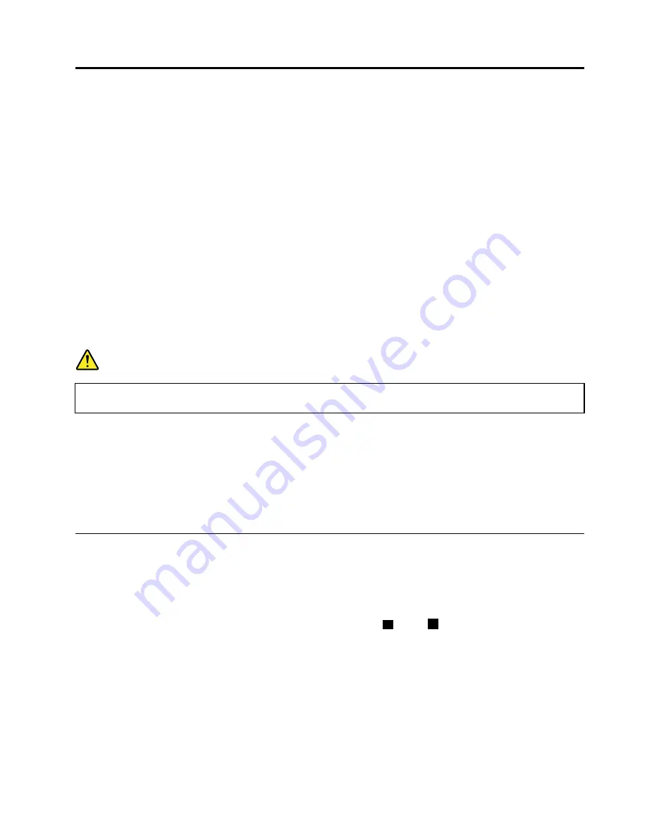
Tips on using the dual screen model:
• The second screen is designed to be opened at an angle of 0 (
a
) to 30 (
b
) degrees to the main display.
Do not open it to an angle of more than 30 degrees. To do so might damage it.
© Copyright Lenovo 2008, 2011
67
Summary of Contents for 27523KU
Page 1: ...ThinkPad W700 W700ds W701 and W701ds Hardware Maintenance Manual ...
Page 6: ...iv ThinkPad W700 W700ds W701 and W701ds Hardware Maintenance Manual ...
Page 11: ...DANGER DANGER DANGER DANGER DANGER DANGER Chapter 1 Safety information 5 ...
Page 12: ...DANGER 6 ThinkPad W700 W700ds W701 and W701ds Hardware Maintenance Manual ...
Page 13: ...PERIGO PERIGO PERIGO Chapter 1 Safety information 7 ...
Page 15: ...DANGER DANGER DANGER DANGER DANGER Chapter 1 Safety information 9 ...
Page 17: ...VORSICHT VORSICHT VORSICHT VORSICHT VORSICHT VORSICHT Chapter 1 Safety information 11 ...
Page 18: ...12 ThinkPad W700 W700ds W701 and W701ds Hardware Maintenance Manual ...
Page 19: ...Chapter 1 Safety information 13 ...
Page 20: ...14 ThinkPad W700 W700ds W701 and W701ds Hardware Maintenance Manual ...
Page 21: ...Chapter 1 Safety information 15 ...
Page 22: ...16 ThinkPad W700 W700ds W701 and W701ds Hardware Maintenance Manual ...
Page 25: ...Chapter 1 Safety information 19 ...
Page 26: ...20 ThinkPad W700 W700ds W701 and W701ds Hardware Maintenance Manual ...
Page 27: ...Chapter 1 Safety information 21 ...
Page 28: ...22 ThinkPad W700 W700ds W701 and W701ds Hardware Maintenance Manual ...
Page 29: ...Chapter 1 Safety information 23 ...
Page 30: ...24 ThinkPad W700 W700ds W701 and W701ds Hardware Maintenance Manual ...
Page 34: ...28 ThinkPad W700 W700ds W701 and W701ds Hardware Maintenance Manual ...
Page 44: ...38 ThinkPad W700 W700ds W701 and W701ds Hardware Maintenance Manual ...
Page 64: ...58 ThinkPad W700 W700ds W701 and W701ds Hardware Maintenance Manual ...
Page 68: ...62 ThinkPad W700 W700ds W701 and W701ds Hardware Maintenance Manual ...
Page 72: ...66 ThinkPad W700 W700ds W701 and W701ds Hardware Maintenance Manual ...
Page 158: ...152 ThinkPad W700 W700ds W701 and W701ds Hardware Maintenance Manual ...
Page 164: ...1 2 3b 3a 4 5 6 7 8 9 10 158 ThinkPad W700 W700ds W701 and W701ds Hardware Maintenance Manual ...
Page 196: ...3 4 5 6 9 10 4 1 8 7 2 190 ThinkPad W700 W700ds W701 and W701ds Hardware Maintenance Manual ...
Page 199: ...LCD FRUs for ThinkPad W701ds 3 4 9 8 6 2 1 14 12 13 11 10 15 5 7 Chapter 11 Parts list 193 ...
Page 214: ...208 ThinkPad W700 W700ds W701 and W701ds Hardware Maintenance Manual ...
Page 217: ......
Page 218: ...Part Number 43Y9442_07 1P P N 43Y9442_07 43Y9442_07 ...