Lenovo 019727U Hardware Maintenance Manual Download Page 135

2020 LCD latch L and R

For access, remove the following FRU:

v

“1010 Battery pack” on page 83

v

“2010 LCD bezel assembly” on page 125

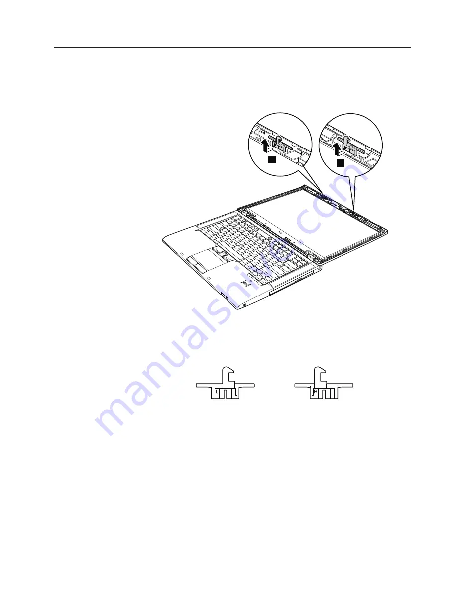
Table 29. Removal steps of LCD latch L and R

1

1

When installing:

Attach the LCD latch marked

L

to the left-hand side and the

LCD latch marked

R

to the right-hand side.

Removing and replacing a FRU

127

Summary of Contents for 019727U

Page 1: ...ThinkPad T400s Hardware Maintenance Manual ...

Page 2: ......

Page 3: ...ThinkPad T400s Hardware Maintenance Manual ...

Page 4: ...exclusively at private expense and are sold to governmental entities as commercial items as defined by 48 C F R 2 101 with limited and restricted rights to use reproduction and disclosure LIMITED AND RESTRICTED RIGHTS NOTICE If products data computer software or services are delivered pursuant a General Services Administration GSA contract use reproduction or disclosure is subject to restrictions ...

Page 5: ...eric error codes 61 Error messages 65 Beep symptoms 66 No beep symptoms 66 LCD related symptoms 67 Intermittent problems 68 Undetermined problems 68 Specifications 69 Status indicators 71 Fn key combinations 75 FRU replacement notices 77 Screw notices 77 Retaining serial numbers 78 Restoring the serial number of the system unit 78 Retaining the UUID 78 Reading or writing the ECA information 79 Rem...

Page 6: ... Starter Edition 32 bit recovery DVDs 164 Windows Vista Home Basic 32 bit recovery DVDs 165 Windows Vista Home Premium 32 bit recovery DVDs 166 Windows Vista Business 32 bit recovery DVDs 167 Windows Vista Business 64 bit recovery DVDs 169 Windows Vista Ultimate 32 bit recovery DVDs 170 Common service tools 171 Notices 173 Trademarks 174 iv ThinkPad T400s Hardware Maintenance Manual ...

Page 7: ...agnostic tests to troubleshoot problems Important This manual is intended only for trained servicers who are familiar with ThinkPad products Use this manual along with the advanced diagnostic tests to troubleshoot problems effectively Before servicing a ThinkPad product be sure to read all the information under Safety information on page 1 and Important service information on page 39 Copyright Len...

Page 8: ...vi ThinkPad T400s Hardware Maintenance Manual ...

Page 9: ...v General safety on page 2 v Electrical safety on page 3 v Safety inspection guide on page 5 v Handling devices that are sensitive to electrostatic discharge on page 6 v Grounding requirements on page 6 v Safety notices multilingual translations on page 7 v Laser compliance statement multilingual translations on page 28 Copyright Lenovo 2009 1 ...

Page 10: ...he machine v Keep your toolcase away from walk areas so that other people will not trip over it v Do not wear loose clothing that can be trapped in the moving parts of a machine Make sure that your sleeves are fastened or rolled up above your elbows If your hair is long fasten it v Insert the ends of your necktie or scarf inside clothing or fasten it with a nonconductive clip about 8 centimeters 3...

Page 11: ...bserving the above rule you may prevent a current from passing through your body When using testers set the controls correctly and use the approved probe leads and accessories for that tester Stand on suitable rubber mats obtained locally if necessary to insulate you from grounds such as metal floor strips and machine frames Observe the special safety precautions when you work with very high volta...

Page 12: ...arts with the power on when they are removed from their normal operating places in a machine Power supply units Pumps Blowers and fans Motor generators Similar units to listed above This practice ensures correct grounding of the units v If an electrical accident occurs Use caution do not become a victim yourself Switch off power Send another person to get medical aid 4 ThinkPad T400s Hardware Main...

Page 13: ... determine whether there are any potentially unsafe conditions use the following checklist at the beginning of every service task Begin the checks with the power off and the power cord disconnected Checklist 1 Check exterior covers for damage loose broken or sharp edges 2 Power off the computer Disconnect the power cord 3 Check the power cord for a A third wire ground connector in good condition U...

Page 14: ... surface The mat is especially useful when handling ESD sensitive devices v Select a grounding system such as those listed below to provide protection that meets the specific service requirement Attach the ESD ground clip to any frame ground ground braid or green wire ground When working on a double insulated or battery operated system use an ESD common ground or reference point You can use coax o...

Page 15: ...translations The safety notices in this section are provided in the following languages v English v Arabic v Brazilian Portuguese v French v German v Hebrew v Japanese v Korean v Spanish v Traditional Chinese Safety information 7 ...

Page 16: ...or water or short circuit it Dispose of the battery pack as required by local ordinances or regulations Use only the battery in the appropriate parts listing when replacing the battery pack Use of an incorrect battery can result in ignition or explosion of the battery DANGER The lithium battery can cause a fire an explosion or a severe burn Do not recharge it remove its polarized connector disasse...

Page 17: ...ge a shorted or grounded battery can produce enough current to burn personnel or combustible materials DANGER Unless hot swap is allowed for the FRU being replaced do as follows before removing it power off the computer unplug all power cords from electrical outlets remove the battery pack and disconnect any interconnecting cables Safety information 9 ...

Page 18: ...10 ThinkPad T400s Hardware Maintenance Manual ...

Page 19: ...Safety information 11 ...

Page 20: ...u na água ou deixe o entrar em curto circuito Descarte o pacote da bateria conforme requerido pelas leis ou regulamentos locais Use somente a bateria nas partes listadas apropriadas ao substituir o pacote da bateria O uso de uma bateria incorreta pode resultar em combustão ou explosão da bateria PERIGO A bateria de lítio pode causar incêndio explosão ou graves queimaduras Não a recarregue remova s...

Page 21: ...o circuito ou aterrada pode produzir corrente o bastante para queimar materiais de pessoal ou inflamáveis PERIGO A menos que uma hot swap seja permitida para a FRU que está sendo substituída faça o seguinte antes de removê la desligue o computador desconecte todos os cabos de energia das tomadas remova o pacote de baterias e desconecte quaisquer cabos de interconexão Safety information 13 ...

Page 22: ...démontez pas ne l exposez ni au feu ni à l eau Ne la mettez pas en court circuit Pour la mettre au rebut conformez vous à la réglementation en vigueur Lorsque vous remplacez la batterie veillez à n utiliser que les modèles cités dans la liste de pièces détachées adéquate En effet une batterie inappropriée risque de prendre feu ou d exploser DANGER La pile de sauvegarde contient du lithium Elle pré...

Page 23: ...ie peut produire suffisamment de courant pour brûler des matériaux combustibles ou causer des brûlures corporelles graves DANGER Si le remplacement à chaud n est pas autorisé pour l unité remplaçable sur site que vous remplacez procédez comme suit avant de retirer l unité mettez l ordinateur hors tension débranchez tous les cordons d alimentation des prises de courant retirez le bloc de batterie e...

Page 24: ...tz falscher Batterien kann zu Entzündung oder Explosion führen VORSICHT Akkus enthalten geringe Mengen von Nickel Sie dürfen nicht zerlegt wiederaufgeladen kurzgeschlossen oder Feuer oder Wasser ausgesetzt werden Bei der Entsorgung die örtlichen Bestimmungen für Sondermüll beachten Beim Ersetzen der Batterie nur Batterien des Typs verwenden der in der Ersatzteilliste aufgeführt ist Der Einsatz fal...

Page 25: ...schließend ein Arzt aufgesucht werden VORSICHT Aus Sicherheitsgründen die Kunststoffabdeckung die den unteren Teil der Spannungswandlerplatine umgibt nicht entfernen VORSICHT Obwohl Hauptbatterien eine niedrige Spannung haben können sie doch bei Kurzschluß oder Erdung genug Strom abgeben um brennbare Materialien zu entzünden oder Verletzungen bei Personen hervorzurufen VORSICHT Wenn ein Austausch ...

Page 26: ...18 ThinkPad T400s Hardware Maintenance Manual ...

Page 27: ...Safety information 19 ...

Page 28: ...20 ThinkPad T400s Hardware Maintenance Manual ...

Page 29: ...Safety information 21 ...

Page 30: ...22 ThinkPad T400s Hardware Maintenance Manual ...

Page 31: ...Safety information 23 ...

Page 32: ...antidades de níquel No las desmonte ni recargue ni las eche al fuego o al agua ni las cortocircuite Deséchelas tal como dispone la normativa local Utilice sólo baterías que se encuentren en la lista de piezas al sustituir la batería La utilización de una batería no apropiada puede provocar la ignición o explosión de la misma PELIGRO La batería de repuesto es una batería de litio y puede provocar i...

Page 33: ...ede producir la corriente suficiente como para quemar material combustible o provocar quemaduras en el personal PELIGRO Salvo que se permita el intercambio en caliente para la unidad sustituible localmente realice lo siguiente antes de extraerla apague el sistema desconecte todos los cables de alimentación de las tomas de alimentación eléctrica extraiga la batería y desconecte los cables de interc...

Page 34: ...26 ThinkPad T400s Hardware Maintenance Manual ...

Page 35: ...Safety information 27 ...

Page 36: ...e requirements of the International Electrotechnical Commission IEC 60825 1 and CENELEC EN 60825 1 for Class 1 laser products If a CD ROM drive a DVD ROM drive or another laser device is installed note the following CAUTION Use of controls or adjustments or performance of procedures other than those specified herein might result in hazardous radiation exposure Opening the CD ROM drive the DVD ROM ...

Page 37: ...Safety information 29 ...

Page 38: ...unidade de DVD ROM ou outro dispositivo de laser estiver instalado observe o seguinte CUIDADO O uso de controles ou ajustes ou a execução de procedimentos diferentes dos especificados nesta documentação pode resultar em exposição perigosa à radiação Abrir a unidade de CD ROM a unidade de DVD ROM ou qualquer outro dispositivo de armazenamento ótico pode resultar em exposição perigosa à radiação de ...

Page 39: ...informations suivantes ATTENTION Pour éviter tout risque d exposition au rayon laser respectez les consignes de réglage et d utilisation des commandes ainsi que les procédures décrites dans le présent manuel L ouverture de l unité de CD ROM de l unité de DVD ROM ou de toute autre unité de stockage optique peut entraîner une exposition à des radiations dangereuses Aucune pièce de ces unités n est r...

Page 40: ...se oder die Nichteinhaltung der hier beschriebenen Einstellungen oder Bedienschritte kann zur Freisetzung gefährlicher Laserstrahlung führen Beim Öffnen eines CD ROM Laufwerks DVD ROM Laufwerks oder anderen optischen Speicherlaufwerks können gefährliche Laserstrahlungen freigesetzt werden Die Laufwerke enthalten keine zu wartenden Teile Laufwerke nicht öffnen Ein installiertes CD ROM Laufwerk DVD ...

Page 41: ...Safety information 33 ...

Page 42: ...34 ThinkPad T400s Hardware Maintenance Manual ...

Page 43: ...Safety information 35 ...

Page 44: ... ROM DVD ROM u otro dispositivo láser tenga en cuenta lo siguiente PRECAUCIÓN La utilización de controles ajustes o la realización de procedimientos diferentes a los especificados puede dar como resultado una exposición peligrosa a radiaciones Si abre la unidad de CD ROM DVD ROM o cualquier otro dispositivo de almacenamiento óptico podría quedar expuesto a una radiación láser peligrosa No hay piez...

Page 45: ...Safety information 37 ...

Page 46: ...38 ThinkPad T400s Hardware Maintenance Manual ...

Page 47: ...d service technicians are available in the following support site http www lenovoservicetraining com ion Advise customers to contact the Customer Support Center at 800 426 7378 if they need assistance in obtaining or installing any software fixes drivers and BIOS downloads Customers in Canada should call the Customer Support Center at 800 565 3344 for assistance or download information Before repl...

Page 48: ...at before replacing a hard disk drive This will cause all customer data on the hard disk to be lost Be sure that the customer has a current backup of the data before doing this task Attention The drive startup sequence in the computer you are servicing may have been changed Be extremely careful during write operations such as copying saving or formatting If you select an incorrect drive data or pr...

Page 49: ...e 1829 CTO Again CMVs are custom models and are not found in the HMM General Announce Variant GAV This is a standard model fixed configuration GAVs are announced and offered to all customers The MTM portion of the machine label is a 4 digit MT and 3 digit model where model a fixed part number not CTO Example 1829 F1U Also PEW eSupport and the HMM will list these products under the same fixed model...

Page 50: ... Type in the model type and serial number The key commodities will be returned in the eSupport record under PARTS SHIPPED WITH YOUR SYSTEM For the Remaining FRUs the complete list of FRUs at the MT Model level v eSupport can be used to view the complete list of FRUs for a machine type and model v To view the complete list of FRUs type in the machine type and model Example 1829 CTO under QUICK PATH...

Page 51: ... new nylon coated screws v Be extremely careful during such write operations as copying saving or formatting Drives in the computer that you are servicing sequence might have been altered If you select an incorrect drive data or programs might be overwritten v Replace a FRU only with another FRU of the correct model When you replace a FRU make sure that the model of the machine and the FRU part nu...

Page 52: ...referring to the following list The following are not covered under warranty v LCD panel cracked from the application of excessive force or from being dropped v Scratched cosmetic parts v Distortion deformation or discoloration of the cosmetic parts v Plastic parts latches pins or connectors that have been cracked or broken by excessive force v Damage caused by liquid spilled into the system v Dam...

Page 53: ... as follows 1 Turn on the computer 2 When the ThinkPad logo comes up immediately press F1 to enter the BIOS Setup Utility Note If a supervisor password has been set by the customer BIOS Setup Utility menu appears after the password is entered You can start the utility by pressing Enter instead of entering the supervisor password however you cannot change the parameters that are protected by the su...

Page 54: ...ct ATAPI CDx x 0 1 and then press Enter 7 Follow the instructions on the screen 8 The main panel of PC Doctor appears 9 Select Diagnostics with the arrow keys and press Enter Note You can select an item not only with the arrow keys but also with the TrackPoint pointer Instead of pressing Enter click the left button A pull down menu appears Its exact form depends on the model Note PC Doctor menu do...

Page 55: ... your computer detach it before running PC Doctor for DOS v To test Digital Signature Chip the security chip must be set to Active 10 Run the applicable function test 11 Follow the instructions on the screen If there is a problem PC Doctor shows messages describing it 12 To exit the test select Quit Exit Diag To cancel the test press Esc Note After running PC Doctor check the time and date on the ...

Page 56: ...Rescue and Recovery In some models of ThinkPad Notebook the Rescue and Recovery workspace enables you to run the PC Doctor program to test the hardware features of the computer To run the test click Run Diagnostics on the Rescue and Recovery main screen FRU tests The following table shows the test for each FRU Table 1 FRU tests FRU Applicable test System board 1 Diagnostics CPU Coprocessor 2 Diagn...

Page 57: ...BIOS Setup Utility 4 Using cursor keys select HDD diagnostic program Press enter 5 Using cursor keys select Main hard disk drive or Ultrabay hard disk drive 6 Press Enter to start the diagnostic program Diskette drive 1 Diagnostics Diskette Drives 2 Interactive Tests Diskette Optical drive 1 Diagnostics Other Devices Optical Drive 2 Interactive Tests Optical Drive Test Memory 1 If two DIMMs are in...

Page 58: ...t work check the configuration as specified in the BIOS Setup Utility If the Touch Pad is disabled select Automatic to enable it If enabling the Touch Pad does not correct the problem continue with the following v Interactive Tests Mouse 50 ThinkPad T400s Hardware Maintenance Manual ...

Page 59: ...ccurs only when the docking station or the port replicator is used replace the docking station or the port replicator v If the power on indicator does not turn on check the power cord of the AC adapter for correct continuity and installation v If the computer does not charge during operation go to Checking operational charging on page 52 To check the AC adapter do the following 1 Unplug the AC ada...

Page 60: ...ger Gauge icon in the icon tray of the Windows taskbar and wait for a moment but do not click and the percentage of battery power remaining is displayed To get detailed information about the battery double click the Power Manager Gauge icon Note If the battery pack becomes hot it may not be able to charge Remove it from the computer and leave it at room temperature for a while After it cools down ...

Page 61: ...ove the backup battery see 1080 Backup battery on page 100 5 Measure the voltage of the backup battery See the following figure Red Black Wire Voltage V dc Red 2 5 to 3 2 Black Ground v If the voltage is correct replace the system board v If the voltage is not correct replace the backup battery v If the backup battery discharges quickly after replacement replace the system board General checkout 5...

Page 62: ...54 ThinkPad T400s Hardware Maintenance Manual ...

Page 63: ...ystem Recovery Disc when prompted and click Yes to begin the operating system recovery process 5 Insert the Product Recovery Disc when prompted and click OK 6 If you have a Supplemental Recovery Disc insert it when prompted and click Yes If you do not have a Supplemental Recovery Disc click No Note Not all recovery disc sets come with a Supplemental Recovery Disc If there is a Supplemental Recover...

Page 64: ...to the hard disk even if the user has changed the user HDP Note There are two modes for the HDP User only and Master User The Master User mode requires two HDPs the system administrator enters both in the same operation The system administrator then provides the user HDP to the system user Attention If the user HDP has been forgotten check whether a master HDP has been set If it has it can be used...

Page 65: ...assphrase item is displayed in the menu this function is available on the ThinkPad Notebook 3 Select Security using the cursor directional keys to move down the menu 4 Select Password 5 Select Power On Password 6 Type the current SVP in the Enter Current Password field then leave the Enter New Password field blank and press Enter twice 7 In the Changes have been saved window press Enter 8 Press F1...

Page 66: ...g the cursor directional keys to move down the menu 4 Select Password 5 Select Hard disk x password where x is the letter of the hard disk drive A pop up window opens 6 Select Master HDP 7 Type the current master HDP in the Enter Current Password field then leave the Enter New Password field blank and press Enter twice 8 Press F10 9 Select Yes in the Setup Configuration window Both user HDP and ma...

Page 67: ...e has been set on the timer and the user does not do any operation with the keyboard the TrackPoint the hard disk the parallel connector or the diskette drive within that time v If the battery indicator blinks orange indicating that the battery power is low Note Even if you do not set the low battery alarm the charge indicator notifies you when the battery is low and then the computer enters the p...

Page 68: ...ng Fn F4 keys Also the computer goes into hibernation mode automatically in either of the following conditions v If a hibernation time has been set on the timer and if the user does not do any operation with the keyboard the TrackPoint the hard disk drive the parallel connector or the diskette drive within that time v If the timer conditions are satisfied in suspend mode When the power is turned o...

Page 69: ...eck the narrative descriptions of symptoms If the symptom is not described there go to Intermittent problems on page 68 Numeric error codes Table 2 Numeric error codes Symptom or error FRU or action in sequence 0175 Bad CRC1 stop POST task The EEPROM checksum is not correct System board 0176 System Security The system has been tampered with 1 Run BIOS Setup Utility and save the current setting by ...

Page 70: ...evice that you installed or press Esc to ignore the warning message 2 System board 01CA More than one Wireless LAN devices are found Remove one of them 1 Remove the wireless LAN device that you installed 2 System board 0200 Hard disk error The hard disk is not working 1 Reseat the hard disk drive 2 Load Setup Defaults in BIOS Setup Utility 3 Hard disk drive 4 System board 021x Keyboard error Run i...

Page 71: ...board 0271 Date and time error Neither the date nor the time is set in the computer Run BIOS Setup Utility to reset the time and date 0280 Previous boot incomplete Default configuration used 1 Load Setup Default in BIOS Setup Utility 2 DIMM 3 System board 02F0 CPU ID xx Failed 1 CPU 2 System board 02F4 EISA CMOS not writable 1 Load Setup Defaults in BIOS Setup Utility 2 Replace the backup battery ...

Page 72: ...ion Test 2010 Warning Your internal hard disk drive HDD may not function correctly on this system Ensure that your HDD is supported on this system and that the latest HDD firmware is installed Inform the following information to the customer If in the primary bay the customer is using a non IBM or non Lenovo hard disk drive HDD or an old generation IBM HDD which is not supported by this system wit...

Page 73: ... 1 Restore the system configuration to what it was before the computer entered hibernation mode 2 If memory size has been changed re create the hibernation file Fan error 1 Fan 2 Thermal grease 3 System board Thermal sensing error System board Cannot boot from any device Check the status of device which you want to boot from Device not found 1 The device you want to boot from 2 System board Device...

Page 74: ...eps and one short beep Only the cursor appears Reinstall the operating system Four cycles of four short beeps and a blank screen System board security chip Five short beeps and a blank screen System board No beep symptoms Table 5 No beep symptoms Symptom or error FRU or action in sequence No beep power on indicator on LCD blank and no POST 1 Make sure that every connector is connected tightly and ...

Page 75: ...he TFT LCD for the notebook computer contains many thin film transistors TFTs The presence of a small number of dots that are missing discolored or always lighted is characteristic of TFT LCD technology but excessive pixel problems can cause viewing concerns If the LCD you are servicing has two or less visible defective pixels it should not be considered faulty However if the LCD has three or more...

Page 76: ...do not isolate FRUs that have no defects Verify that all attached devices are supported by the computer Verify that the power supply being used at the time of the failure is operating correctly See Power system checkout on page 51 1 Turn off the computer 2 Visually check each FRU for damage Replace any damaged FRU 3 Remove or disconnect all of the following devices a Non ThinkPad devices b Devices...

Page 77: ...1 GB DDR3 1066 SDRAM SO DIMM PC3 8500 card v 2 GB DDR3 1066 SDRAM SO DIMM PC3 8500 card v 4 GB DDR3 1066 SDRAM SO DIMM PC3 8500 card maximum of 8 0 GB Note Due to the limitation of the current 32 bit PC architecture actual usable memory size is limited to 2 5 GB even though the physical memory size is 8 GB Extended memory device some models v Intel Turbo Memory 2 GB half size v Intel Turbo Memory ...

Page 78: ...apter III v Qualcomm UNDP1 Wireless WAN card v Ericsson F3507g USA Wireless WAN card v Ericsson F3507g Other Wireless WAN card v Wireless USB PCI Express Half Mini Card Media slot v 34 mm ExpressCard slot or 5 in 1 Media Card Reader slot Bluetooth wireless v ThinkPad Bluetooth with Enhanced Data Rate BDC 2 1 Touch pad v UltraNav ThinkLight Yes Battery v Li ion battery 6 cells AC adapter v 65 watt ...

Page 79: ...Status indicators The system status indicators show the status of the computer as follows 3 4 5 6 8 9 7 2 1 11 10 Copyright Lenovo 2009 71 ...

Page 80: ...tandby mode or turn off the computer Note Do not move the system while the green device access light is on Sudden physical shock could cause drive errors 6 Power on Green The computer is on and ready to use This indicator stays lit around the power on button whenever the computer is on and is not in standby mode 7 Ultrabay Slim Media Bay device status Green An Ultrabay Slim Media Bay device is ins...

Page 81: ...e capacity Blinking green slow The battery is charged between 20 to 80 of the capacity and being charged Orange The battery is charged between 5 and 20 of the capacity and being discharged Blinking orange slow The battery is charged between 5 to 20 of the capacity and being charged Blinking orange rapid The battery is charged between 0 to 5 of the capacity Status indicators 73 ...

Page 82: ...74 ThinkPad T400s Hardware Maintenance Manual ...

Page 83: ...nction key Notes 1 To use the Fn F4 key combination you must have the ThinkPad PM device driver installed on the computer 2 This combination of keys also functions as a sleep button If you want to use the combination to put the computer into hibernation mode or shut the computer down change the settings in the Power Manager Fn F5 Enable or disable the built in wireless networking features and the ...

Page 84: ... F9 Reserved Fn F10 Reserved Fn F11 Reserved Fn F12 Put the computer into hibernation mode To return to normal operation press the power button for less than four seconds Note To use Fn F12 for hibernation you must have the ThinkPad PM device driver installed on the computer Fn PgUp Turn the ThinkLight on or off Note This function is supported only on the ThinkPad Notebooks that have the ThinkLigh...

Page 85: ... bag v Always use new screws v Use a torque screwdriver if you have one Tighten screws as follows v Plastic to plastic Turn an additional 90 degrees after the screw head touches the surface of the plastic part 90 degrees more Cross section v Logic card to plastic Turn an additional 180 degrees after the screw head touches the surface of the logic card 180 degrees more Cross section v Torque driver...

Page 86: ... computer is displayed the serial number of the system unit is listed as follows v 20 Serial number Write down that number Note The serial number of the system unit is also written on the label attached to the bottom of the computer After you have replaced the system board restore the serial number by doing the following 1 Install the LENOVO ThinkPad Hardware Maintenance Diskette Version 1 76 or l...

Page 87: ...Version 1 76 or later and restart the computer 2 From the main menu select 6 Set ECA Information 3 To read ECA information select 2 Read ECA rework number from EEPROM and follow the instruction 4 To read box build date select 5 Read box build date from EEPROM and follow the instruction on the screen After an ECA has been applied to the machine the EEPROM must be updated to reflect the ECA s applic...

Page 88: ...80 ThinkPad T400s Hardware Maintenance Manual ...

Page 89: ... drawing 7 To put the new FRU in place reverse the removal procedure and follow any notes that pertain to replacement For information about connecting and arranging internal cables see Locations on page 141 8 When replacing a FRU use the correct screw as shown in the procedures DANGER Before removing any FRU turn off the computer unplug all power cords from electrical outlets remove the battery pa...

Page 90: ...move the SIM card you need to remove the battery pack first See 1010 Battery pack on page 83 After you finish the servicing make sure that you insert the card back into the slot firmly Notice on disconnecting the cable from flip lock ZIF connector Some cables used in the ThinkPad T400s are connected to the flip lock ZIF connectors When disconnecting the cable from those connectors do as shown in t...

Page 91: ... 10 Removal steps of battery pack Unlock the battery latch 1 Holding the battery latch in the unlocked position 2 remove the battery pack in the direction shown by arrow 3 and 4 3 3 4 1 2 When installing Install the battery pack in the slot and then make sure that the battery latch is in the locked position Removing and replacing a FRU 83 ...

Page 92: ...ble 11 Removal steps of Ultrabay Slim Media Bay device or travel bezel Holding the bay lock latch in the unlocked position 1 slide the bay eject latch 2 and then pull out the Ultrabay Slim Media Bay device or the travel bezel in the direction shown by arrow 3 3 2 1 4 84 ThinkPad T400s Hardware Maintenance Manual ...

Page 93: ...on coated 1 Black 0 167 Nm 1 7 kgfcm Attention v Do not drop the drive or apply any physical shock to it The drive is sensitive to physical shock Improper handling can cause damage and permanent loss of data v Before removing the drive have the user make a backup copy of all the information on it if possible v Never remove the drive while the system is operating or is in suspend mode Removing and ...

Page 94: ...Table 12 Removal steps of SSD or HDD continued 3 4 When installing Make sure that the SSD connector or HDD connector is attached firmly 86 ThinkPad T400s Hardware Maintenance Manual ...

Page 95: ...1040 DIMM For access remove these FRUs in order v 1010 Battery pack on page 83 Table 13 Removal steps of DIMM Note Loosen the screws 1 but do not remove them 1 2 Removing and replacing a FRU 87 ...

Page 96: ...ard must be installed in SLOT 0 a but not in SLOT 1 b 3 3 4 a b When installing Insert the notched end of the DIMM into the socket Press the DIMM firmly and pivot it until it snaps into the place Make sure that it is firmly fixed in the slot and does not move easily 88 ThinkPad T400s Hardware Maintenance Manual ...

Page 97: ... wireless LAN For access remove these FRUs in order v 1010 Battery pack on page 83 Table 14 Removal steps of PCI Express Mini Card for wireless LAN Note Loosen the screws 1 but do not remove them 1 2 Removing and replacing a FRU 89 ...

Page 98: ...ntenna RF connector P N 08K7159 or pick the connectors with your fingers and gently unplug them in direction of the arrow Note Some models might have only two antenna cables in step 3 3 4 4 Step Screw quantity Color Torque 4 M2 3 mm small head nylon coated 2 Silver 0 167 Nm 1 7 kgfcm 90 ThinkPad T400s Hardware Maintenance Manual ...

Page 99: ... the black cable into the jack labeled AUX or A on the card If the computer you are servicing has three cables put the white cable in the cable protection tube v In models with wireless LAN card that has three antenna connectors plug the gray cable MAIN into the jack labeled TR1 the white cable 3rd into jack labeled RO or TR3 and the black cable AUX into jack labeled TR2 on the card Removing and r...

Page 100: ...ss WAN For access remove these FRUs in order v 1010 Battery pack on page 83 Table 15 Removal steps of PCI Express Mini Card for wireless WAN Note Loosen the screws 1 but do not remove them 1 2 92 ThinkPad T400s Hardware Maintenance Manual ...

Page 101: ... the jacks by using the removal tool antenna RF connector P N 08K7159 or pick the connectors with your fingers and gently unplug them in direction of the arrow 3 4 4 Step Screw quantity Color Torque 4 M2 3 mm small head nylon coated 2 Silver 0 167 Nm 1 7 kgfcm Removing and replacing a FRU 93 ...

Page 102: ... steps of PCI Express Mini Card for wireless WAN continued 5 Note Plug the orange cable into the jack labeled MAIN and the blue cable into the jack labeled AUX on the card 94 ThinkPad T400s Hardware Maintenance Manual ...

Page 103: ...1070 Keyboard For access remove these FRUs in order v 1010 Battery pack on page 83 Table 16 Removal steps of keyboard Note Loosen the screws 1 but do not remove them 1 2 Removing and replacing a FRU 95 ...

Page 104: ... Step Screw quantity Color Torque 3 M2 6 mm bind head nylon coated 2 Black 0 167 Nm 1 7 kgfcm Push down the keyboard a little toward the arrow 4 and then lift up the keyboard in the direction of 5 4 5 5 5 96 ThinkPad T400s Hardware Maintenance Manual ...

Page 105: ...Table 16 Removal steps of keyboard continued Lift the keyboard a little in the direction shown by arrow 6 and then detach the connector 7 6 7 Removing and replacing a FRU 97 ...

Page 106: ...When installing the keyboard do as follows Table 17 Installation steps of keyboard 1 Attach the keyboard connector 98 ThinkPad T400s Hardware Maintenance Manual ...

Page 107: ...nder the frame as shown in this figure a a a 3 To make sure that the front side of the keyboard is housed firmly gently press the keys with your thumbs and try to slide the keyboard toward you 4 Secure the keyboard by tightening the screws from the bottom side of the computer Removing and replacing a FRU 99 ...

Page 108: ...ecified in the parts list for your computer Any other battery could ignite or explode Table 18 Removal steps of backup battery 1 2 When installing Attach the backup battery on the hole a in the insulation sheet as shown in the figure below and make sure that the battery connector is attached firmly a 100 ThinkPad T400s Hardware Maintenance Manual ...

Page 109: ... Turbo Memory Minicard skip step 1 In step 1 unplug the jack by using the removal tool antenna RF connector P N 08K7159 or pick the connector with your fingers and gently unplug them in direction of the arrow 2 2 1 When installing In models with the wireless USB adapter route the antenna cable as shown in this figure and plug the cable firmly into the jack on the adapter Step Screw quantity Color ...

Page 110: ...Table 19 Removal steps of wireless USB adapter or Intel Turbo Memory continued 3 102 ThinkPad T400s Hardware Maintenance Manual ...

Page 111: ...nt reader 2 2 1 1 1 1 1 1 1 1 Step Screw quantity Color Torque 1 M2 4 mm bind head nylon coated 8 Black 0 167 Nm 1 7 kgfcm 2 M2 6 mm bind head nylon coated 2 Black 0 167 Nm 1 7 kgfcm Note In models with the fingerprint reader the sensor is attached to the palm rest FRU If the fingerprint reader has any defects you can replace it by the procedures given in this section which are the same for a palm...

Page 112: ...Table 20 Removal steps of palm rest or palm rest with fingerprint reader continued 3 4 6 5 6 6 5 104 ThinkPad T400s Hardware Maintenance Manual ...

Page 113: ...ge 85 v 1070 Keyboard on page 95 v 1100 Palm rest or palm rest with fingerprint reader on page 103 Table 21 Removal steps of BDC 2 2 1 Step Screw quantity Color Torque 1 M2 4 mm bind head nylon coated 1 Black 0 167 Nm 1 7 kgfcm When installing Make sure that the connector is attached firmly Removing and replacing a FRU 105 ...

Page 114: ...SD or hard disk drive HDD on page 85 v 1070 Keyboard on page 95 v 1100 Palm rest or palm rest with fingerprint reader on page 103 Table 22 Removal steps of keyboard bezel and speaker assembly Note The speaker assembly is attached to the keyboard bezel 1 1 1 1 1 1 Step Screw quantity Color Torque 1 M2 6 mm bind head nylon coated 6 Black 0 167 Nm 1 7 kgfcm 106 ThinkPad T400s Hardware Maintenance Man...

Page 115: ...tinued 2 3 3 2 2 4 Step Screw quantity Color Torque 2 M2 6 mm bind head nylon coated 3 Black 0 167 Nm 1 7 kgfcm 3 M2 4 mm bind head nylon coated 2 Black 0 167 Nm 1 7 kgfcm 4 M2 3 mm small head nylon coated 1 Silver 0 167 Nm 1 7 kgfcm Removing and replacing a FRU 107 ...

Page 116: ...eps of keyboard bezel and speaker assembly continued 6 5 Note Before step 8 pull the cables out from the cable guide hole of the keyboard bezel as shown in the figure a 8 7 a 108 ThinkPad T400s Hardware Maintenance Manual ...

Page 117: ...d speaker assembly continued Turn the keyboard bezel over and remove the speaker assembly 10 10 10 9 9 9 9 9 9 10 10 Step Screw quantity Color Torque 10 M2 3 mm small head nylon coated 5 Silver 0 167 Nm 1 7 kgfcm Removing and replacing a FRU 109 ...

Page 118: ...SD or hard disk drive HDD on page 85 v 1070 Keyboard on page 95 v 1100 Palm rest or palm rest with fingerprint reader on page 103 v 1120 Keyboard bezel and speaker assembly on page 106 Table 23 Removal steps of 5 in 1 Media Card Reader adapter 1 2 Step Screw quantity Color Torque 1 M2 1 8 mm shoulder socket head nylon coated 1 Black 0 167 Nm 1 7 kgfcm 110 ThinkPad T400s Hardware Maintenance Manual...

Page 119: ...k drive HDD on page 85 v 1070 Keyboard on page 95 v 1100 Palm rest or palm rest with fingerprint reader on page 103 v 1110 Bluetooth daughter card BDC 2 on page 105 v 1120 Keyboard bezel and speaker assembly on page 106 Table 24 Removal steps of Bluetooth wireless radio switch FPC 1 2 3 4 5 Step Screw quantity Color Torque 3 M2 4 mm bind head nylon coated 1 Black 0 167 Nm 1 7 kgfcm Removing and re...

Page 120: ...Table 24 Removal steps of Bluetooth wireless radio switch FPC continued When installing Attach the wireless radio switch as shown in the figure a a 112 ThinkPad T400s Hardware Maintenance Manual ...

Page 121: ...ess WAN on page 92 v 1070 Keyboard on page 95 v 1090 Wireless USB adapter or Intel Turbo Memory on page 101 v 1100 Palm rest or palm rest with fingerprint reader on page 103 v 1120 Keyboard bezel and speaker assembly on page 106 Table 25 Removal steps of LCD unit 1 1 Step Screw quantity Color Torque 1 M2 5 6 5 mm flat head nylon coated 2 Black 0 392 Nm 4 0 kgfcm 2 2 Step Screw cap Screw quantity C...

Page 122: ...route the cables firmly and tape up in the proper positions as shown in this figure v When you route the cables make sure that they are not subjected to any tension Tension could cause the cables to be damaged by the cable guides or a wire to be broken 114 ThinkPad T400s Hardware Maintenance Manual ...

Page 123: ...Table 25 Removal steps of LCD unit continued 5 6 When installing Make sure that the connector is attached firmly Removing and replacing a FRU 115 ...

Page 124: ...Table 25 Removal steps of LCD unit continued 7 7 116 ThinkPad T400s Hardware Maintenance Manual ...

Page 125: ...stem board down be sure to put it only on a padded surface such as an ESD mat or conductive corrugated material After replacing the system board run PC Doctor for DOS to make sure that HDD Active Protection still functions The procedure is as follows 1 Place the computer on a horizontal surface 2 Run Diagnostics ThinkPad Devices HDD Active Protection Test Attention Do not apply physical shock to t...

Page 126: ...red on the top side of the system board are extremely sensitive When you service the system board avoid any kind of rough handling a ICH I O Controller Hub b CPU c GMCH Graphics Memory Controller Hub d Accelerometer chip for the HDD Active Protection System a d c b 118 ThinkPad T400s Hardware Maintenance Manual ...

Page 127: ...nued 1 1 1 2 Step Screw quantity Color Torque 1 M2 3 5 mm big head nylon coated 3 Black 0 167 Nm 1 7 kgfcm 2 M2 6 mm bind head nylon coated 1 Black 0 167 Nm 1 7 kgfcm In step 4 remove the system board and fan assembly together from the base cover assembly 3 4 Removing and replacing a FRU 119 ...

Page 128: ...emoval steps of fan assembly and those from 8 to 11 indicate the ones of 34 mm ExpressCard slot frame 5 5 5 Step Screw quantity Color Torque 5 M2 3 5 mm big head nylon coated 3 Black 0 167 Nm 1 7 kgfcm Turn the system board over and then disconnect the fan assembly from the system board 7 6 120 ThinkPad T400s Hardware Maintenance Manual ...

Page 129: ... following figure Either too much or too less application of grease can cause a thermal problem due to imperfect contact with a component You need to peel the thin film off from the rubber b a b v Make sure that the fan connector is attached firmly 8 9 9 Step Screw quantity Color Torque 8 M2 3 mm small head nylon coated 1 Silver 0 167 Nm 1 7 kgfcm 9 M2 5 mm flat head nylon coated 2 Black 0 167 Nm ...

Page 130: ... of system board fan assembly and 34 mm ExpressCard slot frame continued Turn the system board over and then remove the 34 mm ExpressCard slot frame from the system board 11 10 122 ThinkPad T400s Hardware Maintenance Manual ...

Page 131: ...1 v 1100 Palm rest or palm rest with fingerprint reader on page 103 v 1110 Bluetooth daughter card BDC 2 on page 105 v 1120 Keyboard bezel and speaker assembly on page 106 v 1130 5 in 1 Media Card Reader adapter on page 110 v 1140 Bluetooth wireless radio switch FPC on page 111 v 1150 LCD unit on page 113 v 1160 System board fan assembly and 34 mm ExpressCard slot frame on page 117 Table 27 Remova...

Page 132: ...l 3 Brazil ANATEL Bluetooth label 4 Brazil ANATEL wireless LAN label 5 Asset tag label 6 Mac address label 7 Windows license label COA 9 Ericsson wireless WAN label 10 Qualcomm Wireless WAN label 11 Israel label 12 SIRM label 13 LMA label For some models you also need to apply one or two FCC labels Check the old base cover if it has one or two FCC labels find duplicates of them in the label kit an...

Page 133: ...the following FRU v 1010 Battery pack on page 83 Table 28 Removal steps of LCD bezel assembly 1 1 Step Screw cap Screw quantity Color Torque 1 M2 3 mm shoulder socket head nylon coated 2 Black 0 167 Nm 1 7 kgfcm Removing and replacing a FRU 125 ...

Page 134: ...Table 28 Removal steps of LCD bezel assembly continued 2 2 2 2 2 2 2 3 126 ThinkPad T400s Hardware Maintenance Manual ...

Page 135: ...010 Battery pack on page 83 v 2010 LCD bezel assembly on page 125 Table 29 Removal steps of LCD latch L and R 1 1 When installing Attach the LCD latch marked L to the left hand side and the LCD latch marked R to the right hand side Removing and replacing a FRU 127 ...

Page 136: ...n page 125 Table 30 Removal steps of integrated camera or microphone sub card 3 4 2 1 Step Screw quantity Color Torque 1 M2 3 mm small head nylon coated 1 Silver 0 167 Nm 1 7 kgfcm When installing Make sure that the connector of the integrated camera or the microphone sub card is attached firmly 128 ThinkPad T400s Hardware Maintenance Manual ...

Page 137: ...Table 30 Removal steps of integrated camera or microphone sub card continued 5 6 Removing and replacing a FRU 129 ...

Page 138: ...v 2010 LCD bezel assembly on page 125 Table 31 Removal steps of LED sub card 1 2 Step Screw quantity Color Torque 1 M2 3 mm small head nylon coated 1 Silver 0 167 Nm 1 7 kgfcm 3 When installing Make sure that the connector is attached firmly 130 ThinkPad T400s Hardware Maintenance Manual ...

Page 139: ...age to the parts and may cause a system malfunction such as a missing dot missing line or pixel problems v DO NOT apply any kind of pressure to the LCD panel v When you lift the LCD panel always hold the left and right edges of the panel with both of your hands DO NOT hold the panel with one hand or hold the top and bottom edges of the panel v DO NOT touch or apply any kind of pressure to the prin...

Page 140: ...ling the cable Applying tension could cause the cable to be damaged or a wire to be broken When installing v Place the LCD panel on a soft and clean sheet spread on a flat table and plug the cable by pushing the left and right edges of the connector little by little with your fingers v DO NOT work by lifting the LCD panel v DO NOT plug the cable with one hand 2 132 ThinkPad T400s Hardware Maintena...

Page 141: ... When installing When attaching the LCD panel to the cover press the left and right edges covered with metal gently with your fingers DO NOT press the surface of the panel or apply any excessive force to the panel Removing and replacing a FRU 133 ...

Page 142: ...r wireless WAN on page 92 v 1070 Keyboard on page 95 v 1090 Wireless USB adapter or Intel Turbo Memory on page 101 v 1100 Palm rest or palm rest with fingerprint reader on page 103 v 1120 Keyboard bezel and speaker assembly on page 106 v 1150 LCD unit on page 113 v 2010 LCD bezel assembly on page 125 v 2050 LCD panel on page 131 Table 33 Removal steps of LCD cable 2 1 Cable routing When you instal...

Page 143: ...N on page 92 v 1070 Keyboard on page 95 v 1090 Wireless USB adapter or Intel Turbo Memory on page 101 v 1100 Palm rest or palm rest with fingerprint reader on page 103 v 1120 Keyboard bezel and speaker assembly on page 106 v 1150 LCD unit on page 113 v 2010 LCD bezel assembly on page 125 v 2050 LCD panel on page 131 v 2060 LCD cable on page 134 Table 34 Removal steps of hinge kit 1 1 Step Screw qu...

Page 144: ...Table 34 Removal steps of hinge kit continued 2 2 Cable routing When you install the hinge kit route the cables as shown in the figure below 136 ThinkPad T400s Hardware Maintenance Manual ...

Page 145: ...Express Mini Card for wireless WAN on page 92 v 1070 Keyboard on page 95 v 1090 Wireless USB adapter or Intel Turbo Memory on page 101 v 1100 Palm rest or palm rest with fingerprint reader on page 103 v 1120 Keyboard bezel and speaker assembly on page 106 v 1150 LCD unit on page 113 v 2010 LCD bezel assembly on page 125 v 2050 LCD panel on page 131 v 2060 LCD cable on page 134 v 2070 Hinge kit on ...

Page 146: ...Table 35 Removal steps of LED cable continued Cable routing When you install the LED cable route the cable as shown in the figure below 138 ThinkPad T400s Hardware Maintenance Manual ...

Page 147: ... on page 95 v 1090 Wireless USB adapter or Intel Turbo Memory on page 101 v 1100 Palm rest or palm rest with fingerprint reader on page 103 v 1120 Keyboard bezel and speaker assembly on page 106 v 1150 LCD unit on page 113 v 2010 LCD bezel assembly on page 125 v 2050 LCD panel on page 131 v 2060 LCD cable on page 134 v 2070 Hinge kit on page 135 v 2080 LED cable on page 137 Table 36 Removal steps ...

Page 148: ...g When you install the antenna kit route the cables as shown in the figures below As you route the cables make sure that they are not subjected to any tension Tension could cause the cables to be damaged by the cable guides or a wire to be broken 140 ThinkPad T400s Hardware Maintenance Manual ...

Page 149: ...ator see Status indicators on page 71 5 ThinkVantage button 6 Power switch 7 Security keyhole 8 Ultrabay Slim Media Bay drive or travel bezel 9 Built in stereo speakers 10 Wireless radio switch 11 Fingerprint reader for some models 12 TrackPoint pointing stick 13 TrackPoint buttons 14 Touch pad buttons 15 Touch pad 16 UltraNav 17 Volume control buttons 2 3 6 10 11 12 15 13 14 16 9 8 7 9 4 3 5 17 1...

Page 150: ... 71 2 34 mm ExpressCard slot or 5 in 1 Media Card Reader slot 3 Combo audio jack 4 Universal serial bus USB connectors 5 DisplayPort 6 USB eSATA combo connector 7 RJ 45 Ethernet connector 8 External monitor connector 9 AC power connector 1 2 3 4 6 5 7 4 8 9 142 ThinkPad T400s Hardware Maintenance Manual ...

Page 151: ...or wireless LAN and wireless WAN 2 Docking connector 3 Solid state drive SSD or hard disk drive HDD 4 Battery pack 5 Battery pack latch 6 LCD cover latch 7 Ultrabay Slim Media Bay lock latch 8 Ultrabay Slim Media Bay eject latch 1 2 3 4 5 6 8 7 Locations 143 ...

Page 152: ...144 ThinkPad T400s Hardware Maintenance Manual ...

Page 153: ...r replaceable unit is identified by a single asterisk or two asterisks in the CRU ID column An N in the CRU ID column means that the part is not a CRU A single asterisk means that the part is a Self service CRU two asterisks means that the part is an Optional service CRU ThinkPad Notebooks contain the following types of CRUs Self service CRUs These CRUs unplug or are held by no more than two screw...

Page 154: ...Overall 1 2 3 4 5 6 7 8 9 10 a b 11 12 13 14 15 16 18 17 19 20 21 22 146 ThinkPad T400s Hardware Maintenance Manual ...

Page 155: ...Bx CCx CDx CEx CFx CGx CHx CJx CKx CLx CMx CNx CPx CRx CSx CVx CWx CXx CYx D2x D3x D4x D5x v 2809 CTO 72x 7Ax 7Bx 7Cx v 2815 CTO 20x 24x 2Gx 2Jx 2Kx 2Lx 2Mx 2Nx 2Px 2Qx 2Rx 2Sx 2Tx 2Ux 2Vx 2Wx 2Xx 30x 39x 3Ax 3Bx 3Cx 3Dx 3Fx 3Gx 3Hx 3Jx 3Kx 3Lx 3Mx 3Nx 3Px 3Qx 3Rx 3Tx 3Ux 3Wx 3Xx v 2823 CTO 24x 92x 94x 95x 96x 97x 98x 99x 9Ax 9Bx 9Cx 9Ex 9Fx 9Gx 9Hx 9Jx 9Kx v 2824 CTO v 2825 CTO 43Y6519 4 Intel Wi...

Page 156: ...Fx CGx CHx CJx CKx CLx CMx CNx CPx CQx CRx CSx Cux CVx CWx CXx CYx CZx D2x D3x D4x D5x v 2809 CTO 72x 73x 74x 75x 76x 77x 78x 79x 7Ax 7Bx 7Cx 7Dx 7Ex v 2815 CTO 20x 22x 23x 24x 25x 2Ax 2Bx 2Cx 2Dx 2Ex 2Fx 2Gx 2Hx 2Jx 2Kx 2Lx 2Mx 2Nx 2Px 2Qx 2Rx 2Sx 2Tx 2Ux 2Vx 2Wx 2Xx 2Yx 2Zx 30x 32x 33x 34x 35x 36x 37x 38x 39x 3Ax 3Bx 3Cx 3Dx 3Ex 3Fx 3Gx 3Hx 3Jx 3Kx 3Lx 3Mx 3Nx 3Px 3Qx 3Rx 3Sx 3Tx 3Ux 3Vx 3Wx 3Xx...

Page 157: ...x A6x A7x A8x AAx ABx ACx ADx AEx AFx AGx AHx AJx AKx v 2808 CTO C2x C3x C4x C5x C6x C7x C8x C9x CAx CBx CCx CDx CEx CFx CGx CHx CJx CKx CLx CMx CNx CPx CQx CRx CSx CUx CVx CWx CXx CYx CZx D2x D3x D4x D5x v 2809 CTO 72x 77x 78x 79x 7Ax 7Bx 7Cx 7Dx 7Ex v 2815 CTO 20x 22x 23x 24x 25x 2Ax 2Bx 2Cx 2Dx 2Ex 2Fx 2Gx 2Hx 2Jx 2Kx 2Lx 2Mx 2Nx 2Qx 2Rx 2Sx 2Tx 2Ux 2Vx 2Wx 2Xx 2Yx 34x 35x 36x 37x 38x 39x 3Ax 3...

Page 158: ...x 2Mx 2Nx 2Px 2Qx 2Sx 2Tx 2Ux 2Yx 3Ax 3Bx 3Cx 3Fx 3Nx 3Px 3Rx 3Sx 3Wx 62x 63x v 2823 CTO 24x 95x 98x 9Ax 9Cx 9Fx 9Gx 9Kx v 2824 CTO v 2825 CTO 45N7953 11 MicroSATA solid state drive 128 GB v 2801 CTO ACx ADx v 2808 CTO C5x C9x CBx CEx CJx CKx CLx CMx CPx CSx CWx CXx CYx D3x D4x v 2809 CTO 7Cx 7Dx v 2815 CTO 23x 2Fx 2Gx 2Jx 2Mx 2Nx 2Px 2Qx 2Sx 2Tx 2Ux 2Yx 3Ax 3Bx 3Cx 3Fx 3Nx 3Px 3Rx 3Sx 3Wx 62x 63x...

Page 159: ...O 3Gx 3Jx v 2823 CTO v 2824 CTO v 2825 CTO 41W0522 11 MicroSATA solid state drive 256 GB FDE v 2801 CTO v 2808 CTO v 2809 CTO v 2815 CTO 3Hx 3Ux v 2823 CTO v 2824 CTO v 2825 CTO 45N7959 11 MicroSATA solid state drive 256 GB FDE v 2801 CTO v 2808 CTO v 2809 CTO v 2815 CTO 3Hx 3Ux v 2823 CTO v 2824 CTO v 2825 CTO 45N8207 11 MicroSATA hard disk drive Generation 2 120 GB 5 400 rpm v 2801 CTO A3x A4x A...

Page 160: ...3Dx 3Ex 3Fx 3Gx 3Nx 3Px 3Qx 3Rx 3Tx 3Vx 3Wx 3Xx v 2823 CTO 92x 93x 94x 99x 9Ax 9Bx 9Cx 9Fx 9Gx 9Jx 9Lx v 2824 CTO v 2825 CTO 45M2658 N 14 Fan assembly 45N5610 N 14 Fan assembly 45N5611 N 15 34 mm ExpressCard slot frame v 2801 CTO A2x A3x A4x A5x A6x A7x A8x A9x AAx ABx ACx ADx AEx AFx AGx v 2808 CTO C4x C5x C6x C7x C8x C9x CRx CSx CVx CWx CZx D2x D5x v 2809 CTO 72x 73x 74x 75x 76x 77x 78x 79x 7Ax ...

Page 161: ...TO C5x C9x CBx CEx CJx CKx CLx CMx CPx CSx CWx v 2809 CTO 7Ax 7Bx 7Cx 7Dx 7Ex v 2815 CTO 22x 23x 24x 2Dx 2Fx 37x 38x 39x 3Ax 3Bx 3Cx 3Fx 3Gx 3Hx 3Jx 3Lx 3Mx 3Nx 3Px 3Sx 3Tx 3Ux 3Vx 3Wx 3Xx 3Yx 63x v 2823 CTO 23x 24x 25x 98x 9Ax 9Cx 9Ex 9Fx 9Gx 9Hx 9Jx 9Kx v 2824 CTO v 2825 CTO 43Y9977 N 16 System board assembly with SP9400 processor AMT non TPM v 2801 CTO AHx AJx AKx v 2808 CTO C3x v 2809 CTO v 28...

Page 162: ... 99x 9Ax 9Bx 9Cx 9Ex 9Fx 9Gx 9Hx 9Jx 9Kx 9Lx v 2824 CTO v 2825 CTO 55Y3713 17 4 GB DDR3 1066 SDRAM SO DIMM PC3 8500 card v 2801 CTO v 2808 CTO v 2809 CTO v 2815 CTO 23x 3Ux 3Xx v 2823 CTO 24x v 2824 CTO v 2825 CTO 55Y3714 18 Wireless USB PCI Express Half Mini Card v 2801 CTO v 2808 CTO v 2809 CTO v 2815 CTO v 2823 CTO v 2824 CTO v 2825 CTO US 43Y6547 Japan 43Y6549 EU 43Y6551 18 Intel Turbo Memory ...

Page 163: ... 2Fx 2Gx 2Hx 2Jx 2Kx 2Lx 2Mx 2Nx 2Px 2Qx 2Rx 2Sx 2Vx 2Wx 2Xx 2Yx 2Zx 30x 32x 33x 34x 35x 36x 37x 38x 39x 3Ax 3Bx 3Cx 3Dx 3Ex 3Fx 3Gx 3Hx 3Jx 3Kx 3Lx 3Mx 3Nx 3Px 3Rx 3Sx 3Tx 3Ux 3Vx 3Wx 3Xx 3Yx 52x 53x 62x 63x v 2823 CTO 22x 23x 24x 25x 92x 93x 94x 95x 96x 97x 98x 99x 9Ax 9Bx 9Cx 9Dx 9Ex 9Fx 9Gx 9Hx 9Jx 9Kx 9Lx v 2824 CTO v 2825 CTO 45M2371 N 20 Palm rest assembly without fingerprint reader v 2801 ...

Page 164: ...LCD FRUs 1 2 3 4 7 5 6 8 9 10 11 156 ThinkPad T400s Hardware Maintenance Manual ...

Page 165: ... N 4 Integrated camera v 2801 CTO ACx ADx AHx AJx v 2808 CTO C5x C6x C7x C8x C9x CAx CBx CCx CDx CEx CFx CGx CHx CJx CKx CLx CMx CNx CPx CQx CRx CSx CUx CVx CWx CXx CYx CZx D2x D3x D4x D5x v 2809 CTO v 2815 CTO 22x 23x 24x 2Bx 2Cx 2Dx 2Ex 2Fx 2Gx 2Hx 2Jx 2Px 2Rx 2Sx 2Xx 2Yx 35x 39x 3Ax 3Bx 3Cx 3Dx 3Ex 3Fx 3Gx 3Hx 3Jx 3Kx 3Lx 3Mx 3Nx 3Px 3Rx 3Sx 3Tx 3Ux 3Vx 3Wx 3Xx 3Yx 52x 53x 62x 63x v 2823 CTO 23...

Page 166: ...45N2086 45N2155 45N2226 Icelandic 45N2087 45N2156 45N2227 Italian 45N2088 45N2157 45N2228 Japanese 45N2102 45N2158 45N2242 Kazakhstan 45N2089 45N2159 45N2229 Korean 45N2103 45N2160 45N2243 Latin American Spanish 45N2074 45N2161 45N2214 Norwegian 45N2091 45N2162 45N2231 Polish 45N2092 45N2163 45N2232 Portuguese 45N2093 45N2164 45N2233 Russian 45N2094 45N2165 45N2234 Slovak 45N2095 45N2166 45N2235 S...

Page 167: ...5M2673 N Base miscellaneous parts v Rubber foot front v Rubber foot rear v LCD latch knob right hand v LCD latch left hand v Latch link wire v LCD latch spring v Link battery v Battery latch spring v Wireless radio switch knob v Wireless radio switch latch v Security keyhole bracket v EMI spring optical drive v EMI spring HDD front v EMI spring HDD rear v EMI spring HDD rear right v EMI spring Doc...

Page 168: ...o the exploded view in Overall on page 146 45M2671 N System board miscellaneous parts v Insulation top v Insulation bottom Mini PCI v Insulation bottom 34 mm ExpressCard slot v Insulation bottom DIMM socket left v Insulation bottom DIMM socket right v Insulation NB v Insulation CPU v Insulation SIM socket v Dummy card SIM v Bracket SIM card 45M2668 N LCD miscellaneous parts v Label camera v Label ...

Page 169: ...2 Parts list 3 pin AC adapters FRU FRU no CRU ID 3 pin 65 W 20 V adapter models CTO xxA xxB xxG xxH xxK xxM xxQ xxT xxV 42T5283 3 pin 65 W 20 V adapter models CTO xxA xxB xxG xxH xxK xxM xxQ xxT xxV 42T4421 3 pin 65 W 20 V adapter models CTO xxA xxB xxG xxH xxK xxM xxQ xxT xxV 42T4417 3 pin 90 W 20 V adapter models CTO xxA xxB xxG xxH xxK xxM xxQ xxT xxV 42T4425 3 pin 90 W 20 V adapter models CTO ...

Page 170: ... CTO xxG xxM 42T5050 42T5135 Bangladesh Sri Lanka South Africa v models CTO xxG 42T5056 42T5141 Canada U S v models CTO xxF xxL xxS xxU 42T5004 42T5089 China P R C other than Hong Kong S A R v models CTO xxC 42T5065 42T5150 Denmark v models CTO xxG 42T5041 42T5126 European countries v models CTO xxG 42T5029 42T5114 India v models CTO xxG 42T5083 42T5168 Israel v models CTO xxG 42T5062 42T5147 Ital...

Page 171: ... recovery DVDs Language P N CRU ID Arabic 58Y1832 Brazilian Portuguese 58Y1833 Czech 58Y1836 Danish 58Y1837 Dutch 58Y1848 English 58Y1858 English modem disabled 58Y1857 Finnish 58Y1838 French 58Y1839 German 58Y1841 Greek 58Y1840 Hebrew 58Y1842 Hungarian 58Y1844 Italian 58Y1845 Japanese 58Y1846 Korean 58Y1847 Norwegian 58Y1849 Polish 58Y1850 Russian 58Y1852 Russian English enabled 58Y1851 Simplifie...

Page 172: ...nstalled as the operating system in the following models v 2801 CTO v 2808 CTO v 2809 CTO v 2815 CTO v 2823 CTO v 2824 CTO v 2825 CTO Table 47 Parts list Windows Vista Starter Edition 32 bit recovery DVDs Language P N CRU ID English for India 58Y2097 164 ThinkPad T400s Hardware Maintenance Manual ...

Page 173: ...ed 58Y2041 English for India 58Y2095 English Finnish and Swedish in Sweden 58Y2044 English French German and Dutch in Belgium and Luxemburg 58Y2043 English French German and Italian in Switzerland 58Y2045 French 58Y2024 German 58Y2026 Greek 58Y2025 Hebrew 58Y2027 Hungarian 58Y2029 Italian 58Y2030 Japanese 58Y2031 Korean 58Y2032 Norwegian 58Y2033 Polish 58Y2034 Romanian 58Y2035 Serbian Latin 58Y203...

Page 174: ...English 58Y2016 English modem disabled 58Y2015 English for India 58Y2094 English Finnish and Swedish in Sweden 58Y2018 English French German and Dutch in Belgium and Luxemburg 58Y2017 English French German and Italian in Switzerland 58Y2019 French 58Y2006 German 58Y2007 Hebrew 58Y2008 Italian 58Y2010 Japanese 58Y2011 Korean 58Y2012 Norwegian 58Y2013 Polish 58Y2085 Simplified Chinese 58Y2003 Spanis...

Page 175: ...x CLx CQx CRx CSx CUx CVx CWx CXx CYx v 2809 CTO 72x 75x 77x 78x 7Ax 7Bx 7Cx 7Dx v 2815 CTO 20x 23x 24x 25x 2Ax 2Bx 2Cx 2Dx 2Ex 2Fx 2Gx 2Hx 2Jx 2Kx 2Lx 2Mx 2Nx 2Px 2Rx 2Sx 2Ux 2Vx 2Wx 2Xx 2Yx 2Zx 30x 34x 36x 37x 39x 3Ax 3Bx 3Cx 3Dx 3Ex 3Fx 3Gx 3Hx 3Jx 3Kx 3Lx 3Mx 3Sx 3Tx 3Ux 3Vx 3Wx 3Xx 3Yx 52x 53x 62x 63x 64x v 2823 CTO 23x 24x 25x 92x 93x 94x 95x 96x 97x 98x 99x 9Ax 9Bx 9Cx 9Dx 9Ex 9Hx 9Jx 9Kx v...

Page 176: ...glish French German and Italian in Switzerland 58Y1942 French 58Y1918 German 58Y1920 Greek 58Y1919 Hebrew 58Y1921 Hungarian 58Y1923 Italian 58Y1924 Japanese 58Y1925 Korean 58Y1926 Norwegian 58Y1927 Polish 58Y1928 Portuguese 58Y1929 Romanian 58Y1931 Russian 58Y1932 Russian English enabled 58Y1930 Serbian Latin 58Y1936 Simplified Chinese 58Y1914 Slovak 58Y1933 Slovenian 58Y1934 Spanish 58Y1935 Tradi...

Page 177: ...odels v 2801 CTO v 2808 CTO CGx CMx v 2809 CTO v 2815 CTO 3Px 3Rx v 2823 CTO 9Gx v 2824 CTO v 2825 CTO Table 51 Parts list Windows Vista Business 64 bit recovery DVDs Language P N CRU ID English 58Y2073 English modem disabled 58Y2072 English for India 58Y2096 German 58Y2070 Japanese 58Y2071 Simplified Chinese 58Y2069 Parts list 169 ...

Page 178: ...sh and Swedish in Sweden 58Y2067 English French German and Dutch in Belgium and Luxemburg 58Y2066 English French German and Italian in Switzerland 58Y2068 French 58Y2050 German 58Y2052 Greek 58Y2051 Hebrew 58Y2053 Hungarian 58Y2055 Italian 58Y2056 Japanese 58Y2087 Korean 58Y2088 Norwegian 58Y2057 Polish 58Y2058 Romanian 58Y2059 Russian 58T2089 Serbian Latin 58Y2063 Simplified Chinese 58Y2046 Slova...

Page 179: ...67 Removal tool antenna RF connector 08K7159 USB 2 0 CD RW DVD ROM combo drive II 40Y8687 USB cable 40Y8704 USB floppy diskette drive for maintenance diskette 05K9283 USB floppy diskette drive tool kit 27L3452 Test card for integrated Smart Card 42W7820 LENOVO ThinkPad Hardware Maintenance Diskette Version 1 76 or later Note Download the file from the following Web site http www lenovo com spm Par...

Page 180: ...172 ThinkPad T400s Hardware Maintenance Manual ...

Page 181: ...information could include technical inaccuracies or typographical errors Changes are periodically made to the information herein these changes will be incorporated in new editions of the publication Lenovo may make improvements and or changes in the product s and or the program s described in this publication at any time without notice The products described in this document are not intended for u...

Page 182: ...tries or both Active Protection System Lenovo Rescue and Recovery ThinkLight ThinkPad ThinkVantage TrackPoint Ultrabay UltraNav IBM used under license is trademark of the International Business Machines Corporation in the United States other countries or both The following terms are trademarks of Microsoft Corporation in the United States other countries or both Windows Windows Vista The following...

Page 183: ......

Page 184: ...Part Number 45M2271 1P P N 45M2271 ...

Reviews: