Lennox V0STAT51P-2 Installation And Operation Instructions Manual Download Page 44

44

2.  Tap the Error Code Description button to access the error code description screen.

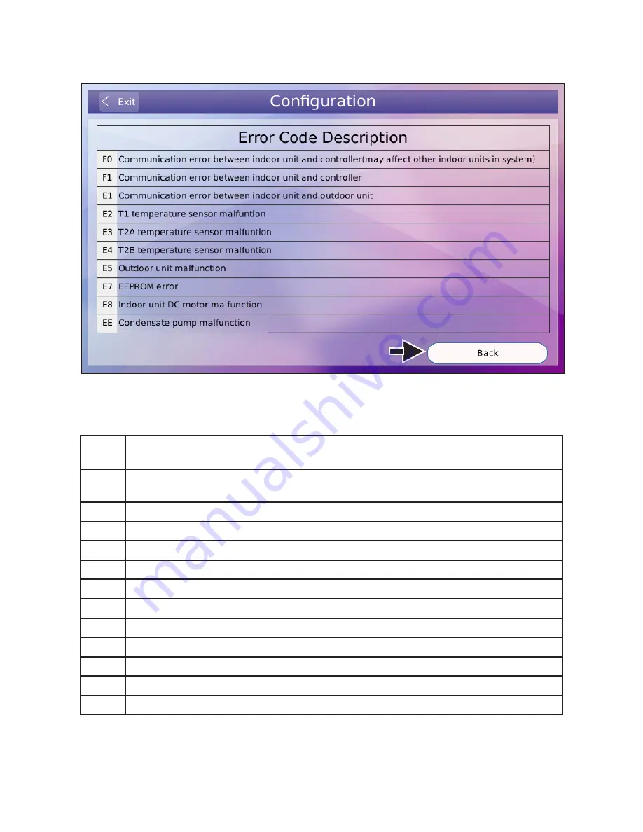
3.  Tap the back button to return to the error code history screen.

Figure 47. View Error Code Description from Controller

Complete List of Error Code Descriptions

Error   

Code

Description

F0

Communication error between the indoor unit and the wired controller (may affect 

other indoor units in the system)

F1

Communication error between the indoor unit and the controller

F2

Controller EEPROM error

E1

Communication error between the indoor unit and the outdoor unit

E2

T1 temperature sensor error

E3

T2A temperature sensor error

E4

T2B temperature sensor error

E5

Outdoor unit error

E6

Fan motor error

E7

Indoor unit EEPROM error

E8

Indoor unit DC motor error

EE

Condensate pump error

Summary of Contents for V0STAT51P-2

Page 1: ...Lithium battery 2 Phillips screws 2 Plastic spacers 2 1 8 polymer toggle anchors 1 Installation and operation manual Requirements Be sure that power supply has been turned off before beginning install...

Page 2: ...ller Information 42 View Error Code History 43 Complete List of Error Code Descriptions 44 Service 45 Set System Type 46 Set Temperature Unit 47 Set Temperature Setpoint Range 48 Set Fan Control 49 Ad...

Page 3: ...between indoor units Minimum 18 AWG stranded shielded cable Installation CAUTION Do not install controller in areas where harmful gases containing sulfur or other damaging agents may exist or the cont...

Page 4: ...le shielding at the indoor unit 3 Use stranded shielded 18 GA cable Figure 1 Connect Controller to Single Indoor Unit Wiring Connections Connecting to One Indoor Unit Connect the controller to one ind...

Page 5: ...the same outdoor unit NOTES 1 Connect R 12V on the controller to terminal 12V on the first indoor unit only 12V connection provides power to controller connection to multiple indoor units will damage...

Page 6: ...the Controller 1 Remove the back cover from the controller See Figure 3 Figure 4 Attach Back Cover to Wall Figure 3 Remove Back Cover from Controller 2 Attach the back cover to the wall using screws S...

Page 7: ...o the bottom snap joints of the back cover at an angle See Figure 5 Figure 5 Insert Controller into Back Cover 4 Push the controller back toward the wall until it snaps into place See Figure 6 Figure...

Page 8: ...8 Home Screen Display Figure 7 Standard Home Screen Display Figure 8 Simple Home Screen Display 1 15 14 13 10 2 3 4 5 6 7 8 9 10 2 3 4 5 6 7 8 9 12 11 1 12 11...

Page 9: ...tpoint 8 Fan speed Tap High Med or Low to change the fan speed 9 Room temperature Displays the room temperature 10 Date Time Displays the current date and time 11 Centralized controller lock icon not...

Page 10: ...r units connected to a local controller may also be controlled by a centralized control ler Indoor units respond to the last command sent It is recommended that indoor units be con trolled from a sing...

Page 11: ...ion Tap the Cool button to start cooling operation The indoor unit will pro vide cooling operation to maintain the selected setpoint The default setpoint range is 62 F to 86 F 17 C to 30 C Figure 10 C...

Page 12: ...ode Operation Heating Mode Operation Tap the Heat button to start heating operation The indoor unit will pro vide heating operation to maintain the selected setpoint The default setpoint range is 62 F...

Page 13: ...or heating setpoints display on the Home screen The current operation mode setpoint displays larger than the non current operation mode To adjust the setpoint of either cooling or heating while in Aut...

Page 14: ...14 Figure 13 Dry Mode Operation Dry Mode Operation Tap the Dry button to start dry mode operation Fan speed cannot be ad justed during dry mode...

Page 15: ...15 Figure 14 Fan Only Mode Operation Fan Only Operation Tap the Fan button to start fan only operation The indoor unit fan operates without heating or cooling...

Page 16: ...16 Fan Speed Tap High Med or Low to change the fan speed Figure 15 Fan Speed Operation...

Page 17: ...t the setpoint of the current mode by dragging the temperature slider or by tapping the Increase or Decrease buttons The default setpoint range is 62 F to 86 F 17 C to 30 C The setpoint range can be a...

Page 18: ...room temperature displays on the controller s main screen The room temperature is sensed by the sensor inside the controller default or by the indoor unit Set the sensor location using the Room Tempe...

Page 19: ...to enable or disable the indoor unit automatic louver swing function The swing icon changes to indicate if swing is on or off Set the louver swing functionality using the Louver screen in the Service...

Page 20: ...Schedule button to access the schedule program Figure 19 Tap Schedule Button to access Schedule Program NOTE If schedules are used and a centralized controller is installed on the system controller fu...

Page 21: ...ptions Table 2 Schedule Options Schedule Description Everyday Set the schedule independently for each day of the week 5 1 1 Set the schedule uniformly for Monday through Friday and independently for S...

Page 22: ...22 3 Tap the blank space in the grid to set the first action A set of default values will display Figure 21 Display Timer Information...

Page 23: ...et or modify the event parameters including the action begin time ON OFF mode cooling temperature setting heating temperature setting and fan speed 6 Tap the OK button to save the settings 7 Tap the D...

Page 24: ...24 Figure 24 Edit Schedule Actions Events 8 Up to 8 timer actions events can be scheduled for each day...

Page 25: ...25 Copy and Paste a Schedule 1 Select the day you want to copy and tap the Copy button A red triangle displays on the day that is selected for copying Figure 25 Select Day to Copy From...

Page 26: ...26 2 Select the day to copy to and tap the Paste button Figure 26 Select Day to Copy To...

Page 27: ...27 Setup Holidays Schedule Holiday scheduling overrides the set schedule settings on those days 1 Tap the Holidays button to access the holiday schedule settings Figure 27 Setup Holidays Schedule...

Page 28: ...28 2 Tap the blank space in the grid and then tap the Edit button Figure 28 Edit Holiday Schedule...

Page 29: ...Ex 18th Janu ary 2016 4 Select the By Day button to select the holiday by month and week Ex 3rd Monday in Janu ary 5 Tap the OK button to save the holiday schedule settings 6 Tap the Delete button to...

Page 30: ...30 Reset Weekly Timer Parameters 1 Tap the Reset button to permanently delete all schedules This cannot be undone Figure 30 Reset Schedule...

Page 31: ...schedule for a set period of time At the end of the override time period system operation returns to the scheduled operation Override is only avail able when a schedule has been set 1 Tap the Activat...

Page 32: ...32 Figure 32 Override Time Period 2 Select the amount of time for the override Options are 30 60 90 or 120 minutes 3 To hide the time period buttons tap the Override button again or wait 5 seconds...

Page 33: ...aced by the indoor unit address and error code If multiple indoor units have errors occur simultaneously the codes will scroll on the home screen If one indoor unit has multiple errors simultaneously...

Page 34: ...can be locked by a centralized controller The centralized controller lock icon displays when the controller is being locked by the central ized controller Functions locked by the centralized controlle...

Page 35: ...ature Locks the lower limit regulation action for the setpoint temperature in cooling dehumidifying mode or the cooling setpoint temperature in auto mode on the controller Lock the upper limit of heat...

Page 36: ...36 General Settings Configuration Access the settings menu by tapping the Menu button gear icon on the Home screen Figure 35 Access Settings Menu...

Page 37: ...that is displayed on the controller screen 1 Tap the Menu button on the Home screen and then tap the Date button 2 Use the up arrows and down arrows to set the date 3 Tap the Save button to save the s...

Page 38: ...enu button on the Home screen and then tap the Time button 2 Time is displayed in 12 hour format by default 3 Tap the Use 24 hour format checkbox to display 24 hour time 4 Tap the Save button to save...

Page 39: ...button on the Home screen and then tap the Schedule button 2 Tap the Schedule Enable button to enable the schedule function 3 Tap the Schedule Disable button to disable the schedule function 4 Tap the...

Page 40: ...hen tap the Daylight Saving Time button 2 Tap the Enable button to enable daylight savings time function 3 Tap the Disable button to disable daylight savings time function NOTE The 2nd Sunday in March...

Page 41: ...and then tap the Display Menu button on the Home screen 2 Tap the Simple Display button to enable simple display mode Only displays frequently used functions 3 Tap the Standard Display button to enab...

Page 42: ...d Controller Informa tion button Figure 44 Contractor and Controller Information Figure 45 Enter Contractor Information 2 To edit the contractor information tap to the right of any of the Contractor I...

Page 43: ...Tap the Menu button on the Home screen and then tap the Error Code Display button The last ten error codes display If the indoor unit has multiple simultaneous errors they will be displayed on the sa...

Page 44: ...ion error between the indoor unit and the wired controller may affect other indoor units in the system F1 Communication error between the indoor unit and the controller F2 Controller EEPROM error E1 C...

Page 45: ...n on the Home screen and then swiping right on the Service button Use the keypad to enter your password The user password can be changed on the Lock screen within the Service Configuration Op tions Th...

Page 46: ...Tap the Service button and then enter your password 3 Tap the System Type button 4 Tap the Heat Pump button to identify the system as a heat pump system The auto mode functionality will not display on...

Page 47: ...nd operate the system in degrees Celsius Figure 51 Set Temperature Unit NOTE The indoor unit temperature unit display must be set at the same time as the controller Indoor units default to display tem...

Page 48: ...mits for the cooling setpoint During auto cooling or dry mode the temperature setpoint cannot be set lower than this value 5 Tap the up arrow and down arrow buttons to set limits for the heating setpo...

Page 49: ...oling setpoint is satisfied NOTE The default setting Fan On is recom mended for highest efficiency 5 Heating Tap the Fan ON button default to make the indoor unit fan con tinue to run when the heating...

Page 50: ...et the running parameters of auxiliary or alternative heat connected through the HHE Relay Kit Four Dry Contact board 1 Tap the Menu button on the Home screen 2 Tap the Service button and then enter y...

Page 51: ...xt to Heater ON temperature in the Auxiliary heat area to display optional temperatures 3 F 5 F in Fahrenheit or 2 C 3 C in Celsius Tap to select a tem perature value This temperature option indicates...

Page 52: ...F 15 F 20 F 25 F 30 F 35 F 40 F and OFF in Fahrenheit or 14 C 12 C 9 C 7 C 4 C 1 C 2 C 4 C and OFF in Celsius Tap to select a temperature value When the outdoor temperature is lower than the selected...

Page 53: ...to indicate the function is locked 5 Tap the function button again to unlock that function Figure 58 Set Lock Function Lock Category Description ON OFF Locks the turning on off function of the contro...

Page 54: ...n on the Home screen 2 Tap the Service button and then enter your password 3 Tap the Lock button 4 Tap the Change Password button 5 Use the keypad to enter the current password then the new password N...

Page 55: ...d 3 Tap the Room Temperature Sensor Location button 4 Tap the Controller button to select the indoor temperature sensor of the controller 5 Tap the Indoor Unit button to select the indoor temperature...

Page 56: ...the sensor location screen The correction ranges from 4 F to 4 F or 2 C to 2 C 1 Tap the Menu button on the Home screen 2 Tap the Service button and then enter your password 3 Tap the Room Temperatur...

Page 57: ...o select from all of the over ride periods leave all buttons unselected 1 Tap the Menu button on the Home screen 2 Tap the Service button and then enter your password 3 Tap the Override button 4 Tap t...

Page 58: ...e screen 2 Tap the Service button and then enter your password 3 Tap the Louver button 4 Tap the No button if any of the connected indoor unit do not have auto swing louvers The Swing button of the Ho...

Page 59: ...59 Configure ERV Settings Future Revision 1 This function is reserved for a future revision of the controller Do not adjust default setting Figure 65 Identify Indoor Unit as Energy Recovery Ventilator...

Page 60: ...r code history and HHE Relay four dry contact status 1 Access the Advanced Information screen by tapping the Menu button on the Home screen Then tap the Service button and enter your password 2 Tap th...

Page 61: ...then enter your password 3 Tap the Advanced Information button 4 The Operating Data screen displays 5 Tap the up and down arrows to switch between address numbers of connected indoor units and view t...

Page 62: ...ator T2B Temperature in the outlet of the indoor unit evaporator EXV Position Openness of the indoor unit electronic expansion valve posi tion Unit Step ON OFF On off status Mode Operation mode Cool s...

Page 63: ...p the Error Code button The last ten error codes display If the indoor unit has multiple simultaneous errors they will be displayed on the same row Each row can display up to six error codes Tap the E...

Page 64: ...Tap the Menu button on the Home screen 2 Tap the Service button and then enter your password 3 Tap the Advanced Information button 4 Tap the Dry Contacts button 5 Tap the up and down arrows to switch...

Page 65: ...screen 2 Tap the Service button and enter your password 3 Tap the Firmware and Setting button Figure 70 Firmware and Setting Information IMPORTANT After initial setup make a back up copy of the contro...

Page 66: ...er software revision 1 Tap the Menu button on the Home screen 2 Tap the Service button and then enter your password 3 Tap the Firmware and Setting button 4 Tap the Copy Change Settings or Update Firmw...

Page 67: ...rvice button and then enter your password 3 Tap the Firmware and Setting button 4 Tap the Copy Change Settings or Update Firmware button A popup screen displays 5 Tap the Copy Setting To USB button 6...

Page 68: ...hen enter your password 3 Tap the Firmware and Setting button 4 Tap the Copy Change Settings or Update Firmware button A popup screen displays 5 Tap the Upload Setting From USB button 6 A popup displa...

Page 69: ...soft ware from the connected USB device 1 Tap the Menu button on the Home screen 2 Tap the Service button and then enter your password 3 Tap the Firmware and Setting button 4 Tap the Copy Change Sett...

Page 70: ...ll the most recent software update even if you are behind more than one revision 5 Tap the Software Update button 6 Select the appropriate update file from the displayed list 7 Tap the OK button to co...

Page 71: ...This cannot be undone 1 Tap the Menu button on the Home screen 2 Tap the Service button and enter your password 3 Tap the Reset Settings button on the left panel 4 Tap the Reset Settings button in the...

Page 72: ...n 62 F Max 86 F Indoor Fan Cooling Fan ON Heating Fan ON AUX AH Heater Contact Auxiliary heat 3 F Alternative heat OFF Lock No function locked Room Temperature Sensor Location Controller Room Temperat...

Reviews: