


Page 19
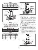
TYPICAL PIPE CONNECTIONS
TRANSITION
2”
2”
2”
3”
2”
2”
or
DO NOT transition from smaller
to larger pipe size in horizontal
runs of exhaust pipe.
TOP VIEW
EXHAUST
INTAKE
* When transitioning up in pipe size, use the shortest length of 2” PVC pipe possible.
NOTE − Exhaust pipe and intake pipe must be the same diameter.
*2”
TRANSITION
2”
1−1/2”
070 Only
DO NOT transition
from larger to smaller
pipe in horizontal runs
of exhaust pipe.
Exhaust
Exhaust
FIGURE 21
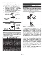
Flue Coupling
The provided flue coupling must be attached to the exhaust
coupling on the furnace top panel. Use provided bands. See
steps below and FIGURE 22.
1 -
Remove the caution tag from the flue coupling.
2 -
Fully insert flue coupling with both bands loosely
attached on the furnace exhaust coupling.
3 -
Insert PVC exhaust pipe through flue coupling. Ensure
vent pipe is fully seated into exhaust coupling.
4 - Tighten both top and bottom bands
(do not use glue
or silicone to attach)
to 40in-lbs.
Furnace
Top Band
(torque to 40in-lbs)
PVC
Exhaust Pipe
Top Panel
Flue Coupling To Exhaust Coupling
Bottom Band
(torque to 40in-lbs)
Flue Couplig
Furnace
Exhaust Coupling
FIGURE 22
Summary of Contents for SIGNATURE SLP99DF070V36
Page 40: ...Page 40 FIGURE 49...


