


Page 11
Figure 15
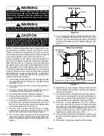
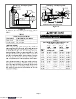
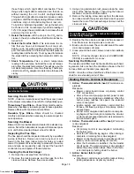
Oil Piping − One-Pipe System
ÓÓÓÓÓÓÓÓÓÓÓ
ÓÓÓÓÓÓÓÓÓÓÓ
ÓÓÓÓÓÓÓÓÓÓÓ
ÓÓÓÓÓÓÓÓÓÓÓ
ÓÓÓÓÓÓÓÓÓÓÓ
ÓÓÓÓÓÓÓÓÓÓÓ
ÓÓÓÓÓÓÓÓÓÓÓ
ÓÓÓÓÓÓÓÓÓÓÓ
ÓÓÓÓÓÓÓÓÓÓÓ
ÓÓÓÓÓÓÓÓÓÓÓ
AIR VENT
FILL PIPE
OIL
TANK
FUEL PUMP
AUX
FILTER
SHUT−OFF
VALVE
8 ft (2.4 m)
Maximum
One Pipe Lift
To determine the correct tubing size for piping, refer to
table 3 .
Table 3
One−Pipe Oil Line Sizing
Line Length
Pipe Diameter (OD Tubing)
0−50’ (15 m)
3/8" (10 mm)
51−100’ (15 m)
1/2" (12 mm)
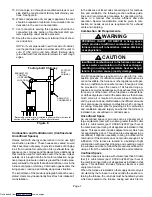
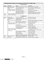
Two−Pipe System
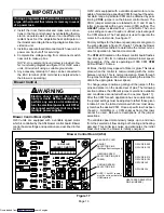
When using a two−pipe system (see figure 16) with the oil
tank below the level of the burner, use a single−stage fuel
pump in lift conditions of up to 10 feet (3 m) and/or a vacu-
um of 10" (254 mm) Hg or less. Use a two−stage fuel pump
when lift exceeds 10 feet (3 m) and/or a vacuum of 10" (254
mm) Hg to 15" (381 mm) Hg. Both conditions require that
you use of a two−pipe system, which consists of a return
line that purges the fuel pump of air by returning it to the
tank. To determine the run and lift for piping, refer to table 4
.
Use continuous lengths of heavy wall copper tubing or
steel pipe for oil supply pipe. Install oil supply pipe under
floor or near walls to protect it from damage. Avoid running
pipes along joists or reverberating surfaces. Always use
flare fittings. All fittings must be accessible. Do not use
compression fittings.
Figure 16
ÓÓÓÓÓÓÓÓÓÓÓÓÓÓ
ÓÓÓÓÓÓÓÓÓÓÓÓÓÓ
ÓÓÓÓÓÓÓÓÓÓÓÓÓÓ
ÓÓÓÓÓÓÓÓÓÓÓÓÓÓ
ÓÓÓÓÓÓÓÓÓÓÓÓÓÓ
RETURN
PIPE
OIL
TANK
RETURN
PIPE
H
3"−4"
(76 mm −102 mm)
R
outside tank fuel pump above bottom of tank.
Oil Piping − Two-Pipe System
AIR VENT
FILL PIPE
FUEL PUMP
AUX
FILTER
INLET
IMPORTANT
Both oil supply and return pipes must be sub-
merged in oil in the supply tank.
Table 4
Two−Pipe Maximum Pipe Length (H + R)
3450 RPM − 3 GPH (11.4 LPH)
Lift H"
ft (m)
Single−
Stage
Two−
Stage
Single−
Stage
Two−
Stage
3/8" (10 mm) OD
Tubing − ft (m)
1/2" (12 mm) OD
Tubing
0’ (0.0)
84 (25.6)
93 (28.3)
100 (30.5)
100 (30.5)
2’ (0.6)
73 (22.3)
85 (25.9)
100 (30.5)
100 (30.5)
4’ (1.2)
63 (19.2)
77 (23.5)
100 (30.5)
100 (30.5)
6 ’ (1.8)
52 (15.8)
69 (21.0)
100 (30.5)
100 (30.5)
8’ (2.4)
42 (12.8)
60 (18.3)
100 (30.5)
100 (30.5)
10’ (3.0)
31 (9.4)
52 (15.9)
100 (30.5)
100 (30.5)
12’ (3.7)
21 (6.4)
44 (13.4)
83 (25.3)
100 (30.5)
14’ (4.3)
−−−
36 (11.0)
41 (12.5)
100 (30.5)
16’ (4.9)
−−−
27 (8.2)
−−−
100 (30.5)
18’ (5.5)
−−−
−−−
−−−
76 (23.2)
Downloaded from


