


Page 14
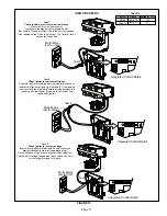
B-Heating Components
Combustion air inducer (B6), primary limit control (S10),
SureLight ignitor, burners, flame rollout switch (S47), gas
valve (GV1), combustion air prove switch (S18), and clam
shell heat exchangers are located in the heating compart
ment. The heating compartment can be accessed by re
moving the burner access panel.
1. Flame Rollout Switches (Figure 10)
Flame rollout switches S47 are SPST N.C. high tempera
ture limits located on the top left and bottom right of the front
buner box plate. S47 is wired to the burner ignition control
A92. When either of the switches sense flame rollout (indi
cating a blockage in the combustion passages), the flame
rollout switch trips, and the ignition control immediately
closes the gas valve. Switch S47 in all ML195UH units is
factory preset to open at 210
_
F + 12
_
F (99
_
C + 6.7
_
C) on a
temperature rise. All flame rollout switches are manual re
set.
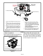
2. Primary Limit Control (Figure 12)
Primary limit (S10) used on ML195UH units is located in the
heating vestibule panel. When excess heat is sensed in the
heat exchanger, the limit will open. Once the limit opens,
the furnace control energizes the supply air blower and de-
energizes the gas valve. The limit automatically resets
when unit temperature returns to normal. The switch is fac
tory set and cannot be adjusted. For limit replacement re
move wires from limit terminals, remove mounting screws,
rotate limit switch 90 degrees and slowly remove from the
vestibule panel. Install replacement limit with same care.
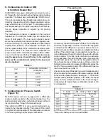
3. Burners (Figure 11)
All units use inshot burners. Burners are factory set and do
not require adjustment. Burners can be removed as an as
sembly for service. Burner maintenance and service is de
tailed in the MAINTENANCE section of this manual. Each
burner uses an orifice which is precisely matched to the
burner input. See table 7 for orifice size. The burner is sup
ported by the orifice and will easily slide off for service. A
flame retention ring in the end of each burner maintains
correct flame length and shape and keeps the flame from
lifting off the burner head.
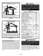
TABLE 7
Gas Orifice Size
Unit
Fuel
Orifice Size
All
Natural
0.063
All
L.P./Propane
0.0340
FIGURE 11
Burner Detail Top View
FLAME SENSOR
IGNITOR
ORIFICES
4. Heat Exchanger (Figure 12)
ML195UH units use an aluminized steel primary and stain
less steel secondary heat exchanger assembly. Heat is
transferred to the air stream from all surfaces of the heat
exchanger. The shape of the heat exchanger ensures
maximum efficiency.
The combustion air inducer pulls fresh air through the burn
er box. This air is mixed with gas in the burners. The gas /
air mixture is then burned at the entrance of each clam
shell. Combustion gases are then pulled through the pri
mary and secondary heat exchangers and exhausted out
the exhaust vent pipe.
FIGURE 12
Primary Limit Location and Heat Exchanger
Install limit face down
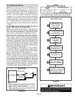
5. Gas Valve (GV1)
The ML195UH uses an internally redundant valve to as
sure safety shut‐off. If the gas valve must be replaced, the
same type valve must be used.