background image

Page 25

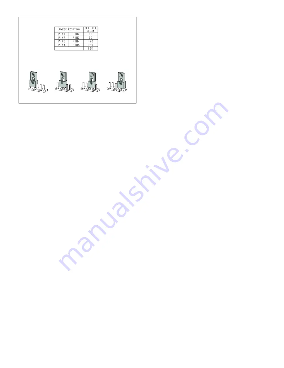
HEAT FAN

OFF TIME IN SECONDS

To adjust fan-off timing, reposition jumper across pins to

achieve desired setting.

NO JUMPER

60 90

120 180

60 90

12

0

180

60 90

12

0

180

60 90

12

0

18

0

60 Second 

off Time

90 Second 

off Time

120 Second 

off Time

180 Second 

off Time

FIGURE 23 

Blower Speeds

Follow the steps below to change the blower speeds.

1 -  Turn off electrical power to furnace.
2 -  Remove blower access panel.
3 -   Disconnect existing speed tap at integrated control 

speed terminal.

See unit Product Specifications Manual for indoor blower

data.

NOTE - 

Termination of any unused motor leads must be 

insulated.

4 -   

Place unused blower speed tap on integrated 

control “PARK” terminal or insulate.

5 -   Refer to blower speed selection chart on unit wiring 

diagram for desired heating or cooling speed. See 

Blower performance data beginning on the next 

page.

6 -   Connect selected speed tap at integrated control 

speed terminal.

7 -  Resecure blower access panel.
8 -  Turn on electrical power to furnace.
9 -  Recheck temperature rise.

Twinning 2 ML180DF Furnaces

The control board in this furnace is equipped with a provi-

sion to ”twin” (interconnect) two(2) adjacent furnaces with 

a common plenum such that they operate as one (1) large 

unit.
When twinned, the circulating blower speeds are synchro-

nized between the furnaces. If either furnace has a need 

to run the blower, both furnaces will run the blower on the 

same speed. The cooling speed has highest priority, fol-

lowed by heating speed and fan speed.
Field installation of twinning consists of connecting wires 

between the ”C” and ”Twin” terminals of the two controls. 

The 24 VAC secondary of the two systems must be in 

phase. All thermostat connections are made to one con-

trol only. Figure 24 show wiring for two-stage and single 

stage thermostats.
The twinned furnace without thermostat connections is 

to have the call for heat supplied by an external 24VAC 

isolation relay to prevent its rollout switch from being by-

passed by the other twinned furnace. The coil of the iso-

lation relay connects from the thermostat ”W” to 24 VAC 

common. The contacts of the relay connect ”R” to ”W” on 

the non-thermostat twin.

Summary of Contents for ML180DF045P24A

Page 1: ...rvice or maintenance can cause property damage personal injury or loss of life Installation and service must be performed by a licensed professional HVAC installer or equivalent service agency or the gas supplier 2017 Lennox Industries Inc Dallas Texas USA MERIT SERIES GAS FURNACE DOWNFLOW AIRDISCHARGE Contents Unit Dimensions 2 ML180DF Gas Furnace 3 Shipping and Packing List 3 Safety Information ...

Page 2: ... Right 7 1 8 181 Left 5 3 8 137 Right 2 3 16 56 Left 33 838 AIR FLOW 3 4 19 19 7 16 494 9 16 14 B Supply Air Supply Air 9 16 14 9 16 14 3 1 8 79 9 16 14 9 16 14 19 7 16 494 3 4 19 Model No A B C D in mm in mm in mm in mm ML180DF045P24A ML180DF045P36A ML180DF070P36A 14 1 2 368 13 3 8 340 13 330 4 3 4 121 ML180DF090P36B ML180DF090P48B 17 1 2 446 16 3 8 416 16 406 6 1 4 159 ML180DF110P60C 21 533 19 7...

Page 3: ...11 West 42nd Street New York NY 10036 Clearances Adequate clearance must be made around the air open ings into the vestibule area In order to ensure proper unit operation combustion and ventilation air supply must be provided according to the current National Fuel Gas Code Vent installations must be consistent with the Na tional Fuel Gas Code venting tables in this instruction and applicable provi...

Page 4: ...aintained during construction Air filters must be replaced upon construction com pletion The input rate and temperature rise must be set per the furnace rating plate One hundred percent 100 outdoor air must be provided for combustion air requirements during construction Temporary ducting may supply out door air to the furnace Do not connect duct directly to the furnace Size the temporary duct foll...

Page 5: ...stion and to prevent a downdraft Insufficient air causes incomplete combustion which can result in carbon monoxide CAUTION Insufficient combustion air can cause headaches nausea dizziness or asphyxiation It will also cause excess water in the heat exchanger resulting in rusting and premature heat exchanger failure Excessive exposure to contaminated combustion air will result in safety and performa...

Page 6: ...s 305 mm of the top of the enclosure and one opening within 12 inches 305 mm of the bottom See figure 2 Air from Outside If air from outside is brought in for combustion and ventila tion the confined space must have two permanent open ings One opening shall be within 12 inches 305 mm of the top of the enclosure and one opening within 12 inches 305 mm of the bottom These openings must communi cate ...

Page 7: ...openings shall each have a free area of at least one square inch 645 mm2 per 4 000 ment in the enclosure CHIMNEY OR GAS VENT WATER HEATER OUTLET AIR VENTILATION LOUVERS Each end of attic INLET AIR Ends 12 in above bottom FURNACE AIR FLOW FIGURE 4 EQUIPMENT IN CONFINED SPACE ALL AIR FROM OUTSIDE OUTLET AIR INLET AIR WATER HEATER CHIMNEY OR GAS VENT NOTE Each air duct opening shall have a free area ...

Page 8: ...e furnace and the floor The base must be ordered separately See table 2 for opening size to cut in floor CAUTION The furnace and downflow combustible flooring base shall not be installed directly on carpeting tile or other combustible material other than wood flooring SUPPLY AIR PLENUM DOWNFLOW COMBUSTIBLE FLOORING BASE PROPERLY SIZED FLOOR OPENING FIGURE 7 TABLE 2 COMBUSTIBLE FLOOR OPENING SIZE C...

Page 9: ...down flow position only Do not install the furnace horizon tally Select a location that allows for the required clearances that are listed on the unit nameplate Also consider gas supply connections electrical supply vent connection and installation and service clearances 24 inches 610 mm at unit front The unit must be level NOTE Units with 1 3HP and 1 2HP blower motors are equipped with three flex...

Page 10: ...the inlet air opening The inlet air opening must be sized to accommodate the maximum volume of exhausted air as well as the maximum volume of combustion air required for all gas appliances serviced by this space WARNING Improper installation of the furnace can result in personal injury or death Combustion and flue products must never be allowed to enter the return air system or the living space Us...

Page 11: ...ategory I furnace is an appliance equipped with an integral mechanical means to either draw or force combustion products through the combustion chamber and or heat exchanger NOTE Use these instructions as a guide They do not supersede local codes This furnace must be vented ac cording to all local codes these installation instructions and the provided venting tables in these instructions The venti...

Page 12: ...o the capacity requirements shown in the provided venting tables OTHER APPLIANCE FURNACE 5 ft 1 5 m minimum AIR FLOW FIGURE 16 DO NOT insulate the space between the liner and the chimney wall with puffed mica or any other loose granular insulating material IMPORTANT SINGLE appliance venting of a fan assisted furnace into a tile lined masonry chimney interior or outside wall is PROHIBITED The chimn...

Page 13: ...s NOTE Single Wall Vent Connectors may be used if the requirements set forth by the National Fuel Gas Code are met Please consult latest edition of NFPA 54 ANSI Z223 1 for proper sizing and application TABLE 4 Connector Diameter inches mm Maximum Horizontal Connector Length feet m 3 76 4 1 2 1 37 4 102 6 1 83 5 152 7 1 2 2 29 6 152 9 2 74 7 178 10 1 2 3 20 9 If the common vertical vent is offset t...

Page 14: ...0 227 6 25 46 36 91 47 149 59 223 8 0 0 84 0 165 0 276 0 415 2 12 57 16 109 25 178 28 263 5 23 53 32 103 42 171 53 255 8 28 49 39 98 51 164 64 247 10 0 0 88 0 175 0 295 0 447 2 12 61 17 118 23 194 26 289 5 23 57 32 113 41 187 52 280 10 30 51 41 104 54 176 67 267 15 0 0 94 0 191 0 327 0 502 2 11 69 15 136 20 226 22 339 5 22 65 30 130 39 219 49 330 10 29 59 40 121 51 206 64 315 15 35 53 48 112 61 19...

Page 15: ...ce Input Rating in Thousands of Btu Per Hour FAN FAN FAN NAT FAN FAN FAN NAT FAN FAN FAN NAT FAN FAN FAN NAT 6 92 81 140 116 204 161 309 248 8 101 90 155 129 224 178 339 275 10 110 97 169 141 243 194 367 299 15 125 112 195 164 283 228 427 352 20 136 123 215 183 314 255 475 394 30 152 138 244 210 361 297 547 459 Removal of the Furnace from Common Vent In the event that an existing furnace is remove...

Page 16: ...ler than unit gas connection CAUTION If a flexible gas connector is required or allowed by the authority that has jurisdiction black iron pipe shall be installed at the gas valve and extend outside the furnace cabinet The flexible connector can then be added between the black iron pipe and the gas supply line Gas Supply 1 This unit is shipped standard for left or right side installation of gas pip...

Page 17: ...50 32 56 985 27 89 873 24 72 791 22 39 728 20 61 677 19 17 635 17 98 600 17 00 2 50 8 2 067 52 502 4020 113 83 2760 78 15 2220 62 86 1900 53 80 1680 47 57 1520 43 04 1400 39 64 1300 36 81 1220 34 55 1160 32 844 2 1 2 63 5 2 469 67 713 6400 181 22 4400 124 59 3530 99 95 3020 85 51 2680 75 88 2480 70 22 2230 63 14 2080 58 89 1950 55 22 1840 52 10 3 76 2 3 068 77 927 11300 319 98 7780 220 30 6250 176...

Page 18: ...ped with a field make up box on the left hand side of the cabinet The make up box may be moved to the right side of the furnace to facilitate installation If the make up box is moved to the right side clip the wire ties that bundle the wires together The excess wire must be pulled into the blower compartment Secure the excess wire to the existing harness to protect it from damage INTERIOR MAKE UP ...

Page 19: ...energized in the heating mode when the combustion air inducer is op erating Any humidifier rated up to one amp can be connected to this terminal with the neutral leg of the circuit being con nected to one of the provided neutral terminals If a hu midifier rated at greater than one amp is connected to this terminal it is necessary to use an external relay relay Generator Use Voltage Requirements Th...

Page 20: ...Page 20 Figure 20 ML180DF Schematic Wiring Diagram ...

Page 21: ...tch closed with combustion air inducer de en ergized 3 Flashes Pressure switch open with combustion air inducer ener gized 4 Flashes Primary limit switch open 5 Flashes Rollout switch open 6 Flashes Pressure switch cycle lockout 7 Flashes Lockout burners fail to light 8 Flashes Lockout buners lost flame too many times 9 Flashes Line voltage polarity incorrect Note This control is equipped with a p...

Page 22: ...e which automatically lights the burners Do not try to light the burners by hand 5 Remove the access panel 6 Move switch on gas valve to OFF Do not force See figure 22 7 Wait five minutes to clear out any gas If you then smell gas STOP Immediately call your gas supplier from a neighbor s phone Follow the gas supplier s instructions If you do not smell gas go to next step 8 Move switch on gas valve...

Page 23: ...hut off all other gas appliances connected to meter Supply Pressure Measurement A threaded plug on the inlet side of the gas valve provides access to the supply pressure tap Remove the threaded plug install a field provided barbed fitting and connect a manometer to measure supply pressure Furnace should operate at least 5 minutes before checking supply pres sure See table 11 for proper supply pres...

Page 24: ...adjustment Flame Rollout Switch The manually reset switch is located on the front of the burner box Pressure Switch The pressure switch is located in the heating compartment adjacent to the combustion air inducer The switch checks for proper combustion air inducer operation before allow ing ignition trial The switch is factory set and requires no adjustment Temperature Rise After the furnace has b...

Page 25: ...power to furnace 9 Recheck temperature rise Twinning 2 ML180DF Furnaces The control board in this furnace is equipped with a provi sion to twin interconnect two 2 adjacent furnaces with a common plenum such that they operate as one 1 large unit When twinned the circulating blower speeds are synchro nized between the furnaces If either furnace has a need to run the blower both furnaces will run the...

Page 26: ...Gas fumes which could contain carbon monoxide can be drawn into living space resulting in personal injury or death Annual Furnace Maintenance At the beginning of each heating season and to comply with the Lennox Limited Warranty your system should be checked by a licensed professional technician or equiva lent as follows 1 Check wiring for loose connections voltage at indoor unit and amperage of i...

Page 27: ...3 Clock gas meter to ensure that the unit is operating at the specified firing rate Check the supply pressure and the manifold pressure On two stage gas furnaces check the manifold pressure on high fire and low fire If manifold pressure adjustment is necessary consult the Service Literature for unit specific information on adjusting gas pressure Not all gas valves are adjustable Verify correct tem...

Page 28: ...vice must be performed by a licensed professional installer or equivalent service agency or gas supplier Cabinet Parts Upper access panel Blower panel Top cap Control Panel Parts Transformer Integrated control Door interlock switch Circuit breaker Blower Parts Blower wheel Blower housing Motor Motor mounting frame Motor capacitor Blower housing cutoff plate Heating Parts Flame sensor Heat exchange...

Reviews: