Lennox LGH420 User'S Information Manual Download Page 6

Page 5

REMOVE FILTERS

FIGURE 4

Lubrication

All motors are lubricated at the factory. No further
lubrication is required.

Blower shaft bearings are prelubricated. For extended
bearing life, relubricate at least once every two years
with a lithium base grease, such as Alvania 3 (Shell Oil),
Chevron BRB2 (Standard Oil) or Regal AFB2 (Texas
Oil). Use a hand grease gun for relubrication. Add only
enough grease to purge through the bearings so that a
bead of grease appears at the seal lip contacts.

Manifold Pressures

Manifold pressures are shown in table 1. Refer to figures
1 and 2 to locate pressure ports.

TABLE 1

MANIFOLD PRESSURES 

in.wg. (kPa)

Unit

Natural Gas

Propane (LP) Gas

1st Stage

+ 0.2(+.05)

2nd Stage

+ 0.3(+.08)

1st Stage

+ 0.2(+.05)

2nd Stage

+ 0.3(+.08)

420-600

1.6 (0.40)

3.7 (0.92)

5.5 (1.37)

10.5(2.61)

See Optional Modulating Gas Valve (MGV) section on
units equipped with MGVs.

Burners

1- Periodically examine burner flames for proper

appearance during the heating season.

2- Inspect the position of the flame sensor. Sensor

should be centered in the path of the flame.

3- Before each heating season examine the burners for

any deposits or blockage which may have occurred.
Clean burners as follows.

4- Turn off the electrical power and gas supply to the unit

and open heat section access panel.

5- Remove and retain two screws securing burners to

the burner support. See figure 5. Clean as necessary.
Replace burners and secure with retained screws.


WARNING

Danger of explosion. Can cause injury or
death. Do not overtighten main burner
mounting screws. Snug tighten only.
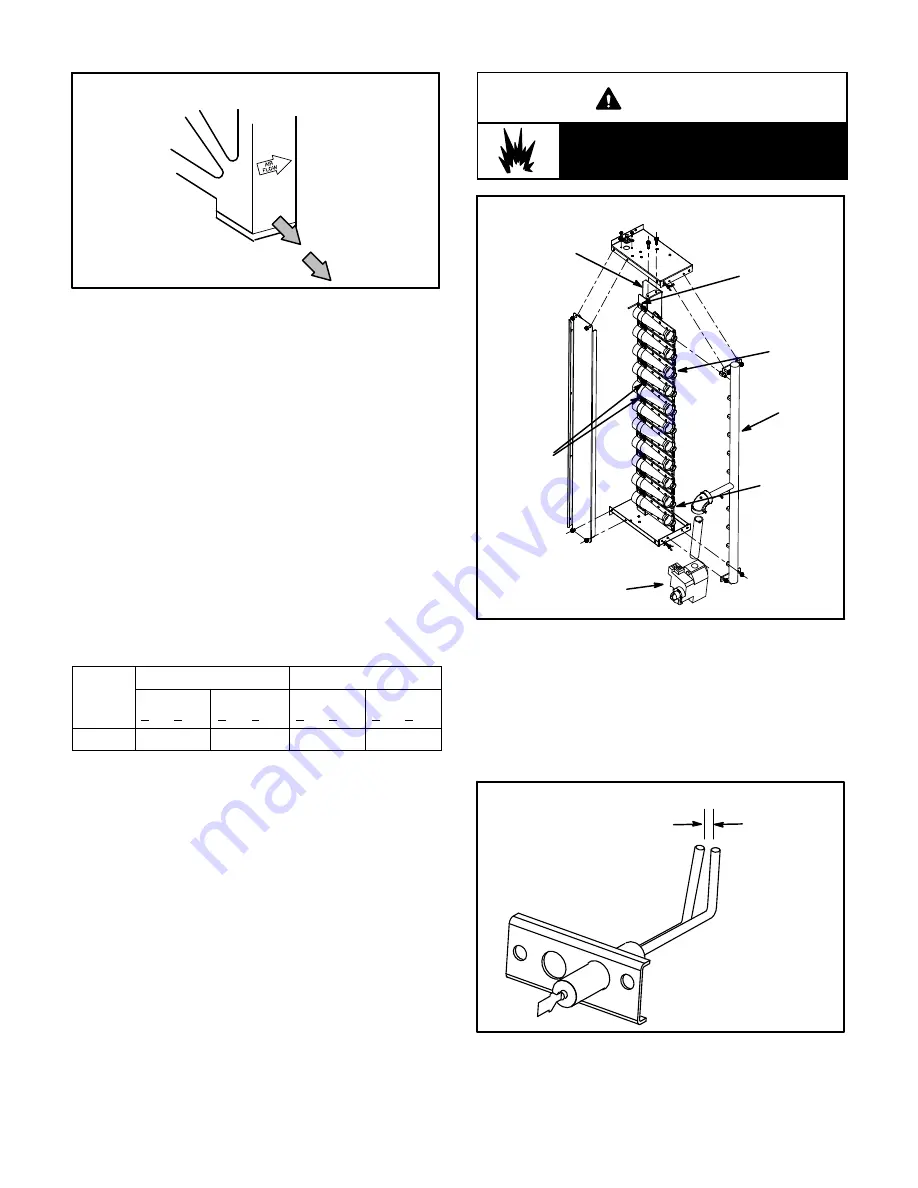
BURNER BOX ASSEMBLY

FIGURE 5

GAS

MANIFOLD

FLAME

SENSOR

GAS

VALVE

BURNERS

REMOVE
SCREWS

TO CLEAN

BURNERS

BURNER

SUPPORT

IGNITOR

6- Remove and retain the two screws securing the

ignitor to the burner support. Remove the burner and
check the spark gap with appropriately sized twist
drills or feeler gauges. See figure 6.

7- Replace the ignitor and secure in place with retained

screws.

FIGURE 6

IGNITOR

SPARK GAP

SHOULD BE 1/8”

(3mm)

8- Restore electrical power and gas supply. Follow

lighting instructions attached to unit and use
inspection port in access panel to check flame.

Summary of Contents for LGH420

Page 1: ...t be per formed by a qualified installer ser vice agency or the gas supplier D Do not try to light any appliance D Do not touch any electrical switch do not use any phone in your building D Immediately call your gas supplier from a neighbor s phone Follow the gas supplier s instructions D If you cannot reach your gas supplier call the fire department D Extinguish any open flames ROOFTOP UNITS READ...

Page 2: ...PTIONAL BURNERS GAS VALVES 2 CONDENSER COILS 4 CONTROL BOX COMPRESSORS 4 CONDENSER FANS 6 BLOWERS FILTERS ELEVEN 16 x 25 x 2 406 x 635 x 51mm OR 16 X 25 X 4 406 X 635 X 102mm ECONOMIZER OPTIONAL ENERGY RECOVERY WHEEL OPTIONAL FILTER DRIERS LGH420 480 540 600 PARTS ARRANGEMENT LOUVERS OPTIONAL ...

Page 3: ... and protective clothing WARNING Danger of electrical shock explosion and fire Improper servicing could result in dangerous operation serious inujry death or property damage WARNING Do not use this furnace if any part has been under water A flood damaged furnace is extremely dan gerous Attempts to use the furnace can result in fire or explosion A qualified service agency should be contacted to ins...

Page 4: ...ll gas STOP Immediately call your gas supplier from a neighbor s phone Follow the gas supplier s instructions If you do not smell gas go to the next step 7 Turn gas valve switch to ON See figure 1 On Honeywell VR8305Q gas valves turn the knob on the gas valve counterclockwise to ON Do not force See figure 2 8 Close or replace the heat section access panel 9 Turn on all electrical power to applianc...

Page 5: ... Service To maintain efficiency and longevity your equipment must be serviced yearly by a qualified service technician Failure to provide proof of service can void warranty CAUTION Label all wires prior to disconnection when ser vicing controls Wiring errors can cause improper and dangerous operation Verify proper operation after servicing Servicing Filter Units are equipped with eleven 16 X 25 X ...

Page 6: ...nspect the position of the flame sensor Sensor should be centered in the path of the flame 3 Before each heating season examine the burners for any deposits or blockage which may have occurred Clean burners as follows 4 Turn off the electrical power and gas supply to the unit and open heat section access panel 5 Remove and retain two screws securing burners to the burner support See figure 5 Clean...

Page 7: ...lue box cover Clean the flue box with a wire brush as required 3 Clean the tubes with a wire brush 4 Reassemble the unit The flue box cover gasket and combustion air inducer gasket should also be replaced during reassembly Service Reminder Call a qualified service technician if the unit is inoperative Before calling always check the following to be sure service is required 1 Be sure electrical dis...

Page 8: ... maximum heating input 3 Measure the manifold pressure at the gas valves Manifold pressures should be GV1 GV3 Natural 4 0 w c LP 10 8 w c GV4 GV5 Natural 3 7 w c LP 10 5 w c 4 Turn the OPT2 switch OFF The unit will operate at minimum heating input 5 Measure the manifold pressure at the gas valves Manifold pressures should be GV1 GV3 Natural 4 0 w c LP 10 8 w c GV4 GV5 Natural 0 9 w c LP 2 6 w c FI...

Reviews: