background image

• 29 •

1

2

3

4

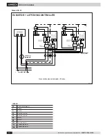
P=8

bar max

0
°

6
0
°

1

4

3

2

Installation, operation and maintenance / 

INALTO-IOM-1809-E

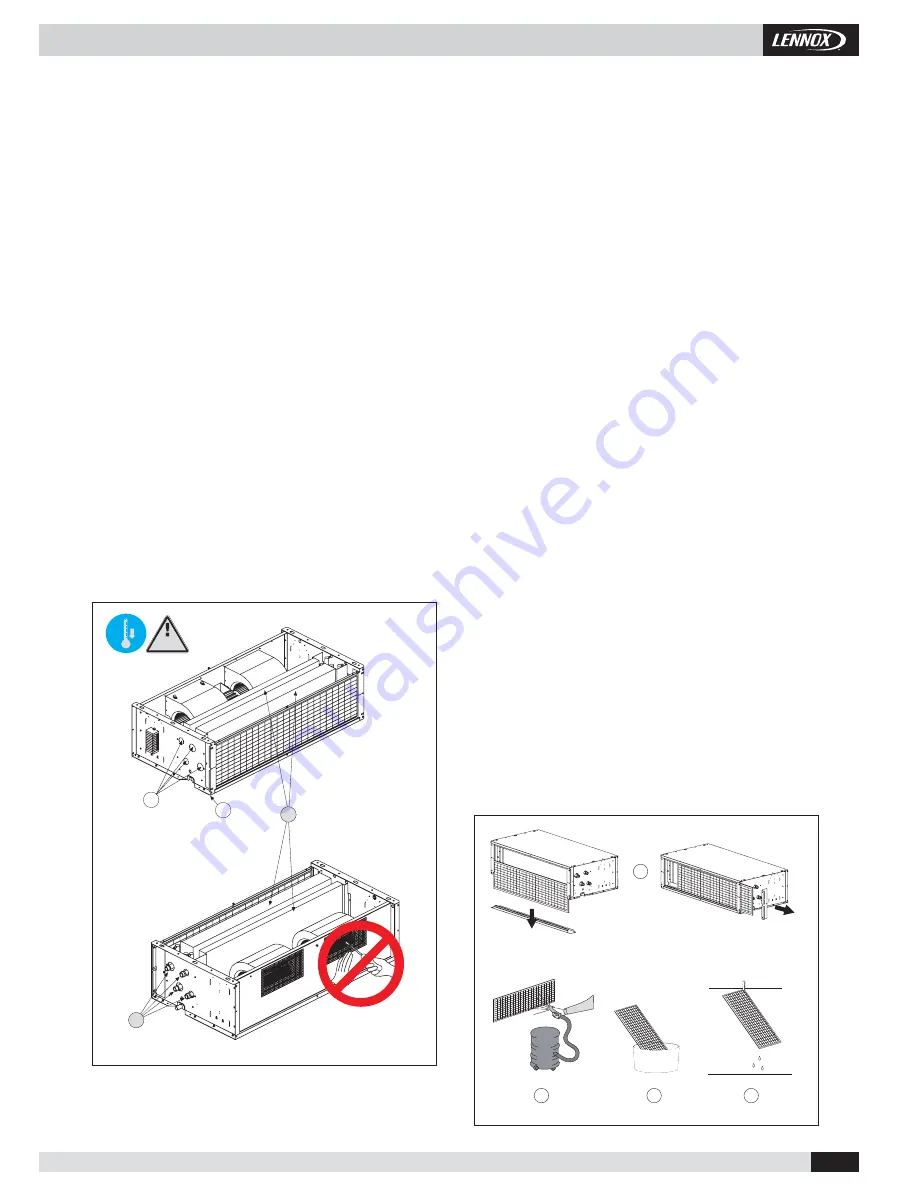
TURNING THE COIL

CAUTION

The fan wheels may reach the speed of 1,000 rpm. Do not insert objects 
into the electric fan and certainly not hands. The motor becomes hot during 
operation; wait for it to cool before touching it. During the heating mode of 
operation the exchanger and the connecting pipes may become very hot 
(80°C). Wait for the exchanger to cool before touching it or protect hands 
with suitable gloves. The heat exchange water coils are suitable for work-
ing up to a maximum pressure of 8 bar.

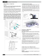
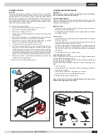
To turn the coil, proceed as follows:

1.   Disconnect the terminal board (6) from the side of the unit.
2.   Remove the condensate collecting tray (2).
3.   Remove the coil 

fi

 xing screws (5).

4.   Take out the coil (3), being careful not to be cut by the 

fi

 ns and not to 

damage them.

5.   Remove the knockouts (1) on the opposite side of the unit (using a 

screwdriver) to allow the coil connections to pass through.

6.   Position the coil, turning it without tipping it upside down, so that the  

fi

 ttings are in line with the holes left by the knockouts.

7.   Fix the coil using the previously removed screws (5).
8.   Shift the terminal board (

fi

 xing it to the side opposite the water 

fi

 t-

tings) and the motor cables, 

fi

 xing them with their clamps. Ensure 

that the cables pass through the hole in the side of the unit, protecting 
them with the relative grommet. If it proves easier to carry out this 
operation by separating the wires from the terminal board, mark the 
positions of the wires to avoid making mistakes when reconnecting.

9.   Reconnect the wires to the relative terminal board (6), taking care 

that they are correctly positioned.

10.  Replace the condensate collecting tray (2).

Pic. 41

CLEANING AND MAINTENANCE

CAUTION
Before carrying out any cleaning or maintenance work, disconnect 
the unit from the mains electricity supply!

ROUTINE MAINTENANCE

The user is duty bound to have all maintenance operations carried out by 
trained and quali

fi

 ed personnel only. If the unit has to be dismantled, pro-

tect hands with work gloves.

Monthly checks:

- Ensure that the fan impellers are clean. If they are dirty, clean them by 

suction so as not to damage them.

- Check the whole of the electrical part and in particular that the electrical 

connections are tight.

Yearly checks:

- Check the whole of the electrical part and in particular that the electrical 

connections are tight.

- Check the tightness of all the bolts, nuts and whatever else may be 

loosened by the constant vibrations of the unit.

- Check the motor for dust, dirt or other impurities. Periodically check that 

the motor works without unusual vibrations or noise and that the fan 
inlet is not obstructed, which could otherwise leading to overheating of 
the windings.

- Check the fans for dirt or any foreign matter.

CLEANING THE AIR FILTER

The unit is 

fi

 tted with an air 

fi

 lter on the fan inlet. During normal operation 

the 

fi

 lter holds back impurities in the air.

The 

fi

 lter should be cleaned periodically to keep its 

fi

 ltering properties and 

the air

fl

 ow to the fan unchanged.

It is advisable to clean the 

fi

 lter at least once a month, proceeding as fol-

lows.

1. Take out the 

fi

 lter.

2. Place the 

fi

 lter on a 

fl

 at, dry surface and remove the accumulated dust 

with a vacuum cleaner.

3. Wash the 

fi

 lter with water and detergent (no solvents).

4. Leave the 

fi

 lter to dry in a ventilated place in the sun.

5. Replace the 

fi

 lter when it is perfectly dry.

Please clean the air fi lter every working season of the unit or more 
frequently considering the unit activity.

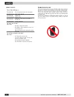
NOTE: the fi lter may also be taken out from the side or from the top.

Pic. 42

Summary of Contents for INALTO

Page 1: ...TION OPERATION AND MAINTENANCE DUCTABLE AIR TREATMENTUNIT INALTO 2581 27851 W 381 5668 m3 h INALTO IOM 1809 E LENNOX participates in the ECP programme for FCU Check ongoing validity of certificate www...

Page 2: ...ns and technical data Installation Example of accessories use and compatibility Assembly diagrams Hydraulic connection Wiring diagrams 3 speed motor 3 speed motor LXTFF01M controller EC motor EC motor...

Page 3: ...eriods make sure that the controls are in the position 0 off If the unit is not going to be used in winter when temperatures are near to freezing drain the system and ensure that the unit heat exchang...

Page 4: ...00 5 E 118 118 118 195 195 F 93 5 93 5 118 5 131 143 5 G 233 233 233 310 310 I 83 5 83 5 108 5 121 133 5 N 193 193 193 270 270 1 2 1 2 3 4 3 4 1 1 2 3 4 3 4 1 1 3 4 3 4 1 1 1 1 4 kg 28 38 49 62 Instal...

Page 5: ...5 E 201 5 201 5 F 131 5 144 G 311 311 I 121 5 134 N 270 270 1 1 1 1 4 1 1 2 1 1 2 1 1 2 kg Installation operation and maintenance INALTO IOM 1809 E SIZE Fittings male 2 rows coil 4 rows coil 6 rows c...

Page 6: ...e INSTALLATION OF THE AIR TREATMENT UNIT PRELIMINARY OPERATIONS check that the various unit components are perfectly intact check that the installation accessories and documentation are in the pack pl...

Page 7: ...stallation operation and maintenance INALTO IOM 1809 E EXAMPLE OF ACCESSORIES USE AND COMPATIBILITY UNIT Aluminium damper Air intake grill Air supply grill Depending on the requirements the air filter...

Page 8: ...nged with corrugated washer DIN4161 Sizes 49 57 x10 Screw TC M5x12 UNI7687 x6 Hex nut M5 flangiato with corrugated washer DIN4161 Size 05 to 28 x8 Screw TC M5x12 UNI7687 x6 Hex nut M5 flanged with cor...

Page 9: ...w TE M5x12 UNI 5739 Sizes 49 57 x6 Screw TC M5x12 UNI7687 x6 Hex nut M5 flanged with corrugated washer DIN4161 x4 Screw TE M5x12 UNI 5739 Size 05 to 28 x7 Screw TC M5x12 UNI7687 x6 Hex nut M5 flanged...

Page 10: ...enance INALTO IOM 1809 E MOUNTING BRACKET PAM MOUNTING BRACKET RAM Size 05 to 28 x6 Self drilling screw with tip TC 3 9x9 5 UNI6954 Size 05 to 28 x6 Self drilling screw with tip TC 3 9x9 5 UNI6954 Fig...

Page 11: ...C M5x12 UNI7687 x4 Hex nut M5 flanged with corrugated washer DIN4161 Size 05 to 28 x8 Screw TC M5x12 UNI7687 x6 Hex nut M5 flanged with corrugated washer DIN4161 Sizes 49 57 x10 Screw TC M5x12 UNI7687...

Page 12: ...rrugated washer DIN4161 Sizes 49 57 x10 Screw TC M5x12 UNI7687 x6 Hex nut M5 flanged with corrugated washer DIN4161 Size 05 to 28 x8 Screw TC M5x12 UNI7687 x6 Hex nut M5 flanged with corrugated washer...

Page 13: ...UNI7687 x6 Hex nut M5 flanged with corrugated washer DIN4161 Size 05 to 28 x5 Screw TC M5x12 UNI7687 x4 Hex nut M5 flanged with corrugated washer DIN4161 Sizes 49 57 x6 Screw TC M5x12 UNI7687 x4 Hex...

Page 14: ...DIN4161 Sizes 49 57 x10 Screw TC M5x12 UNI7687 x10 Hex nut M5 flanged with corrugated washer DIN4161 Size 05 to 28 x8 Screw TC M5x12 UNI7687 x8 Hex nut M5 flanged with corrugated washer DIN4161 Sizes...

Page 15: ...IAGRAM Size 05 to 28 x6 Self drilling screw TC 4 2x13 UNI8118 Sizes 49 57 x8 Self drilling screw TC 4 2x13 UNI8118 SUPPLY GRILL ON RAM ASSEMBLY DIAGRAM Size 05 to 28 x6 Self drilling screw TC 4 2x13 U...

Page 16: ...IAGRAM Size 05 to 28 x6 Self drilling screw TC 4 2x13 UNI8118 Sizes 49 57 x8 Self drilling screw TC 4 2x13 UNI8118 INTAKE GRILL ON RAM ASSEMBLY DIAGRAM Size 05 to 28 x6 Self drilling screw TC 4 2x13 U...

Page 17: ...er It is advisable for a trap to be fitted The condensate drain pipe should be connected to a rainwater drainage system Do not use sewage systems to avoid possible rising of odours in the event of eva...

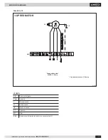
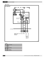
Page 18: ...OM 1809 E Size 05 to 15 LEGEND Earth yellow green Common Minimum speed Medium speed Maximum speed Capacitor Motor Electric box with terminal board for fan speed control M1 Pic 29 Fan speed control 230...

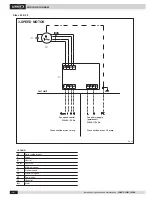
Page 19: ...speed control 230VAC 50 Hz Fan power supply permanent 230VAC 50 Hz Cross section area 1 5 mmq Cross section area 1 mmq UNIT LIMIT LEGEND Earth yellow green Phase Neutral Common Minimum speed Medium sp...

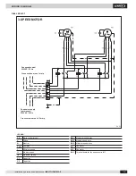
Page 20: ...2 5 mmq Fan speed control 230VAC 50 Hz Fan power supply permanent 230VAC 50 Hz LEGEND Earth yellow green Phase Neutral Common Minimum speed Medium speed Maximum speed Capacitor Capacitor Maximum speed...

Page 21: ...09 E Size 05 to 15 LEGEND Earth yellow green Common Minimum speed Medium speed Maximum speed SDP power chart ACCESSORY NECESSARY Capacitor Motor Terminal board for fan speed control M1 Pic 32 Cross se...

Page 22: ...O IOM 1809 E Sizes 25 28 Cross section area 1 5 mmq UNIT LIMIT LXTFF01M LEGEND PE Earth yellow green L Phase N Neutral Com Common I Minimum speed II Medium speed III Maximum speed A2 SDP power chart C...

Page 23: ...LEGEND Earth yellow green Phase Neutral Common Minimum speed Medium speed Maximum speed Capacitor Capacitor Maximum speed relay Medium speed relay Minimum speed relay Fan motor Fan motor Terminal boa...

Page 24: ...peration and maintenance INALTO IOM 1809 E Size 05 to 15 LEGEND Earth yellow green Electronic control Motor Terminal board Pic 35 EC MOTOR FAN SPEED CONTROL 0 10 Vdc 2x0 5mmq POWER SUPPLY PERMANENT 23...

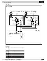
Page 25: ...Sizes 25 28 LEGEND PE Earth yellow green L Phase N Neutral A1 Electronic control M1 Motor XA1 Terminal board TH1 Thermal protector Pic 36 EC MOTOR UNIT LIMIT FAN SPEED CONTROL 0 10 Vdc 2x0 5mmq shield...

Page 26: ...Earth yellow green Phase Neutral Electronic control Electronic control Motor Motor Terminal board Thermal protector Thermal protector Sizes 49 57 Pic 37 EC MOTOR UNIT LIMIT FAN SPEED CONTROL 0 10 Vdc...

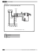
Page 27: ...O IOM 1809 E Size 05 to 15 Pic 38 EC MOTOR LXTFZ01M CONTROLLER 1112 UNIT LIMIT LXTFZ01M LEGEND PE Earth yellow green A1 Electronic control M1 Motor XA1 Terminal board Shielded and twisted cable 2x0 50...

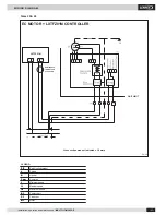
Page 28: ...LEGEND PE Earth yellow green L Phase N Neutral Com Common I Minimum speed II Medium speed III Maximum speed A1 Power chart C1 Capacitor M1 Motor Pic 39 EC MOTOR LXTFZ01M CONTROLLER UNIT LIMIT LXTFZ01...

Page 29: ...EC MOTOR LXTFZ01M CONTROLLER LEGEND Earth yellow green Phase Neutral Electronic control Electronic control Motor Motor Terminal board Thermal protector Thermal protector LXTFZ01M LIMITE DELLA MACCHINA...

Page 30: ...densate collecting tray 2 Pic 41 CLEANING AND MAINTENANCE CAUTION Before carrying out any cleaning or maintenance work disconnect the unit from the mains electricity supply ROUTINE MAINTENANCE The use...

Page 31: ...as before Check that the filter and the coil are clean no air has entered the water circuit by blee ding from the relative valve the installation is correctly balanced the boiler chiller is in proper...

Page 32: ...0 20 lennoxemea com Given the continued commitment of Lennox in producing quality products specifications features and dimensions are subject to change without notice and any liability is declined Imp...

Reviews: