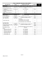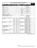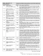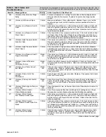
background image

506566−01 09/10

Page 14

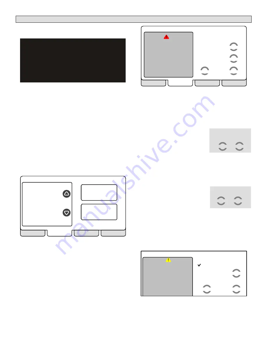
Viewing and clearing Installer Alerts

NOTE −  If the following screen appears, check all wiring for
correct connections.

Thermostat is unable  to

communicate to system

components

Please contact local

service technician.

Possible cause is a wiring fault

Figure 35. Communication failure screen

As described earlier on Page 4, alerts may pop up on the
screen during setup. Details of all active alerts can only be ac-
cessed through the installer’s screens. To view all alerts pres-
ent at any time, press the 

alerts 

tab. Up to 10 alerts are stored

for recall by the technician.

The left side of the main alert screen shows a list of each com-
municating device discovered in the system and includes
model and serial number information. The up/down arrows al-
low you to scroll through the list of discovered devices. The
selected device is shown in bold lettering.

On the right side of the alert screen, press 

view active alerts

(see figure 36) to list all active alerts for either SYSTEM
ALERTS (lists alerts from all communicating devices) or a se-
lected device. If there are no alerts, the display will show
There are no new alerts that require service".

view active

alerts

view cleared

alerts

system devices

Use the arrows to

select a device

alerts

diagnostics

EXIT

ALL SYSTEM
ALERTS

HP
XP17−036−230−01
5910M12345

Furnace
SLP98UH−
090V36C−01
5910G17546

Figure 36. System devices alerts

Press 

view cleared alerts

 to list previously active alerts that

were cleared by the device or installer. Until at least one alert
has been cleared by the device or the installer, the message
There are no new alerts that require service" will be dis-
played.

The first alert will be displayed in the Device alert" screen
(figure 37), in order of:

1. critical first (red icon),
2. service next (yellow icon).

If the information in the alert box exceeds the box size, press

press for more

 to see the remaining information.

next alert

back

clear

remind later

alert description

ALERT 1 of 5 
Moderate Alert Code : 120
Thermostat reports:
Unresponsive
Indoor Unit
Latest Occurrence
09/04/10
04:28 PM
1 Occurrences

     press for more

active alerts

alerts

diagnostics

EXIT

Figure 37. Device alert

Clearing alerts

critical alert

 (red icon) identifies a system or device issue

that can prevent the system from working properly or at all,
and if allowed to run, could cause damage to the system. The
issue raised by the alert must be addressed before clearing
the alert.

Press 

clear 

(see figure 37) to begin

clearing a critical alert; then 

confirm

the request (shown to the right). The
device will respond to the request in-
dicating whether or not the alert can
be cleared at that time.

If an alert cannot be cleared, revisit the alert issue and make
repairs accordingly.

The 

edit date

 option is not available for a critical alert.

service alert 

(yellow icon) reminds users to service filters,

humidifier pad, UV light and PureAir

 Air Purification system.

Press 

clear 

(see figure 37) 


to begin

clearing a service alert. If you answer

no

 to the was action taken" screen

(shown to the right), the alert re-
appears and is not cleared.

Action must be taken. You must either perform the mainte-
nance required to clear the alert or edit the time to again be
reminded (described later).

If you press 

yes 

to ’was action taken?’, the


Set new alert

date" screen (figure 38) appears. You may chose from the list
of options or set a custom time (see figure 40).

set time for next reminder

disabled

3 months

6 months
12 months
24 months
custom time

alert description

ALERT 1 of 5 
Service Alert
Thermostat reports:
Replace Filter 1
Latest Occurrence
09/04/10
04:28 PM
4 Occurrences

     press for more

cancel

set

select

Figure 38. Set new alert date

press ’confirm’ to clear the

alert, or press ’cancel

confirm

cancel

was action taken?

yes

no

Summary of Contents for icomfort Touch

Page 1: ...System Settings 4 Setting Time and Date 5 Adding Removing Non Communicating Devices 6 Humidification Dehumidification Modes 9 Modifying Communicating Device Settings 10 Using the Test Features tests tab 11 Setting up Equipment Parameters equipment tab 12 Stage Delay Timers Differentials equipment tab 12 Using the Diagnostic Features diagnostics tab 13 Viewing and Clearing Alerts alerts tab 14 Acce...

Page 2: ...tat via the RSBus Integrated Furnace Control IFC Communicating control for furnace IFC controls ignition CAI and blower and moni tors all safety features in the unit Memory Fault Recall Method of checking for stored errors Non Communicating Any device in the HVAC system that is NOT icomfort enabled and is NOT discoverable and does not communicate with the thermostat via the RSBus Programming Tabs ...

Page 3: ... of heat two stages of compressor operation Two stages of heat pump heating and two stages of aux iliary back up heat are provided Also two stages of emergency heat are provided supports Indoor Air Quality with time based notification of consumables including media filters UVC bulbs hu midifier pads and PureAir system catalyst service re placement supports variable capacity multi stage heat cool u...

Page 4: ...g fault Figure 4 Alert window System settings figure 5 appear first As you use the up down arrows to scroll through the settings the right hand side will show the current value For example Current Value 35 shows the current setting of the Circulate Fan ON time Daylight Saving Time Circulate Fan ON Time Dealer Name Dealer Address system settings to adjust a setting high light it then press edit Cur...

Page 5: ...Figure 8 Set current time and date NOTE After setting the time and date if you don t need to add any non communicating devices you may wish to accept the default system parameters and skip forward to tests To do so repeatedly press next step on each screen until you get to the tests screen From there you can check the sys tems operation Thereafter should you need to change a communicating device p...

Page 6: ...lue Not Installed back edit Figure 11 Installing non communicating outdoor unit Outdoor Unit Type default is underlined current value is checked save cancel Not Installed 1 Stage A C Unit 2 Stage A C Unit Figure 12 Defining non communicating outdoor unit type 3 Change any red settings e g Outdoor Unit Capacity by selecting the setting and press edit Use up down arrows to make changes then press sa...

Page 7: ...n outdoor temperature sensor you will not have a option for Dew Point Control mode If you do not have the ability to select or adjust the Humid ity RH setpoint on the Indoor Humidity tab the control is set for Display Only In the installer program go the equipment tab and select System 49W95 and press the edit button Select Humidification Control Mode and press edit Choose Basic Precision or Dew P...

Page 8: ...ation Control Mode default is underlined current value is checked save cancel Figure 18 Selecting Humidification Dehumidifica tion mode Depending on the type of equipment installed the lists of op tions may be different than those shown in figure 18 In order for either or both of these controls to display in the indoor hu midity section of the user interface the selected option must be other than ...

Page 9: ...quires NOTE Systems using icomfortt and a dehumidifier De hum jumper on furnace air handler control does not need to be cut outdoor sensor must be installed and set up dehumidification has been enabled on installer settings and the unit is in COOL mode or if in AUTO at least one ther mostat cooling call made prior to the dehumidification de mand and a dehumidification demand exists RH above set po...

Page 10: ...the red message disappears High Heating Airflow High Cooling Airflow Airflow Profile Cooling setup HELP Furnace edit back reset please view and save all red settings Current Value 1100 CFM Figure 24 Modified device screen If you select reset and then confirm the highlighted device in this example the Furnace will be reset to its factory set ting You would see a screen similar to figure 25 referenc...

Page 11: ...ou may then use select to select a second test a third and so on start select setup tests equipment HELP selected tests TEST ALL select tests to run TEST ALL remove Figure 27 Start running tests Also note that there are now two buttons along the bottom labeled remove and start Use remove to deselect a se lected test If you prefer to run tests one at a time use the arrows to high light a desired te...

Page 12: ...quipment tab use the arrows to select 1st Stage Differential Press edit Use the up down arrows to adjust to the desired setting and press save 2nd Stage Differential where applicable The default is 1 0 F but can be programmed between 0 5 and 8 0 F in 0 5 F increments 3rd Stage Differential through 6th Stage Differential where applicable The default is 0 5 F but can be pro grammed between 0 5 F and...

Page 13: ...P98UH 090V36C 01 5910G17546 Thermostat 49W95 A110A00070 Figure 33 Select device to run diagnostics Use the arrow buttons to scroll through the list of items found on the left of the screen Then press select The right side of the screen shows which item is selected figure 34 Use start to begin the process The screen will show DIAGNOSTICS IN PROGRESS briefly then change to show the list of val ues a...

Page 14: ... yellow icon If the information in the alert box exceeds the box size press press for more to see the remaining information next alert back clear remind later alert description ALERT 1 of 5 Moderate Alert Code 120 Thermostat reports Unresponsive Indoor Unit Latest Occurrence 09 04 10 04 28 PM 1 Occurrences press for more active alerts alerts diagnostics EXIT Figure 37 Device alert Clearing alerts ...

Page 15: ...ice Alert Thermostat reports Replace Filter 1 Latest Occurrence 09 04 10 04 28 PM 4 Occurrences press for more Figure 41 Remind later options After selecting a reminder time using the listed options or a custom time press set The Remind later confirmation screen will appear figure 42 remind later set for 6 10 10 10 19AM alert description done ALERT 1 of 5 Service Alert Thermostat reports Replace F...

Page 16: ...Lennox equipment in staller warning screen appears Figure 46 Press yes to pro ceed no returns to the home screen WARNING The following screens are intended for use by qualified Lennox equipment installers only Do you want to proceed yes no Figure 46 Qualified Lennox equipment installer warning When you press yes the thermostat s processor will search for communicating devices in the system The nex...

Page 17: ...ing the thermostat will have retained set tings from the previous configuration If a device has been re placed and re configuration has detected its replacement de vice it will know the original device is missing and prompt the installer figure 50 If this is the initial configuration the Compatible device found screen does not appear Missing Device Equipment Type No Model No control model no Seria...

Page 18: ...program set points The SSR set point will be displayed on the thermostat The SSR set point calculation is as follows Current SSR CSP Current Program CSP Target Program CSP Current SSR HSP Current Program HSP Target Program HSP N N For New SSR HSP For New SSR CSP Where CSP Cool Set Point HSP Heat Set Point N number of 30 second intervals to the target program set point Note N 240 when target progra...

Page 19: ...eration will satisfy the heating demand rather that the more expen sive auxiliary electric heat The high and low balance points will not lock out both compressor heat and auxiliary heat fur nace at the same time Again the Balance Points feature is only available if an outdoor sensor is installed standard on icomfort enabled heat pumps Dual Fuel Applications Communicating Systems Only Dual fuel app...

Page 20: ...st stage provides 70 of full capacity 2nd stage provides 100 of full capacity Three stage heat 1st stage provides 60 of full capacity 2nd stage provides 80 of full capacity 3rd stage provides 100 of full capacity Four stage heat 1st stage provides 35 or 40 of full capac ity 2nd stage provides 60 of full capacity 3rd stage pro vides 80 of full capacity 4th stage provides 100 of full ca pacity Table...

Page 21: ... 5ºF 0 5 to 8ºF 0 5ºF 4th Stage Differential 0 5ºF 0 5 to 8ºF 0 5ºF 5th Stage Differential 0 5ºF 0 5 to 8ºF 0 5ºF 6th Stage Differential 0 5ºF 0 5 to 8ºF 0 5ºF Stage Delay Timers Enabled Enabled Disabled 2nd Stage Delay 20 Minutes 5 to 120 Minutes 5 Min 3rd Stage Delay 20 Minutes 5 to 120 Minutes 5 Min 4th Stage Delay 20 Minutes 5 to 120 Minutes 5 Min 5th Stage Delay 20 Minutes 5 to 120 Minutes 5 ...

Page 22: ...endent on the tonnage of the unit 5CFM Low Cooling Airflow 5CFM High Cooling Airflow 5CFM Cooling Airflow Profile 1 1 No Delays 2 ON No delays OFF 45 sec delay 3 ON 82 7 5min OFF No delays 4 ON 50 30s 82 7 5min OFF 50 30s Low Heating Airflow nnnn CFM See Note 3 at end of table NOTE CFM Default and Values Settings are de pendent on the tonnage of the unit 5CFM High Heating Airflow 5CFM Continuous I...

Page 23: ...25 450 25 Heating Airflow Control Type 0 70 000 BTU 1 2 HP fan 500 675 25 90 000 BTU 1 2 HP fan 425 625 25 90 000 BTU 1HP fan 625 875 25 110 000 BTU 1 HP fan 750 1025 25 135 000 BTU 1HP fan High Heating Airflow CFM 100 heat DIP SW 800 1100 25 Heating Airflow Control Type 0 70 000 BTU 1 2 HP fan 925 1250 25 90 000 BTU 1 2 HP fan 1025 1425 25 90 000 BTU 1HP fan 1350 1850 25 110 000 BTU 1 HP fan 1500...

Page 24: ...CFM 25 1 HP blower Other Parameters Equipment Name Furnace N A N A N A None Up to 35 characters Continuous Indoor Blower Airflow DIP SW See Note 3 below Min CFM Max CFM 25 None 1 2 HP blower Min CFM Max CFM 25 1 HP blower Humidification Airflow Same as above Min CFM Max CFM 25 Humidifier present 1 2 HP blower Min CFM Max CFM 25 1 HP blower Dehumidification Airflow Percentage 140 70 120 60 160 80 2...

Page 25: ...tensity 100 20 to 100 20 Outdoor Temp Dis play Disabled Disabled Enabled Indoor Humidity Dis play Enabled Disabled Enabled Filter 1 Timer Disabled Disabled 3 Months 6 Months 12 Months 24 Months Custom Time Filter 1 Timer Disabled Disabled 3 Months 6 Months 12 Months 24 Months Custom Time Humidifier Pad Tim er Disabled Disabled 3 Months 6 Months 12 Months 24 Months Custom Time UV Bulb Timer Disable...

Page 26: ...tions Ohm wires If fault persists then cycle pow er Fault clears after communication is restored 32 Stat Asynchronous Reset any unit Moder ate Indicated unit is resetting itself Check power connections and check 24VAC voltage at DEVICE The alarm is only cleared by pressing the clear button on the Installer Alerts Tab If fault persists after checking con nections replace board 34 Stat Must Program ...

Page 27: ... or cooling is not avail able Only applicable in the communicating mode not in startup Exit from Commissioning and Execute Set Factory Default mode Control will still operate on default parameter settings 132 Air Handler Failed Flash CRC Check Check Sum Software is corrupted Critical Recycle power If failure re occurs replace control System reset is re quired to recover 180 Furnace Air Handler Out...

Page 28: ...on and restriction Resumes normal opera tion after fault is cleared 228 Furnace Inducer Pressure Switch Calibration Failure Moder ate Unable to perform pressure switch calibration Check vent system and pressure switch wiring connections Resumes normal operation after fault is cleared 240 Furnace Low Flame Current Run Mode Moder ate Check micro amperes of flame sensor using control diagnostics or f...

Page 29: ...or if necessary Cleared in Commu nicating mode 30 seconds after fault recovered In Non Communicating mode Cleared after the current heat call is completed 311 Furnace Heat Firing Rate Reduced to Match Airflow Minor Warning Only Furnace blower in cutback mode due to restricted airflow Reduce firing rate every 60 seconds to match available CFM Check filter and duct system To clear replace filter if ...

Page 30: ...Circuit Critical Required amount of current is not passing through Start current transform er Clears the error after 1 normal compressor run cycle 405 Outdoor Unit LSOM Open Compressor Run Circuit Critical Required amount of current is not passing through Run current transform er Clears the error after 1 normal compressor run cycle 406 Outdoor Unit Compressor con tactor welded Critical Compressor ...

Page 31: ...ded 704 Stat Comfort Sensor Humidity Too High Moder ate Recalibrate thermostat to clear Replace thermostat if needed 705 Stat Comfort Sensor Humidity Too Low Moder ate Recalibrate thermostat to clear Replace thermostat if needed OHM CHECK Ohm reading between i and i anywhere on the RSBus with supply power off should be between 70 and 90 ohms If above 90 ohms check and repair wiring splices or othe...

Page 32: ...ize an outdoor sensor or the system is not a heat pump 7 icomfort thermostat does not show a choice for Dew Point Control Humidification mode only Basic and Precision choices Dew Point Control will only be displayed if the system has an outdoor sensor Add an outdoor sensor to the system and connect to the outdoor sensor terminals on the indoor unit icomfort system is not able to read the outdoor t...

Page 33: ...iguration settings are listed in the equipment tab under System 49W95 In the installer program select the equipment tab and choose System 49W95 from system device and press edit Over 25 installer adjustable settings are provided includ ing balance point humidification control dehumidification modes stage differentials and delays 18 During the cooling mode the dis played air volume on the indoor co...

Page 34: ...ections on the RSBus is limited to 1500ft Wire gauge of RSBus wire is 18 RSBus RSBus Wiring Diagrams icomfort Communicating Indoor non Communicating Outdoor System Wiring icomfort Touch Thermostat icomfort by Lennox Air Handler Standard Outdoor Heat Pump STANDARD OUTDOOR HEAT PUMP UNIT 1 OR 2 STAGE icomfort by Lennox AIR HANDLER AHC icomfort Touch THERMOSTAT icomfort by Lennox FURNACE IFC OR AIR H...

Page 35: ... USE WITH HUMIDI FIER IF NOT ALREADY IN THE SYSTEM FOR OTHER FUNC TIONS BUILT INTO ALL icomfort by Lennox OUTDOOR UNITS SEE OAS NOTE Page 34 Maximum total length of all con nections on the RSBus is limited to 1500ft Wire gauge of RSBus wire is 18 RSBus Optional Accessories Wiring for use with any icomfort by Lennox system icomfort by Lennox FURNACE OR AIR HANDLER icomfort by Lennox FURNACE OR AIR ...

Page 36: ...utton and wait for the display LED to show H capital H then release the button The AHC cycles the indoor blower motor on to the se lected heat speed and stages the electric heat relays on and off to automatically detecting the number of electric heat sections The AHC stores the number of electric heat sections then automatically exits Field Test Mode At this point the icomfort Touch will now detec...

Page 37: ... air volumes according the needs of the home When you change certain settings the system will prompt you to please view and save all red settings Use the arrows to select the red settings and press edit Either make changes or not but press save either way The red set tings will go away after pressing save When all CFM set tings are complete press the back button Press next step to advance to the t...

Page 38: ...ess back when finished to return to the adjust screen 7 Use the arrows to select Furnace from system devices list press edit From this Furnace screen you will have access to the various airflow settings Set the system air volumes according the needs of the home When you change certain settings the system will prompt you to please view and save all red settings Use the arrows to select the red sett...

Page 39: ...the various airflow settings Set the system air volumes according the needs of the home When you change certain settings the system will prompt you to please view and save all red settings Use the arrows to select the red settings and press edit Either make changes or not but press save either way The red set tings will go away after pressing save When all CFM set tings are complete press the back...

Page 40: ...tings Set the system air volumes according the needs of the home When you change certain settings the system will prompt you to please view and save all red settings Use the arrows to select the red settings and press edit Either make changes or not but press save either way The red settings will go away after pressing save When all CFM settings are complete press the back button Press next step t...

Page 41: ... and press the edit button 9 Use the arrows to select Air Handler from system de vices list press edit From this Air Handler screen you will have access to the various airflow settings Set the system air volumes according the needs of the home When you change certain settings the system will prompt you to please view and save all red settings Use the arrows to select the red settings and press edi...

Page 42: ...turn to the adjust screen 8 Use the arrows to select Air Handler from system devices list Press edit From this Air Handler screen you will have access to the various airflow settings Set the system air volumes according the needs of the home When all CFM settings are complete press the back button Address any red settings as described in steps6 and 7 Press next step to advance to the tests tab 9 T...

Page 43: ...reen 10 Use the arrows to select Air Handler from system devices list Press edit From this Air Handler screen you will have access to the various airflow settings Set the sys tem air volumes according the needs of the home When all CFM settings are complete press the back button Address any red settings as described in steps 8 and 9 Press next step to advance to the tests tab 11 Test the system op...

Page 44: ...ction added Heat Pump Dual Fuel Balance Point operation section added G71 SLP98 SL280 future by end of 2010 Furnace support added Clarifications to alert code troubleshooting and wiring diagrams Standardized product nomenclature General review conducted with Tech Support and Engineering September 2010 ...

Reviews: