CLEANING HEAT
EXCHANGER
FIGURE 18
Connect chain to rod and drop chain
down through top of heat exchang-
er. Connect at bottom to another rod.
Move rods up and down, back and
forth to clean heat exchanger.
Page 12
To clean heat exchanger:
1 – Turn off both electrical and gas power supplies to
furnace. Refer to figures 1 and 9 during disassem-
bly and reassembly procedures.
2 – Remove upper and lower access panels.
3 – Remove screws holding burner box damper in
place and remove burner box damper assembly
and damper prove switch cover.
4 – Remove screws securing removable burner box
cover and remove burner box cover.
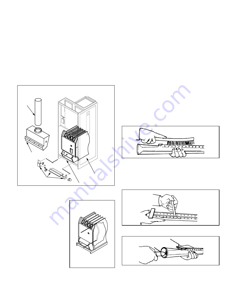
5 – Remove flue pipe and draft hood (figure 17).
HEAT
EXCHANGER
BURNER BOX
DAMPER ASSEMBLY
FIGURE 17
FLUE
PIPE
DRAFT HOOD
BURNER BOX COVER
FLUE PIPE, DRAFT HOOD AND BURNER BOX
DAMPER REMOVAL
6 – Remove flue restrictor over flue outlet (50E only).
7 – Gas manifold, gas valve
and burners do not
need to be removed and
can be left in place.
8 – Insert a 2 ft. steel rod
with a 20 in. length of
chain attached to one
end into top opening of
heat exchanger. Refer to
figure 18.
9 – Shake rod to drop chain
through clamshell into
burner cavity in bottom
of heat exchanger.
10 – Attach bottom of chain to 2 ft. (600 mm) rod.
11 – Push and pull the rods back and forth and up and
down with a vigorous motion. The chain will dis-
lodge the soot and scale deposits inside the heat ex-
changer. Repeat for each clamshell.
12 – With a shop vacuum or rags, clean out soot and
scale deposits from bottom of heat exchanger.
To clean burners:
NOTE–FOR UNITS WITH FLAME RODS, remove
two springs and withdraw rods from back of burner.
Clean flame rods with wire brush. Continue with
items 13 through 15 below and reinstall flame rods
and springs.
13 – Disconnect gas piping.
14 – Remove screws holding gas manifold in place and
pull burners from heat exchanger.
15 – Clean top of burner ports with a wire brush. See fig-
ure 19.
CLEANING TOP
FIGURE 19
16 – Clean burner ports by inserting a cleaning tool
(made from a piece of sheet metal cut to fit the burn-
er ports) and work in and out of each port. See figure
20.
CLEANING PORTS
FIGURE 20
CLEANING INSIDE
FIGURE 21


