background image

507327-01

Page 28  of  34

Issue 1809

Demand

15

ON
OFF

CAI

35

1

Pre-Purge

Ignitor Warm-up

Blower

“On” Delay

Post

 Purge

5 SEC

80

Ignitor

Gas Valve

Indoor Blower

39

Trial for

Ignition

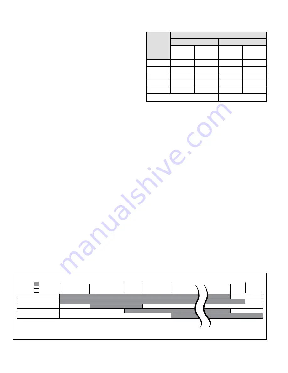
Blower on time will be 45 seconds after gas valve is energized. Blower off time will depend on “OFF TIME” Setting.

Figure 28. Integrated Ignition Control

5. 

Is the filter dirty or plugged? Dirty or plugged filters will 

cause the limit control to shut the unit off.

6.  Is gas turned on at the meter?
7.  Is the manual main shut-off valve open?
8.  Is the internal manual shut-off valve open?
9.  Is the unit ignition system in lock out? If the unit locks 

out again, call the service technician to inspect the unit 

for blockages.

10. 

Is pressure switch closed? Obstructed flue will cause 

unit  to  shut  off  at  pressure  switch.  Check  flue  and 

outlet for blockages.

11. 

Are  flame  rollout  switches  tripped?  If  flame  rollout 

switches are tripped, call the service technician for 

inspection.

Heating Sequence of Operation

See Figure 28

1.  When thermostat calls for heat, combustion air blower 

starts.

2.  Combustion air pressure switch proves blower 

operation. Switch is factory set and requires no 

adjustment.

3.  After a 15 second pre-purge, the hot surface ignitor 

energizes.

4.  After a 20 second ignitor warm-up period, the gas 

valve solenoid opens. A 4 second trial for ignition 

period begins.

5. 

Gas is ignited, flame sensor proves the flame, and the 

combustion process continues.

6. 

If  flame  is  not  detected  after  first  ignition  trial,  the 

ignition control will repeat steps 3 and 4 four more 

times before locking out the gas valve. The ignition 

control will then automatically repeat steps 1 through 

6 after 60 minutes.

7.  To interrupt the 60 minute, move thermostat from 

“Heat” to “OFF” then back to “Heat.” Heating sequence 

then restarts at step 1.

Gas Pressure Adjustment 

Gas Flow (Approximate)

Table 11. Gas Meter Clocking Chart

Capacity

Seconds for One Revolution

Natural

LP

1 cu ft

Dial

2 cu ft

Dial

1 cu ft

Dial

2 cu ft

Dial

-045

80

160

200

400

-070

55

110

136

272

-090

41

82

102

204

-110

33

66

82

164

-135

27

54

68

136

Natural - 1000 btu/cu ft.

LP-2500 btu/cu ft

Furnace should operate at least 5 minutes before checking 

gas flow. Determine time in seconds for two revolutions of 

gas through the meter. (Two revolutions assures a more 

accurate time.) Divide by two and compare to time in Table 

11. If manifold pressure matches Table 13 and rate is 

incorrect, check gas orifices for proper size and restriction. 

Remove temporary gas meter if installed.

NOTE

To obtain an accurate reading, shut off all other gas 

appliances connected to meter.

Supply Pressure Measurement

A threaded plug on the inlet side of the gas valve provides 

access to the supply pressure tap. Remove the threaded 

plug, install a field provided barbed fitting and connect a 

manometer to measure supply pressure. See Table 13 

for proper line pressure. Replace the threaded plug after 

measurements have been taken.

Summary of Contents for Allied Air 80G1DF

Page 1: ...Furnace Downflow Air Discharge This is a safety alert symbol and should never be ignored When you see this symbol on labels or in manuals be alert to the potential for personal injury or death Improper installation adjustment alteration service or maintenance can cause property damage personal injury or loss of life Installation and service must be performed by a licensed professional installer or...

Page 2: ...sions Model Number A B C D A80DF 80G1DF in mm in mm in mm in mm 045 08 14 1 2 368 13 3 8 340 13 330 4 3 4 121 045 12 070 08 070 12 090 12 17 1 2 446 16 3 8 416 16 406 6 1 4 159 090 16 110 12 21 533 19 7 8 504 19 1 2 495 8 203 110 16 110 20 135 20 24 1 2 622 23 3 8 546 23 584 9 3 4 248 ...

Page 3: ...ssue 1809 Figure 1 BLOWER ASSEMBLY CABINET CONTROL BOX INTERNAL FLUE PIPE ASSEMBLY FLUE CHASE HEAT EXCHANGER GAS VALVE ACCESS PANEL BURNER BOX ASSEMBLY COMBUSTION AIR INDUCER ROLLOUT LOCATED INSIDE BURNER BOX Parts Arrangement ...

Page 4: ...according to the current National Fuel Gas Code ANSI Z223 1 The National Fuel Gas Code is available from the following address American National Standards Institute Inc 11 West 42nd Street New York NY 10036 Clearances Adequate clearance must be made around the air openings into the vestibule area In order to ensure proper unit operation combustion and ventilation air supply must be provided accord...

Page 5: ...obile homes recreational vehicles or outdoors Use of Furnace as a Construction Heater These units are not recommended for construction heating during any phase of construction Very low return air temperature harmful vapors and operation of the unit with clogged or misplaced filters will damage the unit These units may be used for heating of buildings or structures under construction if the followi...

Page 6: ... and fireplaces force additional air that could be used for combustion out of the house Unless outside air is brought into the house for combustion negative pressure outside pressure is greater than inside pressure will build to the point that a downdraft can occur in the furnace vent pipe or chimney As a result combustion gases enter the living space creating a potentially dangerous situation In ...

Page 7: ...ntaining the furnace the return air must be handled by ducts which are sealed to the furnace casing and which terminate outside the space containing the furnace This is especially important when the furnace is mounted on a platform in a confined space such as a closet or small equipment room Even a small leak around the base of the unit at the platform or at the return air duct connection can caus...

Page 8: ...ngs shall each have a free area of at least one square inch per 4 000 Btu 645 mm per 1 17 kW per hour of the total input rating of all equipment in the enclosure Inlet Air from Crawlspace Outlet Air to Ventilated Attic NOTE The inlet and outlet air openings shall each have a free area of at least one square inch per 4 000 Btu 645 mm per 1 17 kW per hour of the total input rating of all equipment i...

Page 9: ...mmet used with a flexible mounting leg The bolt and washer must be removed before the furnace is placed into operation After the bolt and washer have been removed the rigid leg will not touch the blower housing Figure 7 Units with 1 2 HP Blower Motor Downflow Applications Allow for clearances to combustible materials as indicated on the unit nameplate Minimum clearances for closet or alcove instal...

Page 10: ...ensate trap and vent pipe installation The furnace may be installed on a combustible wood floor if an optional additive base is installed between the furnace and the combustible floor Installation on Non Combustible Flooring See Figure 11 1 Cut floor opening keeping in mind clearances listed on unit rating plate Also keep in mind gas supply connections electrical supply flue and air intake connect...

Page 11: ...abinet See Figure 13 NOTE Downflow combustible flooring kit is not used 1 Refer to reverse flow coil installation instructions for correctly sized opening in floor and installation of cabinet 2 When cooling cabinet is in place set and secure the furnace according to the instructions that are provided with the cooling coil Secure the furnace to the cabinet 3 Seal the cabinet and check for air leaks...

Page 12: ...rse flow of the flue gas may result in incomplete combustion and the formation of carbon monoxide gas This toxic gas might then be distributed throughout the house by the furnace duct system Venting A 4 inch diameter flue transition is factory installed on the combustion air inducer outlet of all models These series units are classified as fan assisted Category I furnaces when vertically vented ac...

Page 13: ...ered to be an exterior chimney An exterior masonry chimney that is not tile lined must be lined with B 1 vent or a listed insulated flexible metal vent An exterior tile lined chimney that is sealed and capped may be lined with a listed uninsulated flexible metal vent If the existing chimney will not accommodate a listed metal liner either the chimney must be rebuilt to accommodate one of these lin...

Page 14: ...e provided venting tables 3 The minimum vent capacity determined by the sizing tables must be less than the low fire input rating and the maximum vent capacity must be greater than the high fire input rating 4 Single appliance vents If the vertical vent or tile lined chimney has a larger diameter or flow area than the vent connector use the vertical vent diameter to determine the minimum vent capa...

Page 15: ...ust be resized Removal of the Furnace from Common Vent In the event that an existing furnace is removed from a venting system commonly run with separate gas appliances the venting system is likely to be too large to properly vent the remaining attached appliances Conduct the following test while each appliance is operating and the other appliances which are not operating remain connected to the co...

Page 16: ... 15 136 20 226 22 339 5 22 65 30 130 39 219 49 330 10 29 59 40 121 51 206 64 315 15 35 53 48 112 61 195 75 301 20 0 0 97 0 202 0 349 0 540 2 10 75 14 149 18 250 20 377 5 21 71 29 143 38 242 47 367 10 28 64 38 133 50 229 62 351 15 34 58 46 124 59 217 73 337 20 48 52 55 116 69 206 84 322 30 0 0 100 0 213 0 374 0 587 2 9 81 13 166 14 283 18 432 5 21 77 28 160 36 275 45 421 10 27 70 37 150 48 262 59 4...

Page 17: ...8 69 57 136 80 225 115 337 5 51 63 75 128 102 216 144 326 10 NR NR 95 116 128 201 182 308 15 NR NR NR NR 158 186 220 290 20 0 35 96 54 200 78 346 114 537 2 37 74 56 148 78 248 113 375 5 50 68 73 140 100 239 141 363 10 NR NR 93 129 125 223 177 344 15 NR NR NR NR 155 208 216 325 20 NR NR NR NR 186 192 254 306 30 0 34 99 53 211 76 372 110 584 2 37 80 55 164 76 281 109 429 5 49 74 72 157 98 271 136 41...

Page 18: ...92 52 146 69 220 15 1 21 50 33 89 47 142 64 220 2 22 53 35 96 49 153 66 235 3 24 55 36 102 51 163 68 248 20 1 21 54 33 99 46 157 62 246 2 22 57 34 105 48 167 64 259 3 23 60 35 110 50 176 66 271 30 1 20 62 31 113 45 181 60 288 2 21 64 33 118 47 190 62 299 3 22 66 34 123 48 198 64 309 Common Vent Capacity Type B Double Wall Vents with Type B Double Wall Connectors Serving Two or More Category I Appl...

Page 19: ... 60 77 110 112 175 169 278 2 51 62 81 115 117 185 177 290 3 54 64 85 119 122 193 185 300 NOTE Single appliance venting configurations with zero lateral lengths are assumed to have no elbows in the vent system For all other vent configurations the vent system is assumed to have two 90 elbows For each additional 90 elbow or equivalent for example two 45 elbows equal one 90 elbow beyond two the maxim...

Page 20: ...equire the installation of a manual main shut off valve and union furnished by the installer external to the unit The union must be of the ground joint type Compounds used on threaded joints of gas piping must be resistant to the actions of liquified petroleum gases IMPORTANT NOTE If emergency shutoff is necessary shut off the main manual gas valve and disconnect main power to the furnace The inst...

Page 21: ... 8 07 260 7 36 240 6 80 220 6 23 205 5 80 195 5 52 1 1 4 31 75 1 380 35 052 1400 39 64 950 26 90 770 21 80 660 18 69 580 16 42 530 15 01 490 13 87 460 13 03 430 12 18 400 11 33 1 1 2 38 1 1 610 40 894 2100 59 46 1460 41 34 1180 33 41 990 28 03 900 25 48 810 22 94 750 21 24 690 19 54 650 18 41 620 17 56 2 50 8 2 067 52 502 3950 111 85 2750 77 87 2200 62 30 1900 53 80 1680 47 57 1520 43 04 1400 39 6...

Page 22: ...ematic wiring diagram and troubleshooting and Figure 25 for field wiring The power supply wiring must meet Class I restrictions Protected by either a fuse or circuit breaker select circuit protection and wire size according to unit nameplate NOTE Unit nameplate states maximum current draw Maximum over current protection allowed is 15 AMP Holes are on both sides of the furnace cabinet to facilitate...

Page 23: ...elay Generator Use Voltage Requirements The following requirements must be kept in mind when specifying a generator for use with this equipment The furnace requires 120 volts 10 Range 108 volts to 132 volts The furnace operates at 60 Hz 5 Range 57 Hz to 63 Hz The furnace integrated control requires both polarity and proper ground Both polarity and proper grounding should be checked before attempti...

Page 24: ...507327 01 Page 24 of 34 Issue 1809 Figure 24 Wiring Diagrams ...

Page 25: ...BLOWER MOTOR B3 OUTDOOR UNIT C R G Y W Y G R C W Y C R ON OFF B6 3 5 BURNERS IGNITOR FLAME SENSOR S47 FLAME ROLLOUT SWITCH S47 FLAME ROLLOUT SWITCH R33 J159 P159 3 Field supplied ACC Wire 5 S145 is used with Honeywell gas valve when applied in LP gas units Use Copper Conductors ONLY WARNING Electric shock hazard Can cause injury or death Unit must be grounded in accordance with national and local ...

Page 26: ...TRALS RED GREEN W C R Y G C 2 3 4 1 1 2 3 4 5 6 7 8 9 10 11 12 3 AMP 32 VAC FUSE Terminal Designations HUM Humidifier 120 VAC LINE Input 120 VAC XFMR Transformer 120 VAC EAC Electronic Air Cleaner 120 VAC COOL Blower Cooling Speed 120 VAC HEAT Blower Heating Speed 120 VAC PARK Dead terminals to park alternate speed taps FLAME Flame sensor NEUTRALS Neutral terminals 120 VAC ...

Page 27: ...using property damage personal injury or death WARNING Gas Valve Operation See Figure 27 1 STOP Read the safety information at the beginning of this section 2 Set the thermostat to the lowest setting 3 Turn off all electrical power to the unit 4 This furnace is equipped with an ignition device which automatically lights the burners Do not try to light the burners by hand 5 Remove the upper access ...

Page 28: ...d flame sensor proves the flame and the combustion process continues 6 If flame is not detected after first ignition trial the ignition control will repeat steps 3 and 4 four more times before locking out the gas valve The ignition control will then automatically repeat steps 1 through 6 after 60 minutes 7 To interrupt the 60 minute move thermostat from Heat to OFF then back to Heat Heating sequen...

Page 29: ... set and require no adjustment Flame Rollout Switches This manually reset switches are located on the front of the burner box Pressure Switch The pressure switch is located in the heating compartment adjacent to the combustion air inducer The switch checks for proper combustion air inducer operation before allowing ignition trial The switch is factory set and requires no adjustment Temperature Ris...

Page 30: ...0 0625 3 5 No Change 0 0625 3 3 51W01 0 0550 3 5 LP Propane 11 0 13 0 11K50 0 034 10 0 11K50 0 034 10 0 11K50 0 034 10 0 11K45 0 032 10 0 090 Nat 4 5 10 0 No Change 0 0625 3 5 No Change 0 0625 3 5 No Change 0 0625 3 3 51W01 0 0550 3 5 LP Propane 11 0 13 0 11K50 0 034 10 0 11K50 0 034 10 0 11K50 0 034 10 0 11K45 0 032 10 0 110 Nat 4 5 10 0 No Change 0 0625 3 5 No Change 0 0625 3 5 No Change 0 0625 ...

Page 31: ...will break and remake thermostat demand to the furnace and automatically reset the integrated control to begin the ignition sequence Service ELECTRICAL SHOCK FIRE OR EXPLOSION HAZARD Failure to follow safety warnings exactly could result in dangerous operation serious injury death or property damage Improper servicing could result in dangerous operation serious injury death or property damage Befo...

Page 32: ...er manifold assembly to the vestibule panel and remove the assembly from the unit 7 Remove screws securing burner box and remove burner box 8 NOx units only Remove screw securing NOx insert Remove NOx insert See Figure 31 9 Remove screws from both sides top and bottom of vestibule panel 10 Remove heat exchanger It may be necessary to spread cabinet side to allow more room If so remove five screws ...

Page 33: ... other sources of ignition to check for gas leaks CAUTION 24 If a leak is detected shut gas and electricity off and repair leak 25 Repeat steps 24 and 26 until no leaks are detected 26 Replace access panel Planned Service The following items should be checked during an annual inspection Power to the unit must be shut off for the service technician s safety Fresh air grilles and louvers on the unit...

Page 34: ...sional installer or equivalent service agency or gas supplier Cabinet Parts Upper access panel Blower panel Top cap Control Panel Parts Transformer Integrated control Door interlock switch Circuit breaker Blower Parts Blower wheel Blower housing Motor Motor mounting frame Motor capacitor Blower housing cutoff plate Heating Parts Flame sensor Heat exchanger assembly Gas manifold Combustion air indu...

Reviews: