

• 10 •
3x1 mm²
5x1 mm²
Installation, Operation and Maintenance Manual /
ARIA2-IOM-1910-E
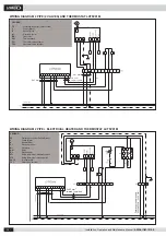
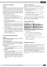
WIRING DIAGRAM 4 PIPE (2 VALVES) AND THERMOSTAT LXTFZ01M
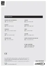
WIRING DIAGRAM 2 PIPE + ELECTRICAL HEATER AND THERMOSTAT LXTFZ01M
Permanent power supply
230V
ac/50Hz - 3x2,5 mm
2
2x0,5 mm²
twisted / shielded
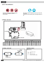
LEGEND
PE
. . . . . . . . Protective conductor (Yellow/Green)
L
. . . . . . . . . Phase (Black)
N
. . . . . . . . . Neutral (Blue)
A1
. . . . . . . . Electronic control
M1
. . . . . . . . Fan motor
XA1
. . . . . . . Terminal board
YV1
. . . . . . . Cool water valve actuator
YV2
. . . . . . . Heat water valve actuator
LEGEND
PE
. . . . . . . . Protective conductor (Yellow/Green)
L
. . . . . . . . . Phase (Black)
N
. . . . . . . . . Neutral (Blue)
A1
. . . . . . . . Electronic control
M1
. . . . . . . . Fan motor
KA1
. . . . . . . Relay
R1
. . . . . . . . Electric heater
ST1
. . . . . . . Safety thermostat - automatic switch
ST2
. . . . . . . Safety thermostat - manual switch
XA1-2
. . . . . Terminal board
YV1
. . . . . . . Water valve actuator
2x0,5 mm
2
twisted / shielded