05November2020/V1.0
Page 21/33
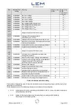
Note 1):
Setting of the baud rate of the data interface
The setting of the baud rate of the data interface with the above OBIS code must be performed with
one of the following parameters:
00
= 300 Baud
01
= 600 Baud
02
= 1200 Baud
03
= 2400 Baud
04
= 4800 Baud
05
= 9600 Baud
Note 2):
Set the device clock
The setting of the device clock with the above OBIS code must be performed with the following
parameter:
YYMMDDHHMMSS wwnz
YY
= year (00 .. 99)
MM
= month (01 ..12)
DD
=
day (01 .. 31)
hh
= hour (00 .. 23)
mm
= minute (00 .. 59)
ss
= second (00 59)
ww
= 00 (value is ignored when writing): week in the year
n
= 0 (value is ignored when writing): day in the week
z
= season flag (0 = winter time, 1 = summer time, 2 = UTC time)
The will code all timestamps (in the load profile and the log etc.) with UTC time.
Setting of the clock causes the capture period to end prematurely. The capture period which follows is
ended synchronously and is shortened as necessary if the adjustment is not made synchronously with
the capture period split.
If the time deviation between the old and the new device time is less than ±2 s, the clock is only
synchronised. The capture period is not completed in this case.
Please note that for the standard version of the the device clock is synchronised
automatically based on the time information included in the GPS data telegrams.
Note 3):
Consumption Point-ID
This dedicated register for the consumption point ID is an ASCII text string with 32 characters
maximum, as the definition of CPID has evolved: please refer to EN 50463-1:2017, § 4.2.5.2
Note 4):
Reading of transformer ratios
The configured transformer ratios of the for the four input channels yield from the primary
and secondary rated values identified by OBIS codes 0-223:110.112.118*# and 0-223:110.115.118*#
(#=0
→
channel 1, … ‚ #=3
→
channel 4).
Note 5):
Power values in the case of regenerated energy
In the case of negative power values (i.e. feeding regenerated energy to the supply system), the
power values given by the are marked with a negative sign.
Nevertheless, the OBIS code system originally distinguishes between separate registers for positive
and negative power values, the usage of only one value allows it easily to monitor the power directly
even in the case of alternating signs of the power value.


