background image

Field

Option

Description


Sun &

reflections

To increase the instrument measuring ability

during incident solar radiation and reflec-

tions, for example safety vests. This mode

has a considerable influence on the range

(restriction 100 - 150 m). This mode is auto-

matically deactivated when the instrument is

turned off.

Use ultra

fine aiming

Check box

Reduces the field of view of the ATRplus. The

setting is only applied for 

Aim at target

:

Automatic

.

Automati-

cally meas-

ure points

Check box

Check this box to survey the target points

automatically. The instrument turns automat-

ically and measures the target point. For

instruments with automatic aiming.

Next step
Page

 changes to the 

Report sheet

 page.Refer to "36 Apps - General".

49.2.3

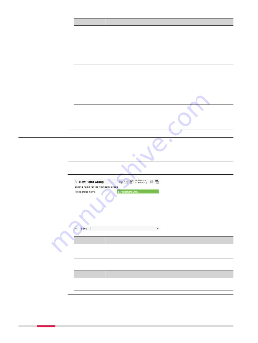
Creating New Point Groups

The points to be used for Sets of Angles can be selected and the first set

measured. The measurement settings of the first measurement to each point

are used for all further sets.

Highlight 

Create a new group

 in 

Measure sets of angles

 and 

OK

.

Key

Description

Store

To store the new points group.

Fn


Settings

To configure the Sets of Angles app.

Description of fields

Field

Option

Description

Point group

name

Editable field

The name of the points group.

Description

Access

New Point Group

854

Sets of Angles - TS

Summary of Contents for Captivate

Page 1: ...Leica Captivate Technical Reference Manual Version 3 0 English...

Page 2: ...ms after such changes is limited and lies rather in the responsibility of the user or the user s IT department Changes allowed Changes that might cause issues Installing software Loading another non L...

Page 3: ...verview of the product together with technical data and safety directions Intended as a quick reference guide GS10 GS15 Quick Guide GS14 GS16 Quick Guide GS18 Quick Guide GS25 Quick Guide TS16 Quick G...

Page 4: ...ZED RESELLER THIS TECHNOLOGY MAY CAUSE YOUR COMPUTER OR DEVICE TO AUTOMATICALLY CONNECT TO THE INTERNET ADDITIONALLY ONCE CONNECTED THE SOFTWARE MAY TRANSMIT YOUR SERIAL NUMBER LICENSE NUMBER TO LEICA...

Page 5: ...by Licensor may contain a special program that regulates and monitors the number of simulta neous users of the Software in a network environment together with the num ber of the licensed copies of the...

Page 6: ...applicable evaluation period or limited term or if Licensee undertakes certain other actions that may offset the security mode This Software may cause the Specified Computer Facility to automatically...

Page 7: ...ance with the periods for notify ing defects Licensee will not carry out modifications or repairs itself or permit such modifications or repairs to be carried out by unauthorized third parties If requ...

Page 8: ...eement In the event that Licensee faces legal proceedings based on the allegation that Licensee s use of a valid unmodified version of the Software in accord ance with the terms and conditions of this...

Page 9: ...of other Assurances Licensee hereby agrees that no verbal or written assurances declarations statements recommendations or advertising messages have been made by Licensor its employees sales partners...

Page 10: ...on in economic impact and intent This agreement may only be modified in writing signed by an authorized officer of Leica Geosystems This is the entire agreement between Leica Geosystems and Licensee r...

Page 11: ...Drag the supplied stylus from the left to the right To accept data entered into an edita ble field and exit the edit mode Tap on the screen outside of the editable field To open a context sensitive me...

Page 12: ...the job search Switches between the first and second level of function keys Enter Leaves the job search ON OFF Turns to Power Options menu when held for 2 s Favourites Without function The search fie...

Page 13: ...me It is possible that a function assigned to a hot key cannot be used in certain situations This step by step description shows how to assign the Regional panel to the F7 key 1 Select Leica Captivate...

Page 14: ...anel is an example of what a My GS Favourites or My TS Favourites menu can look like The functions which are assigned to the indi vidual places in the menu can differ depending on the settings Tap on...

Page 15: ...the internal memory Software maintenance is close to due date or has expired The reminder message has previously been confirmed with OK The icon will disappear when licence keys are entered manually o...

Page 16: ...delete a job move the job in the centre of the job carousel Press the key on the keyboard Apps carou sel Settings To access settings regarding the instrument instrument connections the software and th...

Page 17: ...ption OK To accept the settings and to return to the previous panel New To create a new job Edit To edit the highlighted job Delete To delete the highlighted job Data To view edit and delete points li...

Page 18: ...escription OK To select the highlighted option and to continue with the subsequent panel Fn Instru ment To switch between GS and TS mode Next step Connections Refer to chapter 18 Connections All other...

Page 19: ...to see the slope distance f Connections g Battery h Time 008292_001 a b c d e f g h a GS Position b Satellite Tracking c RTK Data Link d 2D position quality tap to see the antenna height e 1D positio...

Page 20: ...field of view and follows this prism Searching for the prism using Auto aiming Searching for the prism using PowerSearch Caution Connection between CS and TS is not established Displays the selected m...

Page 21: ...Measure distance Repeatedly average Measure distance Greater than 4km Measure distance 4km average Measure distance Highest precision on TS60 Leica round prism Leica 360 prism Leica mini prism Leica...

Page 22: ...ion Leica mini 360 Leica Machine Automation power prism MPR122 Leica reflective tape or HDS target Any surface User defined prism Distance measurement active Red laser is turned on Red laser is turned...

Page 23: ...where practical operation can commence Icon Description Navigation position available Navigation position available Tilt compensation active When the tilt pole initialisation is lost move the pole nat...

Page 24: ...urrent almanac Icon Description The number of visible satellites Displays the status of the real time device configured to be used Icon Description An arrow pointing down indicates a real time rover T...

Page 25: ...d in to Leica Exchange Data upload in progress Data download in progress Exchanging new data Data transfer problem Active Assist is active Leica technical support can gain remote access to the instrum...

Page 26: ...Icon Description Power level is getting low Power level is getting very low Battery empty Instrument turns off immediately 26 Icons...

Page 27: ...ionality related to the icon which was tapped Tap a bubble icon to use the functionality To close an icon pop up bubble Press any key on the keypad Touch the panel anywhere outside of the icon pop up...

Page 28: ...board arrow keys Information related to the cur rent setup on the instrument Hz and V Status Information Functionality Current horizontal and vertical angle Tap to see pole height Current horizontal a...

Page 29: ...position Tap to see pole height Tap to see 3D position quality Connections Status Information Functionality Internet online or not Status Bluetooth connection Start Leica Exchange Start Start Active...

Page 30: ...d Filter on Available when Filter learn was used before Turns on the PowerSearch filter and excludes the learned prisms from a PowerSearch Filter off Available when Filter learn was used before Turns...

Page 31: ...pm Description of fields Field Description Current setup ID The current setup Instrument height Instrument height of the current setup Setup method The setup method used for the current setup Easting...

Page 32: ...to Available when Hz angle display North azimuth is set in Regional Angle page V angle Editable field Vertical direction for the instrument to turn to Next step Page changes to the Relative page The...

Page 33: ...o start the telescope movement Press an arrow key again to speed up the movement Press any of the other arrow keys while the instrument turns to stop the movement Press OK to stop the instrument movem...

Page 34: ...ue to time required for data transfer and computation of position Depends on the use of the prediction mode Position quality and Height quality Available for phase fixed and code only solutions The 2D...

Page 35: ...ty Next step IF THEN the instrument is a GS18 and the tilt compensation is active Page changes to the Tilt page the instrument is not a GS18 or the tilt compensation on a GS18 is inac tive OK exits Cu...

Page 36: ...s angle is calculated by the GS18 Tilt quality The accuracy of the tilt angle of the antenna Direction of tilt The azimuth of the tilted antenna pole Direction of tilt quality The accuracy of the azim...

Page 37: ...ues of rover and base Health To view the numbers of satellites categorised in good bad and unavailable More To display information about the SNR values for sat ellites Page To change to another page o...

Page 38: ...0 elevation and the cut off angle is marked grey Key Description OK To return to the Leica Captivate Home menu GPS off GPS on To hide or show the GPS satellites shown by the prefix G GLO off GLO on T...

Page 39: ...the number of satellites tracked and the number of satellites available above the cut off elevation mask Key Description OK To return to the Leica Captivate Home menu Page To change to another page o...

Page 40: ...DBX points logged The number of points stored to the database Next step Page changes to the Point occupation page Description of fields Field Description Current dynamics Shows if the instrument is m...

Page 41: ...e used Name of page Description RTK base page Base is a real base station Base Nearest page Base is the closest to the rover determined by for example SmartNet Base i MAX page Base information is indi...

Page 42: ...l Radio Settings Refer to 19 3 Radios for GPS Real Time Start RTK stream To start streaming RTK data Stop RTK stream To stop streaming RTK data 5 7 2 RTK data link stat This panel shows information re...

Page 43: ...the current position solution Last data sent Available for RTK base Seconds since the last mes sage from the base was sent Last data received Available for Rover Satellite Tracking Seconds since the l...

Page 44: ...etwork selected in RTK Rover Settings Refer to RTK Rover Settings RTK network page Status The current mode of the digital cellular phone The options are Unknown Detection and Registered Bluetooth Avai...

Page 45: ...the type of base being used Name of page Description RTK base page Base is a real base station Base Nearest page Base is the closest to the rover determined by for example SmartNet Base i MAX page Ba...

Page 46: ...er of aux ref The number of active auxiliary base stations from which data is received Availability depends on selec ted network Antenna at base The antenna used at the base Sensor type at base The in...

Page 47: ...e GS The following provides additional information on the satellite data received using real time message Information of those satellites is displayed which are used on both base and rover Access Data...

Page 48: ...for L1 and L2 Code L1 Code L2 Code L5 The pseudorange from the antenna to the GPS satel lite for L1 L2 and L5 Code L1 Code L2 The pseudorange from the antenna to the GLONASS satellite on L1 and L2 GA...

Page 49: ...vice 4 Quote the equipment number shown on the panel to your supporter Leica technical support has now remote access to your TS instrument or field controller 5 Select End Active Assist to disconnect...

Page 50: ...external power Shows if an external power supply is connected If an external battery is connected the percentage of remaining power capacity is displayed numerically Applies also to wall plugs Interna...

Page 51: ...he jpg file is stored in the DBX JOB IMAGES folder of the data storage device The predefined templates are optimised for A4 printout User defined tem plates can be optimised for any format A screensho...

Page 52: ...storage device To make a user defined template selectable in the list transfer the template to the internal memory in Leica Captivate Home Set tings Tools Transfer user objects Refer to 29 1 Transfer...

Page 53: ...torage device or deleting all jobs Data is stored to a job After formatting the data storage device the default job is used until a user defined job is created and selected The properties of the job d...

Page 54: ...menu Display in job carousel Check box When this box is checked the job is visible in the job carousel When this box is not checked the job is invisible in the job carousel Exclude jobs from the job c...

Page 55: ...ption Store To store the settings Add To link a control job to the job Accesses Choose Linked Jobs Refer to Choose Linked Jobs Remove To delete the highlighted control job from the list of linked jobs...

Page 56: ...is stored If the working job and or linked jobs are moved to another device the link between both is remembered Source indicates that the source job of the data is not available in the expected data s...

Page 57: ...the Linked design data page The design data selected in this panel are local design data In the 3D viewer and when using the apps the global design data will be overwritten by linked design data from...

Page 58: ...ither typed in manually in the Alignment editor app or converted from a road design package The road job is a read only source of infor mation and cannot be selected as a job The selected Road design...

Page 59: ...ent setup above the reference datum Normally this is the height above mean sea level MSL Key Description Store To store the settings Page To change to another page on this panel Fn ppm 0 To set Geomet...

Page 60: ...scale from Projection height info and Compute scale from Current setup Geomet ric ppm Display only For Projection height info Geometric ppm Map projection ppm PPM height ppm value calculated fromGrou...

Page 61: ...ometric ppm value cannot be automatically calculated A message appears allowing the user to either manually enter the ppm values or accept ppm values of 0 All jobs on the available data storage device...

Page 62: ...he points and lines from the linked jobs are dis played Selected filters for the data set points are applied The Dataset panel can also be accesses by a hot key or a favourites keys 6 3 Choosing a Job...

Page 63: ...of when the job was created Last used Display only The date of when the job was last accessed Use a DTM Check box When this box is checked a DTM job can be selected A DTM job holds DTM Digital Ter ra...

Page 64: ...l job can be selected Rail design Selectable list Contains all the information about the rail design including the geometry of the centre line and the rail definition superelevation The files are stor...

Page 65: ...unnel jobs To view edit and delete points lines images and scans stored with the job Points lines images and scans are shown on separate pages Selected sort and filter settings apply For Road Rail or...

Page 66: ...new codelist to the job The name of this codelist is copied to the job Codes To view codes currently stored in the job Refer to 6 5 Man aging Job Codes Data To view edit and delete points and lines s...

Page 67: ...lete the highlighted control job from the list of linked jobs The corresponding points and lines will be removed from the data set Dataset To list all points and lines contained in the available and v...

Page 68: ...and or linked jobs are moved to another device the link between both is remembered Source indicates that the source job of the data is not available in the expected data storage device If the data st...

Page 69: ...To view edit and delete points and lines stored with the job Points and lines are sorted by time in one list Description of metadata Metadata Description The name of the CAD files that can be used Th...

Page 70: ...there are multiple layers the layer to display in 3D viewer can be selected Date cre ated Display only The date of when the job was created Use a road design Check box When this box is checked a road...

Page 71: ...line and the tunnel profile The files are stored in the DBX folder or a subfolder of DBX The tunnel job is a read only source of infor mation The selected Tunnel design is visible in 3D viewer Key Des...

Page 72: ...with up to four characters is added in front of the ID of the imported CAD points lines or areas Objects to create when importing entities Vertices and lines Imports the CAD lines into the job Create...

Page 73: ...y Description OK To return to New Job Linked jobs page Check box behaviour Description Checks or unchecks the check box of the highlighted job The behaviour depends on the current status of the check...

Page 74: ...s keys 6 5 Managing Job Codes To view edit group and sort all codes currently stored in the job 1 Select View edit job properties from the job menu in Leica Captivate Home 2 Page until the Codelist pa...

Page 75: ...le The differences are explained in the table Type of code Description Point codes New attributes can be added with New attrb For new jobs The line style line colour and string num ber can be changed...

Page 76: ...to select all points at once Key Description OK To close the panel and return to the panel from where this panel was accessed New To create a point Edit To edit the highlighted point In case of multi...

Page 77: ...or deselect all points at once Check box behaviour Action Description Checks or unchecks the check box of the highlighted point The behaviour depends on the current status of the check box Checks or u...

Page 78: ...ted Nav or Estimated Est Point measured within a Stake app Next step Page changes to the Lines page Key Description OK To close the panel and return to the panel from where this panel was accessed New...

Page 79: ...coming an area Next step Page until the 3D viewer page is active For information on camera and images refer to 32 4 Image Management Check one or multiple scans for a perspective display of the 3D poi...

Page 80: ...ID template or to change back to the next ID from the configured ID template Description of fields Field Option Description Point ID Editable field The name of the new point The configured point ID t...

Page 81: ...odelist are used All point codes of the job codelist can be selected The description of the code is shown as a display only field The attributes are shown as display only editable fields or selectable...

Page 82: ...r points with the same original name regardless of their class Points of Class Reference cannot be renamed Changing coordinates of a point which has been previously used in other apps for example COGO...

Page 83: ...tween the Design easting and the Measured easting Difference in northing Display only The difference between the Design north ing and the Measured northing Cut Fill Display only The height difference...

Page 84: ...ment has been taken in both faces More displays the horizontal angle or the azimuth from the point to the instru ment For TS points measured with Measure Foresight Listed are the setup ID the backsigh...

Page 85: ...nt Offset applied Updated if offset has been edited Height Display only The height measured at the stored point Offset applied Updated if offset has been edited Next step Page changes to the next page...

Page 86: ...d from the content of the data for mat Only RTCM v3 and Leica 4G are able to provide this number Mountpoint Display only The name of the correction data stream that was selected from the source table...

Page 87: ...7826 m 1 2154 m fill The displayed value is 1 2154 m Information Editable field Additional information that must be stored with the elevation Only the entered Information which also has an entered el...

Page 88: ...point can be recorded using the same point ID If the Duplicate points mode is activated an average is calculated when more than one measured coordinate triplet is available for the same point ID The a...

Page 89: ...ging with position only or height only points Position only points height only points and points with full coordinate triplets are handled in the averaging The Mean page can be accessed if When a poin...

Page 90: ...local coordinate sys tem is active Differences exceeding the defined limit are indicated by Description of metadata Metadata Description Use The use of a measured coordinate triplet in the averaging A...

Page 91: ...ob name Lines page press New Key Description Store To store the new line entered and all associated information Page To change to another page on this panel Fn Indiv ID or Fn Run For an individual nam...

Page 92: ...tion about the image size and the time and the date of when the image was stored Next step Page changes to another page on this panel To create lines with certain codes use quick coding The job codeli...

Page 93: ...tart time Display only The time date when the line was created An edited line retains the creation value for Start time End date and End time Display only The time date when the last point was added t...

Page 94: ...e type real or integer must be cre ated in Infinity Last Available if a code has been previously used in the job To select from a list of last used codes The codes are sorted by time with the most rec...

Page 95: ...In Job name General page press Fn Log All points lines and free codes stored within the job are displayed They are always sorted by time with the most recent record at the top For lines the value for...

Page 96: ...a and images refer to 32 4 Image Management The sort and filter settings are stored in the job They are remembered after turning off the instrument When a job becomes active then the sort and filter s...

Page 97: ...t point class only Shows points of highest class Range of point IDs Shows points with point IDs between the entered start and end ID The points are left aligned and sorted by the first digit Pt IDs ma...

Page 98: ...the last point to be displayed Control Ctrl Adjusted Adj Reference Ref Measured Meas Navigated Nav Estimated Est None Show or Hide Available for Filter to show Certain point classes only Defined class...

Page 99: ...ields Field Option Description Sort by Line ID ascending Line ID descending Start point oldest first Start point newest first End point old est first End point newest first Always available The method...

Page 100: ...Use To activate and deactivate the filter for the highlighted code None or All To deactivate or activate all point codes Fn Sort To define the order of the codes Accesses Sort Codes 7 6 3 Stakeout Fi...

Page 101: ...accessed Reset To reset the staked flag for all points of the currently job Description of fields Field Option Description View All points Shows all points Points to stake Shows points not yet staked...

Page 102: ...list s for a job Copy of codes Job Job codelist The creating editing and managing of codelists is explained in this chapter In order to use a codelist on the instrument it must be transferred from the...

Page 103: ...ist Codes To access Codes where codes can be created edited or deleted and code groups can be accessed Description of fields Field Option Description Name Editable field A unique name for the codelist...

Page 104: ...when editing a job The indicates codes which have attributes attached Key Description OK To close the panel and return to the panel from where this panel was accessed New To create a code Refer to 8...

Page 105: ...racter set the allowed length of the code name is short ened depending on the characters used Code description Editable field A detailed description of the code This description can be for example the...

Page 106: ...line is displayed Attribute field Editable field Up to 20 attributes can be created Attributes of attribute type manda tory or fixed and of value type real or integer must be created in Infin ity 8 5...

Page 107: ...e new code group typed in and returns to Code Groups Edit Available for codelists in the internal memory To edit the highlighted code group In Edit Code Group type in the changes for Name Store stores...

Page 108: ...d with a TS instrument are always stored in local grid coordinates regardless of the coordinate system being used One coordinate system can be attached to a job at one time This coordinate system rema...

Page 109: ...er of control points used for the determination and the date of when the coordinate system was created Fn Set deflt To turn the highlighted coordinate system into a user defined default coordinate sys...

Page 110: ...ontrol points The method by which residuals are distributed throughout the transformation area The transformation results become more real istic and any strain is dispersed in the transformation 1 dis...

Page 111: ...coordinate system 2 Press New or Edit 3 Highlight Transformation 4 ENTER to access Transformations Listed are all Classic 3D transformations stored in the database DBX Any unavailable information is s...

Page 112: ...e for the new transformation The name can be up to 16 characters long and include spaces Type Display only No other transformations than Classic 3D can be created Next step Page changes to the Paramet...

Page 113: ...are all ellipsoids stored in the database DBX Key Description OK To select the highlighted ellipsoid and to return to the previ ous panel New To create an ellipsoid Refer to 9 5 2 Creating Editing an...

Page 114: ...tening f 9 6 Projections 9 6 1 Accessing Projection Management Projections cannot be accessed for coordinate systems with source RTCM Refer to Automatic coordinate system RTCM transformation parameter...

Page 115: ...r Conformal projection onto a cylinder with its axis lying on the equatorial plane The cylinder is tangential to a meridian TMx A customised projection for use in the UK based on the UTM projection UT...

Page 116: ...of the centre of the projection RSO Rectified Skewed Orthomorphic This is a special type of Oblique Mercator projection 9 6 2 Creating Editing a Projection In Projections highlight a projection A copy...

Page 117: ...New or Edit 3 Highlight Geoid model 4 ENTER to access Geoid Models Listed are all geoid models stored in the database DBX Any unavailable infor mation is shown as For example would be shown if the ge...

Page 118: ...or each geoid field file on the data storage device or in the internal memory one geoid model is automatically created The names given to the geoid models are those names which were entered in Infinit...

Page 119: ...hts but no coordi nates in file Points are imported without coordinates but with local height and code if available Coordinates but no heights in file Points are imported without height but with coord...

Page 120: ...ates or heights in file No import MxGenio LandXML Terramodel Carlson Japan XML DTM data Format definition DXF file containing DTM data XML data Import variables Definable points lines coordinate sys t...

Page 121: ...ected To job Selectable list Available when Create new job on import is not checked Editable field Available when Create new job on import is checked The name of the new job Create new job on import C...

Page 122: ...ten header lines which can exist in an ASCII file to be skipped Select the number of header lines Delimiter Selectable list The separator between the import variables Point ID position Easting positi...

Page 123: ...ep 1 OK leads back to Import ASCII GSI Data 2 Fn Heights to access Define Ht Type Easting Description of fields Field Option Description Import as Selectable list The height type for the imported data...

Page 124: ...DE directory of the data storage device Import alignments Check box When the box is checked the job type Road Rail or Tunnel can be chosen A job name can be entered and a Road Rail or Tunnel job is cr...

Page 125: ...imported lines Units used within dxf file Selectable list Choosing the unit for the DXF data to be imported Objects to create when importing entities Vertices and lines Imports the CAD lines into the...

Page 126: ...enu select Import data DTM Key Description OK To import the data Fn Settings To define the linear units of the data to be imported Description of fields Field Option Description From device Selectable...

Page 127: ...ored in the DATA directory of the data storage device For Carlson At least one file in Carlson format with the file extension cl is stored in the DATA directory of the data storage device From the job...

Page 128: ...orage device can be selected Section file Selectable list For Data type to import Terramodel All ASCII cross section files with the extension txt in the DATA directory on the data stor age device can...

Page 129: ...tion is also possible in 3D viewer IF THEN a single line must be selected tap on the line multiple lines must be selected click the icons and Drag the stylus on the panel in a diagonal line to make a...

Page 130: ...Displays the name of all the lines Use as Displays a line selected as external chainage centreline track centreline left rail or right rail Next step OK start the import Key Description OK To start t...

Page 131: ...the Import metadata for excluding including the highlighted layer from to import Fn All or Fn None To change the setting for the Import metadata for all layers at once Description of metadata Metadat...

Page 132: ...Refer to the online help of Leica Geo Office or Leica Instrument Tools for information on creating format files Units Defined within the format file Coordinate con version All coordinate types are sup...

Page 133: ...ing the coordinate system Height If a geoid model exists then orthometric height is supported otherwise ellipsoidal height is exported Units Metre US Ft or Int Feet Gons Dec Deg DMS 11 2 Exporting Dat...

Page 134: ...e selected job is located Output file Editable field The name of the file to which the data is exported Next step Fn Settings accesses Settings Key Description OK To return to the previous panel Fn De...

Page 135: ...s To update the coordinate system in which the coordinates are exported Description of fields Field Option Description Job Selectable list To select the job to export Format file Selectable list The f...

Page 136: ...ttings To define what is exported Description of fields Field Option Description Job Selectable list To select the job to export To device Selectable list Available for To folder Data Defines which da...

Page 137: ...step Page changes to the DXF specific page For information on camera and images refer to 32 6 Exporting Images Description of fields Field Option Description Export lines closed lines Selectable list...

Page 138: ...ion of metadata Metadata Description The name of the label Export Shows if the label is exported or not Layer name The name of the layer that is exported which can be Name of a user defined layer If t...

Page 139: ...his block Layer name Selectable list Available for Layer name User defined is checked The name of the layer Export code descriptions Check box Available when Export Point Code labels is highlighted in...

Page 140: ...port The selectable list depends on the setting for Job type To device Selectable list Defines where the exported data are saved to To folder Selectable list The data can be exported to the DATA direc...

Page 141: ...es Check box When this box is checked the free code free code description free code group and the free code attributes are all exported to the LandXML file associated to each exported point Free code...

Page 142: ...m a LandXml file as they only read plan features in their field to finish routine Parcel objects are used in AutoCAD Civil 3D Parcels represent lots in a subdivision of real estates or features with c...

Page 143: ...checked and the correct password was typed in then this information read and displayed from the style sheet To device Selectable list Defines where the exported data is saved to To folder Selectable l...

Page 144: ...D to each position loca ted TDS RW5 file Point codes are used to generate raw linework in TDS Foresight MicroSurvey RW5 file Point codes are used to match the Description Keys in MicroSurvey CAD to ea...

Page 145: ...e setting panel Description of fields Field Option Description Use numeri cal point ID Check box Available unless Export format TDS RW5 Point ID off set Editable field Available when Use numerical poi...

Page 146: ...ort format TDS RAW and when Create feature code FC and attrib ute AT records is checked When this box is checked then the two first attributes are appended directly to the code and not written as Attr...

Page 147: ...d the Source is changed to Copied Point the point coordinate quality is retained the Date and Time is retained From the job menu select Export data scroll down and select Between jobs Key Description...

Page 148: ...The configured ID template for lines is used The ID can be changed in the following ways To start a new sequence of line IDs type over the line ID For an individual name independent of the ID template...

Page 149: ...int a distance an azimuth and the gradient of the line A new point is created at the end of the line Point brng dist height diff and Line from point bear ing dis tance height dif ference For lines pol...

Page 150: ...nd point of the line Grade Editable field The gradient of the line from the start point to the end point of the line Horizon tal dis tance Editable field The horizontal grid distance from the start po...

Page 151: ...line ID For an individual name independent of the ID template Fn Indiv ID Fn Run changes back to the next ID from the configured ID template Create line from these points Editable field Enter a list o...

Page 152: ...of the new line The configured ID template for lines is used Type over the line ID to change it Starting point ID Editable field The point ID of the line start point The con figured ID template for p...

Page 153: ...3 Continue as if creating a new polyline Refer to Create new polyline Several segments Creating Points and Lines 153...

Page 154: ...ttings and to continue to the next panel Key Description Back To return to the previous panel Next To confirm the settings and to continue to the next panel Next step Next changes to the next panel IF...

Page 155: ...ions on the panel This panel is displayed if NO Bluetooth connection has previously been config ured Move the focus using the arrow keys or the stylus to select a Bluetooth device Key Description Back...

Page 156: ...on Description Manufac turer Selectable list The brand of the instrument Model Selectable list The instrument model Connect using Cable Blue tooth Long range TS or External radio How the instrument is...

Page 157: ...6 7 or 8 Number of bits in a block of digital data Stop bit 1 or 2 Number of bits at the end of a block of digi tal data Flow control None or RTS CTS Activates hardware handshake When the instrument...

Page 158: ...nfirm the settings and to continue to the next panel Next step Follow the instructions on the panel This panel is displayed if the chosen instrument model has NO previous used Bluetooth ID already sto...

Page 159: ...o Other Total Stations for supported functions Before using any Leica Legacy or third party total station ensure that the fol lowing values are set on the TS Instrument Settings Leica Legacy total sta...

Page 160: ...ed Topcon total stations for example GTS800 and above set the communication values through Prog Ext Link Setting RS232 For non motorised instruments ensure that the total station is in the measure men...

Page 161: ...e total station go to Set tings Obs Condition Tilt crn No 4 Required cable TDS DB9 Data Cable 148 SCGTSSOKTOP Topcon Sokkia Third party total station Nikon 1 Total station ppm scale Atmospheric ppm 0...

Page 162: ...ck To return to the previous panel Next To confirm the settings and to continue to the next panel Next step Independent of the selection made Next changes to a panel where the con nection type must be...

Page 163: ...res settings in WinCE Next step Next changes to the next panel IF THEN connected using RadioHandle Next changes to the next panel The RadioHandle is detected automatically if it is plugged into the TS...

Page 164: ...the TCPS broadcasts can be changed Changing channels changes the frequency at which the TCPS operates This may be necessary to enable multiple pairs of TCPS to work simultaneously in the same area wi...

Page 165: ...ty None Even or Odd Error checksum at the end of a block of digi tal data Data bits 6 7 or 8 Number of bits in a block of digital data Stop bit 1 or 2 Number of bits at the end of a block of digi tal...

Page 166: ...Use Win dows for all other settings required While using the RTK Rover Wizard the CS35 must physically be connected to the GS Key Description Next To accept changes and to continue with the subsequen...

Page 167: ...Existing RTK Profile Select an existing RTK profile from the selectable list Listed are profiles that match the instrument in use Key Description Back To return to the previous panel Delete Pressing t...

Page 168: ...turn to the previous panel Delete Pressing this key deletes the RTK profile currently shown in the selectable list Next To accept changes and to continue with the subsequent panel within the wizard De...

Page 169: ...CS is used the Internet device can be connected to the CS 3 5G modem port Bluetooth mobile phone a TS16 MS60 TS60 is used the Internet device can be connected to a Blue tooth phone of type GSM UMTS L...

Page 170: ...the panel from where this panel was accessed Edit To configure the parameters related to the highlighted con nection Refer to the sections on each individual connection in this chapter Control Availab...

Page 171: ...For TS In Connection Settings highlight TS Internet Edit For CS35 Use Win8 to configure an Internet connection For TS with GS In Connection Settings TS connections page highlight TS Internet Edit In C...

Page 172: ...the connection function ality CS modem GS Port 1 For GS10 GS25 The physical port P1 on the box For GS15 The red LEMO port GS Port 2 For GS10 GS25 The physical port P2 on the box For GS15 The black LEM...

Page 173: ...ants to access the Internet using the device the same IP address identifies the instrument This behaviour is important if the instrument is used as a TCP IP server IP address Editable field Available...

Page 174: ...ervice where you registered Password Editable field Available when Use DynDNS is checked Type in the password provided by the DynDNS service where you registered Display password Check box When this b...

Page 175: ...N profile This means besides the APN user name and password you must also ask your ISP for a list of open ports These open ports can then be configured on the GS for the Base RTK 1 and Base RTK 2 inte...

Page 176: ...you if this port is open If not change your data stream setting to a different port 18 3 GS rover GS base To connect the field controller to the sensor antenna either on the base or on the rover side...

Page 177: ...ected Bluetooth device 18 4 ASCII input 18 4 1 Configuration of an ASCII Input Connection The ASCII Input connection receives ASCII messages from third party devices such as depth sounders barometers...

Page 178: ...ted for ASCII input Next step Page changes to the Annotation 1 Annotation 2 Annotation 3 Annota tion 4 page Description of fields Field Option Description Store ASCII data to this annotation Check box...

Page 179: ...iption OK To accept changes and return to the panel from where this panel was accessed Send To send the command to the device Description of fields Field Option Description Command Editable field A me...

Page 180: ...le Bluetooth devices If more than one Bluetooth device is found a list of available devices is provi ded Device To create select edit or delete a device Refer to 20 2 Accessing Devices Description of...

Page 181: ...a d1 d4 d3 d1 Device height height of hidden point measurement device above P0 d2 Slope distance d3 Device height height of P1 above P2 d4 Height difference between hidden point measurement device and...

Page 182: ...re this panel was accessed Search Available when CS Bluetooth 1 or CS Bluetooth 2 are selected To search for all available Bluetooth devices If more than one Bluetooth device is found a list of availa...

Page 183: ...es and the base to be used For RTK rover In Connection Settings GS connections page highlight RTK rover Edit The available fields and keys on this panel depend on the selected settings Key Description...

Page 184: ...The red LEMO port For GS25 The physical LEMO port P1 on the box GS Port 2 For GS10 The physical port P2 on the box For GS15 The black LEMO port For GS25 The physical LEMO port P2 on the box GS Port 3...

Page 185: ...formats used to broadcast data for third party instruments RTCM 18 19 v2 Message according to RTCM version 2 x Uncorrected carrier phase and pseudorange Message 3 is also generated Use for real time o...

Page 186: ...dinate differences between the master and its auxiliaries 1015 Ionospheric Correction Differences message 1016 Geometric Correction Differences message 1021 Helmert Abridged Molodensky transformation...

Page 187: ...ut Message types for universal real time GNSS operation decoding from RTCM v3 MSM The receiver can decode RTCM v3 MSM 1071 Compact GPS pseudo ranges MSM1 1072 Compact GPS phase ranges MSM2 1073 Compac...

Page 188: ...ull Galileo pseudo ranges and phase ranges plus CNR high resolution MSM6 1097 Full Galileo pseudo ranges phase ranges phase range rates and CNR high resolution MSM7 1121 Compact BeiDou pseudo ranges M...

Page 189: ...and RTCM 20 21 v2 The availability of the following options depends on the selection made for SBAS tracking on the Advanced page Automatic SBAS SBAS satellites are tracked and the SBAS service used i...

Page 190: ...nts are used as reference Antenna at base Selectable list The antenna used at the base If the real time data format contains information of the antenna certain corrections based on this information ar...

Page 191: ...st The rover sends its position using NMEA GGA message to SmartNet From this position SmartNet determines the reference in a ref erence network that is closest to the rover The corrections from that r...

Page 192: ...to be sent as part of the Leica proprietary NMEA message By default the serial number of the instrument is displayed Next step Page changes to the Advanced page Description of fields Field Option Des...

Page 193: ...This switch allows maximum productivity and minimal costs with real time applications 1 Set up a base 2 On the base attach a digital cellular phone to one port and a radio to another port 3 Configure...

Page 194: ...ication This functionality is possible when position coor dinates from a previous reference network application are still stored in the internal memory Here Available for GGA position to send Last or...

Page 195: ...s can be configured on the instrument For RTK base In Base Connection Settings highlight Base RTK 1 Edit Two real time devices can be attached to two different ports for example a radio and a digital...

Page 196: ...orts are extra remote ports GS radio Available for GS14 GS16 GS18 GS modem Available for GS14 GS16 Device Display only The device currently assigned to the selected port within the active working styl...

Page 197: ...ata From 0 1s to 60 0s Rates for the transmission of raw observa tions The default settings are suitable for standard applications They can be changed for special applications A check is performed for...

Page 198: ...ase station from which data is accepted must be typed in at the rover The allowed minimum and maximum values vary From 0 to 31 For Leica and CMR CMR From 0 to 1023 For any RTCM version 2 format From 0...

Page 199: ...standard related to the marine electronics industry NMEA messages have been accepted as the standard for sharing specific data information between companies since the late 1970s Refer to E NMEA Messa...

Page 200: ...2 For GS10 GS25 The physical port P2 on the box For GS15 The black LEMO port GS Port 3 For GS10 The physical port P3 on the box For GS15 GS25 The slot for a device GS Port 4 For GS25 The physical port...

Page 201: ...D is checked Appears at the beginning of each NMEA message Messages to be streamed local coor dinates will be compu ted using the coordi nate system on the GS sensor Display only The NMEA messages cur...

Page 202: ...output timing method Key Description OK To accept changes and return to the panel from where this panel was accessed Edit To configure how the currently highlighted message is out put Refer to paragr...

Page 203: ...ion of positions is changed to allow the specified rate of NMEA positions The panel update remains unchanged Point type Available for Send message On point stored Defines the type of points for which...

Page 204: ...to control the instrument through the remote port Documentation for OWI and LB2 is available on request from the Leica Geosystems representative a message log to be requested from a remote client via...

Page 205: ...he hardware connected to the chosen port 18 11 PPS output The PPS output is an optional interface requiring a special port PPS stands for Pulse Per Second It is a pulse that is output at a specified i...

Page 206: ...Polarity Negative edge and Positive edge Measure the time from the negative edge or the positive edge of the pulse Next step Page changes to the Notification page Key Description OK To accept changes...

Page 207: ...itions where the events took place can be interpolated in Infinity Events logged during real time operations can also be exported to an ASCII file using an appropriate format file Additionally a notif...

Page 208: ...accept all events The shortest recording time is 0 05 s Description Editable field Records up to four lines of data with the event record Use the description to differen tiate between the two event re...

Page 209: ...sage format Connect using GS Port 1 GS Port 2 GS Port 3 or GS Port 3 The ports on the GS25 which are used for the connection GS BT The Bluetooth ports on the GS25 used for the connection Device Displa...

Page 210: ...ns available depend on the selection for Model The availability of the other fields depends on the selection made here For CS35 use Windows to config ure the connection itself CTR20 expansion pack To...

Page 211: ...panel was accessed Search Available when CS Bluetooth 1 or CS Bluetooth 2 are selected To search for all available Bluetooth devices If more than one Bluetooth device is found a list of available dev...

Page 212: ...t PPM GSI data is transmitted in blocks Every block consists of several data words refer to the examples in the following table Every data word begins with a two character Word Index the WI code speci...

Page 213: ...10002 000000000PNC0056 21 002 0000000012802530 22 002 0000000005255000 110003 000000000PNC0057 21 002 0000000011222360 22 002 0000000005433800 110004 000000000PNC0058 21 002 0000000010573550 22 002 00...

Page 214: ...cks are allowed to carry more than one value for exam ple ppm mm This data is automatically transferred with the according sign before each single value WI11 WI21 WI22 WI31 WI51 WI81 WI82 WI83 WI87 16...

Page 215: ...ence identification header including talker identifica tion A Talker ID appears at the beginning of the header of each NMEA message Time UTC time of position hhmmss ss Northing The Northing coordinate...

Page 216: ...the Checksum field When information for a field is not available the position in the data string is empty 18 15 CS Connection The Remote connection allows the TS instrument to be steered remotely fro...

Page 217: ...most keys are locked Available are Measure Distance and Store Distance and Store have the same functionality as on the CS or as on the TS16 MS60 TS60 when it is independently controlled Level goes to...

Page 218: ...ked the GeoCOM mode is activated Connect using Cable For TS16 The RS232 port For MS60 TS60 The cable USB port Radio han dle Hotshoe connection for RadioHandle This port is on top of Communication side...

Page 219: ...least squares adjustment operations Technology Description CDMA Code Division Multiple Access is a high speed data transmis sion for effective and flexible use of available resources such as bandwidt...

Page 220: ...al cellular phone base station to be dialled Open the selectable list to access Dial up Connection List where new base stations can be created and existing base stations can be selected or edited Refe...

Page 221: ...s played in theDisplay PUK code field When this box is not checked dots are dis played in the Display PUK code filed Next step Page changes to the Advanced page Description of fields Field Option Desc...

Page 222: ...ection For RTK rover and TS In Connection Settings highlight a connection which has a digital cellular phone of CDMA technology attached Control For RTK base In Base Connection Settings highlight a co...

Page 223: ...as config ured in Dial up Connection List Protocol Display only The configured protocol of the digital cellular phone at the selected Dial up connection as configured in Dial up Connection List Next...

Page 224: ...rs of the base stations can be controlled Changing the base station to be dialled is of interest in two cases Case 1 Two real time base stations each equipped with a digital cellular phone are set up...

Page 225: ...edited Refer to 19 6 Configur ing the Stations to Dial Number Display only The number of the modem at the selected Dial up connection as configured in Dial up Connection List Protocol Display only Th...

Page 226: ...in RTK Base Settings RTK 1 RTK Base Settings RTK 2 Data rates page to a different ID for each base site when configuring the base real time connection By doing so the rover can recognise if the incom...

Page 227: ...is selected as Radio type Different protocols are selectable Example Pacific Crest or TrimTalk compatibility The radio must be active to accept the settings The radio need not be connected to a com pu...

Page 228: ...using a particular radio channel Key Description OK To select the highlighted base station and to continue with the subsequent panel Channel 1 and Channel 1 Available for scanning base stations with...

Page 229: ...atel radio when pressing Store More To change between Spacing kHz and Rx Freq MHz on a rover respectively Tx Freq MHz and also Tx Power mW on a base Description of metadata Metadata Description Channe...

Page 230: ...h has an Internet device attached Control For RTK base In Base Connection Settings highlight a connection which has an Inter net device attached Control Key Description OK To accept changes and return...

Page 231: ...rce to access NTRIP Source Table Highlight a mountpoint about which more information is required This infor mation helps to configure the instrument to use the selected mountpoint as a base Press Info...

Page 232: ...he previous panel 19 6 Configuring the Stations to Dial 19 6 1 Accessing Dial up Connection List Dial up Connection List allows new stations to be created provides a list of base stations that can be...

Page 233: ...hted station Description of metadata Metadata Description Listed are all available base stations Number Phone number of the station to dial 19 6 2 Creating Editing a Station to Dial In Dial up Connect...

Page 234: ...ntional phone networks ISDN v 110 or ISDN v 120 For GSM networks Use coordi nates Check box Check this box to type in the approximate coordinates of the base station 19 7 Configuring the Server to Con...

Page 235: ...e To return to the panel from where this panel was accessed Page To change to another page on this panel Description of fields Field Option Description Server name Editable field A unique name for the...

Page 236: ...rmation NTRIP pass word Editable field A password is required to receive data from the Ntrip Caster Contact the Ntrip adminis trator for information Display password Check box When this box is checked...

Page 237: ...he base is on 3 The rover digital cellular phone contacts the selected base of which the phone number was pre defined Refer to 20 3 Creating Editing a Device 4 One rover can dial in to the base digita...

Page 238: ...imultaneously 20 1 3 Modems To transmit NMEA messages To transmit real time data Example of use 1 The base is equipped with a modem 2 The rover is equipped with a digital cellular phone 3 Ensure that...

Page 239: ...the rover use the radio when within radio range of the base and the digital cellular phone when radio recep tion is not possible The internal devices of the GS14 GS16 cannot be used simultaneously 20...

Page 240: ...urement devices are directly transferred If the device is not connected measurement can be typed in manually to calculate the coordinates of a hidden point Example of use 1 An instrument must be a rov...

Page 241: ...l Identification Number Registration Some GPRS Internet devices are predefined Other GPRS capable devices can be used as long as they use AT commands Their settings must be defined by creating a new d...

Page 242: ...nternet and Bluetooth devices To list all devices or to hide devices which are not Internet or Bluetooth capa ble Fn Default To recall previously deleted default devices and to reset default devices t...

Page 243: ...le for CS modem Data bits 6 7 or 8 Number of bits in a block of digital data Unavailable for CS modem Stop bit 1 or 2 Number of bits at the end of a block of digi tal data Unavailable for CS modem Flo...

Page 244: ...lows the Initialisation 1 Initialisation 2 or the Dial string to continue onto a new line Initialisa tion 2 Editable field Initialisation sequence to initialise digital cel lular phone modem Dial Edit...

Page 245: ...ase station Field Option Description GPS Check box Defines if the instrument accepts the GPS L1 L2 and L5 signals when tracking satellites For L2 and L5 the multi frequency licence is required Glonass...

Page 246: ...L2C signals instead of L2P signals if available Automatic L2 signals which are flagged as unhealthy are not recorded or used for real time computa tions Satellite health Sets the satellite tracking b...

Page 247: ...page and to the BeiDou page where GLONASS satellites Galileo and BeiDou satel lites used in the survey can be configured 2 OK returns to Satellite Tracking 3 OK returns to Leica Captivate Home or Leic...

Page 248: ...to 300 0 sec Rate at which raw observations are logged Recommendations For static operations with long baselines and over long time Rate 15 0 sec or Rate 30 0 sec For base stations for post processed...

Page 249: ...app The settings made in the Setup page are only used inside the Setup app Any changes made to the Measure Target for example using icons or hotkeys while the Setup app is active only affect the Setu...

Page 250: ...epending on the setting for Measure distance single or continuous measurements are performed Unavailable for SmartStation Measure distance Once When a single measurement with high preci sion is requir...

Page 251: ...e integrated ATRplus which automatically adjust the settings for optimal performance Good If weather conditions are normal then select this mode Rain fog To increase the instrument measuring ability d...

Page 252: ...2 MPR122 Prism 28 1 mm 6 3 mm For Machine Control purposes only Open the selectable list for Target in Measure Target This panel shows information about the additive constant the target type and the c...

Page 253: ...ype of target to be defined Leica con stant Editable field The additive constant for the selected prism as stored in the software An additive constant of 0 0 mm has been defined for the Leica Geosyste...

Page 254: ...r Editable field A name of the creator or other comments can be entered 22 2 Target search The settings on this panel define the size of search windows for prisms to be searched in The prisms can be s...

Page 255: ...easured point If the target is lost when Aim at target With lock then the instrument turns back to the last stored point The field of view is disabled while the instrument is reposition ing Next step...

Page 256: ...cription OK To accept changes and return to Leica Captivate Home Page To change to another page on this panel Fn Default To recall the default settings Description of fields Field Option Description A...

Page 257: ...n OK To accept changes and return to Leica Captivate Home Page To change to another page on this panel Fn P E To change Pressure to Elevation above mean sea level and back Fn T To change Humidity to W...

Page 258: ...Check box If checked refraction correction is applied to measurements Coefficient k Editable field Refraction coefficient to be used for calcula tion Next step Page changes to another page 22 4 Level...

Page 259: ...nstru ment is turned off when the instrument is turned on again the compensator is activa ted Off The mode stays always deactivated The compensator is deactivated also after turning off and on the ins...

Page 260: ...the red laser of the reflectorless EDM is turned on Use the reticule light Check box If checked the reticle illumination is turned on Intensity From 0 to 100 To adjust the reticle illumination intensi...

Page 261: ...ca Captivate Home Set To define new search window Follow the instructions on the panel Show To position the telescope to corners of the search window Page To change to another page on this panel Descr...

Page 262: ...2 7 Check Adjust 22 7 1 Overview Leica Geosystems instruments are manufactured assembled and adjusted to the best possible quality Quick temperature changes shock or stress can cause deviations and de...

Page 263: ...anufacturing process the instrument errors are carefully deter mined and set to zero As mentioned above these errors can change and it is highly recommended to redetermine them in the following situat...

Page 264: ...small deviations of the current aiming 22 7 2 Details on Instrument Errors Instrument errors occur if the standing axis the tilting axis and the line of sight are not precisely perpendicular to each...

Page 265: ...oint to a target located significantly below or above the horizontal plane To avoid influences from the horizontal collimation error c the horizontal collimation has to be determined prior to the tilt...

Page 266: ...or of the instrument The longitudinal compensator index error l has a similar effect as the vertical index error and affects all vertical angle readings The transversal compensator index error t is si...

Page 267: ...xample focus position rotation scale and lens distortion The full calibration is performed after production and in service Instrument error Effects Hz Effects V Elimination with two face measurement A...

Page 268: ...get aiming or Check adjust the compensator index error line of sight error auto matic target aiming telescope camera and press Next The combined adjustment procedure determines the following instrumen...

Page 269: ...When this box is checked the determination of the telescope camera horizontal and verti cal zero point adjustment values is included In Cameras Overview camera page Use TS overview camera must be chec...

Page 270: ...get Description of fields Field Option Description Number of measure ments Display only Shows the number of runs One run consists of a measurement in face I and II All other fields Display only The st...

Page 271: ...alid on the instrument 22 7 5 Tilting Axis Adjustment a In Check Adjust What do you want to do select Check adjust the tilting axis and press Next This adjustment procedure determines the following in...

Page 272: ...o the other face 008372_001 180 180 3 Non motorised instruments guide to the other face using the Tele scope Positioning panel 4 Measure to measure the same target in the other face and to calcu late...

Page 273: ...or appended to an existing report sheet Redo To reject the result and to repeat the complete check and adjust procedure Description of fields Field Option Description New Display only The new determin...

Page 274: ...repeated All measurements of the current run are rejected and are not averaged with the results from previous runs Key Description Next To measure the target Description of fields Field Option Descrip...

Page 275: ...ion New Display only The new determined and averaged instru ment errors Old Display only The old instrument errors which are currently valid on the instrument 22 7 7 Viewing the Current Values In Chec...

Page 276: ...played each time the instrument is turned on The reminder helps to redetermine the instrument errors regularly Never A reminder message to readjust the instrument is never dis played This setting is n...

Page 277: ...Circular Level of the Prism Pole 1 Suspend a plumb line 1 2 4b 4a TS_080 2 Use a pole bipod to align the prism pole parallel to the plumb line 3 Check the position of the circular level on the prism p...

Page 278: ...paper 5 Mark the centre of the red dot on the ground 6 Turn the instrument through 360 slowly carefully observing the movement of the red laser dot The maximum diameter of the circular movement descri...

Page 279: ...nts must always be firm and tight 1 Tighten the leg cap screws moderately with the supplied allen key 2 Tighten the articulated joints on the tripod head enough to keep the tripod legs open when lifti...

Page 280: ...Check box Defines if the instrument accepts the GPS L1 L2 and L5 signals when tracking satellites For L2 and L5 the multi frequency licence is required Glonass Check box Defines if the instrument acc...

Page 281: ...Captivate Or use the Web server Defines if the instrument accepts L Band tracking to receive correction data coming from Terrastar satellites Terrastar is a GNSS augmentation service working with geo...

Page 282: ...rdinate system in use A PPP solution is independent from a refer ence station or network and therefore the link to the reference frame of the used coor dinate system is not given any more The coordina...

Page 283: ...es the L2C signals instead of L2P signals if available Automatic L2 signals which are flagged as unhealthy are not recorded or used for real time computa tions Satellite health Sets the satellite trac...

Page 284: ...nd a prefix C for BeiDou satel lites System OK N A or Unhealthy Information on the satellite health taken from the almanac N A stands for not availa ble User Bad Excludes satellite from tracking OK In...

Page 285: ...the use of apps The antenna height can still be changed during a survey The initial value depends on the selected antenna Unavailable for SmartStation The height is added in the Setup and Measure app...

Page 286: ...t antennas and to reset default antennas to the default settings User defined anten nas are not affected 23 2 3 Creating Editing an Antenna In Antennas highlight an antenna All offsets are copied from...

Page 287: ...ield The serial number of the antenna Setup num ber Editable field The setup number of the antenna Identifies the version number of the current calibra tion Next step Store stores the new antenna 23 3...

Page 288: ...e tilt compensation On is set in Tilt Compensation Store data on CS control ler or GS sensor Data can either be logged to the field con troller or to the GS For GS08plus data can only be logged to the...

Page 289: ...d occupy ing distinct points in kinematic chains Rate between 0 1 sec and 2 0 sec Logging starts when Selectable list Available for Store data on GS sensor Data logging can start as soon as the instru...

Page 290: ...tometer used Tilt compensation also works with Navigated and Code solutions High accuracy positions are recommended to speed up the tilt com pensation initialization Raw data logging is turned off whe...

Page 291: ...Field Option Description When this box is not checked the pole must be held vertically over the survey mark using the circular bubble on the pole Settings GS Sensor 291...

Page 292: ...ntenna types are supported IF the antenna is AND the accessories are AND the setup is THEN the measure ments required are Leica antenna for example GS15 standard Leica tripod or tri pod short vertical...

Page 293: ...e centre offsets of all Leica antennas were executed by Geo GmbH 24 2 Antenna Reference Planes ARP The Antenna Reference Plane is where the antenna heights are measured to is where the phase centre of...

Page 294: ...e height difference between the pillar bench mark and the Antenna Reference Plane of the antenna Normally it is deter mined indirectly by levelling Sometimes it is difficult to measure to the MRP dire...

Page 295: ...th GAD31 screw to stub adapter Tripod setup At the beginning of a survey enter the vertical height reading into the instrument The vertical offset of 0 00 m is stored in the antenna setup record for a...

Page 296: ...of the height hook It is determined using the height hook 1 Determine the vertical height reading using the height hook 2 For Leica standard antennas plus accessories the vertical offset is 0 36 m for...

Page 297: ...ical height reading is the height difference between the bottom end and the top end of the pole Usually this height difference is a fixed value At the beginning of a survey enter the vertical height r...

Page 298: ...tenna heights For a SmartStation setup the antenna height value in the Measure panel must equal the value for Instrument height Instrument height is seen in the preceding Choose Setup Point Leica stan...

Page 299: ...asured points which are all stored with the same point ID Don t check Averaging is turned off No other fields are available Method The method used for computing the aver age Available for When a point...

Page 300: ...el Description of fields Field Option Description Automati cally stop point meas urement Check box Activates a selectable list for the stop criteria Stops the measurements automatically when the param...

Page 301: ...out real time device and when raw data are recorded for post processing Automati cally store point Check box Stores points automatically after stopping the point occupation If Automatically stop point...

Page 302: ...rameters for stop criteria THEN are not to be configured Page changes to the Advanced page are to be configured Parameter changes to Parameters for Auto Stop or Real Time Stop Criteria Description of...

Page 303: ...ed as configured 8 satellites for 7 satel lites for 6 satellites for 5 satel lites for and 4 satellites for Editable field Sets the required observation time depend ing on the number of satellites ava...

Page 304: ...ameters shown on this panel depend on the setting for Stop measure ment based on Key Description OK To accept changes Description of fields Field Option Description Position quality bet ter than and H...

Page 305: ...ints The Offset function allows offset points to be determined for instance when the reflector cannot be set up directly on a point Transverse longitudinal and or elevation offsets can be defined from...

Page 306: ...age To change to another page on this panel Description of fields Field Option Description Offset mode Reset after storing The offset values are reset to 0 000 after a point is measured with Store or...

Page 307: ...nel Description of fields Field Option Description Check for duplicate measure ments Check box If checked target checking is activated Check dis tance Editable field The position tolerance The units a...

Page 308: ...formatting the internal memory New working styles can be created The working style wizard assists in editing working styles 26 1 2 Accessing the Working Style Wizard Select Leica Captivate Home Settin...

Page 309: ...l Delete To delete the highlighted working style Next To accept changes and to continue with the subsequent panel within the wizard 26 1 4 Creating a New Working Style Type in the name and a descripti...

Page 310: ...d a copy of the highlighted working style is created before the editing process starts 26 2 User defined pages Display settings define the parameters shown on a page on the Measure panel Four pages ar...

Page 311: ...scription OK To accept changes and to return to previous panel Clear To set all fields to Unused line Fn Default To recall the default settings Description of fields Field Option Description Name Edit...

Page 312: ...ble field for attributes for codes Azimuth For TS Display only field for the azimuth Code Editable field for codes Code free Editable field for free codes Code description free Display only field for...

Page 313: ...int Offset in out For TS Editable field for horizontal distance offset in the direction of line of sight Offset left right For TS Editable field for horizontal distance offset for measured point perpe...

Page 314: ...line Insert full line space Tempera ture dry For GS Editable field for dry temperature to be stored with point Tempera ture wet For GS Editable field for wet temperature to be stored with point Time...

Page 315: ...the highlighted ID template It does not matter if the ID template is being used in a working style The ID tem plate is rebuilt when that working style becomes active Fn Default To recall deleted defa...

Page 316: ...red points in default working styles This ID is automati cally incremented TPS_Auto_0001 Suggested as ID for TS auto points in default working styles These points are automati cally recorded at a spec...

Page 317: ...int994 5 Point999 Point1004 994point 5 999point 1004point 123point123 10 123point113 Numbers on the right are incre mented Negative increments allowed Point11 6 Point5 Point 1 Point 7 Point 13 Abcdefg...

Page 318: ...incre ment fail Upper case alpha characters incre ment from upper to lower case until z is reached Then a new point ID must be entered 26 4 Hot keys favourites The settings on this panel assign funct...

Page 319: ...s page is identical to the one on the GS Hot Keys TS Hot Keys page Next step Page changes to the GS favourites TS favourites page Key Description OK To accept changes and return to Leica Captivate Hom...

Page 320: ...odes are selected from a list or can be typed in manually Allow new codes to be created Check box When this box is checked the field for code selection is a selectable list and an editable field at th...

Page 321: ...is done in the edit line panel which is displayed each time a new string is created Depending on the needs and later work flows codes and attribute values must be linked to lines or points Example fo...

Page 322: ...page For Coding functionality Only code pts no linework Page changes to the Quickcoding page The flags for Linework are defined on this screen A flag is stored as a property of a point can be exported...

Page 323: ...the quick code Quick codes with fewer digits can still be used While typing a quick code during a survey using ENTER after typing one or two dig its of the quick code indicates the end of the input St...

Page 324: ...or entered into an editable field Recording Together with the objects Free code Use To store a description independent of an object at any time A free code can be used to store a description related t...

Page 325: ...before or after the points A time stamp is stored with each free code Quick codes must be created in Infinity Characters that can be assigned to quick codes are 0 to 9 A to Z a to z Feature Coding fu...

Page 326: ...he working principle is Click into the listbox Type in the first characters of the code If the code exists in the codelist the listbox populates dynamically and drops down Codes fitting to the input a...

Page 327: ...e point but store it multi times The stored points have different point IDs and codes but the same coordinates The number of selected codes defines the number of stored points Up to eight codes are se...

Page 328: ...Using the code input field 1 Click into the listbox 2 Type the first characters of the code into the code input field 3 Select the code from the drop down list Using the code box 1 Tap on the left bo...

Page 329: ...ributes press New attrb 5 Press OK 1 Tap on a code in the code box list 2 Press Define and then Attributes 3 Change the code attributes 4 Press OK If the user defined page is configured such that attr...

Page 330: ...displayed in 3D viewer Once the best fit curve is ended it continues the line Begin spline Starts a new spline passing by the subsequent points The spline starts with the first measured position If t...

Page 331: ...nework is selected in Cod ing Allow new codes to be created is checked in Coding The user defined page with a field for codes must be configured 1 Click in the field Code or Code auto in a user define...

Page 332: ...accessed New To create a code Attributes Available unless creating editing a point line To type in attribute values for the selected code and or add new attrib utes for the selected code Last Availabl...

Page 333: ...bute values for the selected code Default To recall the default attribute values for the selected code Next step Press OK The code and any associated attribute values are stored when the point is stor...

Page 334: ...alues of the new and existing points must be identi cal Should they not be identical a panel opens where the code or attrib ute mismatch can be corrected For free codes The free code assigned to the q...

Page 335: ...tion quick code or the last used 27 4 2 Free Coding with Direct Input A hot key is configured to access the panel Free Code Attributes or the favourites menu is configured to display the option Data E...

Page 336: ...ighlighted code Description of fields Field Option Description New Code Display only The code for the point Stored Code Display only The code as stored for the existing point in the job 27 5 2 Attribu...

Page 337: ...mes and values of the new created point and those values stored for the existing point in the job Description of fields Field Option Description Point code Display only For Attributes Already Stored T...

Page 338: ...trument a PIN code must be entered Description of fields Field Option Description Activate PIN lock Check box When this box is checked then PIN protec tion is activated and a PIN code must be entered...

Page 339: ...page on this panel Description of fields Field Option Description Use the touch screen Check box If checked the touch screen is turned on Use anima tions transitions Check box When this box is checke...

Page 340: ...ify the user that something has changed Transitions are a method designed to notify the user that the panel being displayed in the Leica Captivate software is changing These visual aids are useful as...

Page 341: ...unction keys Mobile phone style or Pop up key board Alphanumeric input can either be through function numeric keys or through a pop up keyboard to be used with the stylus Default characters Selectable...

Page 342: ...mi US miles mi Distance decimal From 0 to 4 The number of decimal places shown for all distance and coordinate related fields This setting is for data display and does not apply to data export or stor...

Page 343: ...its shown for all volume related fields Next step Page changes to the Slope page Key Description OK To accept changes and return to Leica Captivate Home Page To change to another page on this panel De...

Page 344: ...Available for Angle 400 gon and Angle 360 dec 5 Available for MS60 TS60 and Angle 400 gon or Angle 360 dec Unavailable for remote applications 0 1 1 5 10 or 60 Available for Angle 360 Hz angle displa...

Page 345: ...above the horizon and negative below it Elevation angle V 0 horizontal Vertical angles are expressed in and are positive above the horizon and negative below it Use direc tion to True north or Magnet...

Page 346: ...hows an example of the selected time for mat Date format Day month ye ar Month day year or Year month day How the date is shown in all date related fields Current date Display only Shows an example of...

Page 347: ...ording to the setting Next step Page changes to the Language page The languages available on the instrument Three languages can be stored on the instrument at one time English and two others English c...

Page 348: ...y key set tings are applied Next step Page changes to the Device ID page Description of fields Field Option Description Device ID Editable field This number is used for the generation of the file name...

Page 349: ...elect the settings to be available lock settings select Apply access restrictions press Next and continue with Access Restriction Wizard Enter new admin password Description of fields Field Option Des...

Page 350: ...isto tilt sensor Calibrate the internal sensors prior to use when the compass functionality is used The calibration wizard guides through the calibration process Re calibrate the DISTO tilt sensor if...

Page 351: ...ects Key Description OK To transfer an object and return to the panel from where this panel was accessed For transfer between TS and field controller the job is trans ferred through Bluetooth radio or...

Page 352: ...ist the RTK pro files list and the server list to be transferred as binary file To select the user defined templates stored on the data storage device in CONFIG SKETCH_TEMPLATES Format file Selectable...

Page 353: ...d archive files from the Data Map_Images folder are transfer red When Do not transfer jobs is checked jobs will be excluded from the zip file Transfer scans Transfer images Transfer surfaces Transfer...

Page 354: ...te and return to the panel from where this panel was accessed Available when I have read and agree to the Leica Geosystems Legal Agreement is checked Details To display the license agreement Delete To...

Page 355: ...d the license agreement Then check this box in order to allow instal ling any firmware apps or languages It is not possible to have more than three language files stored on the instru ment English is...

Page 356: ...Description of fields Field Option Description Load licence file from Selectable list The licence key file is uploaded from the data storage device The licence key file must be stored in the SYSTEM di...

Page 357: ...be restored after formatting is finished SD card Formatting the SD card will delete all data currently stored on the SD card USB stick Formatting the USB stick will delete all data currently stored o...

Page 358: ...into memory MSR To recall a value in memory done To quit the calculator 29 6 FTP data transfer This functionality is to transfer jobs codelists and other files on the data stor age device with a stan...

Page 359: ...SCII csv DATA Configure and connect the Internet interface before using this function Select Leica Captivate Home Settings Tools FTP data transfer Key Description Connect To connect to the FTP server...

Page 360: ...end To copy the file or folder to its corresponding directory on the FTP server Files or folders bigger than 100 KB are zipped before sending Unzip To unzip a file in the download directory Available...

Page 361: ...iew Leica Exchange is an online service that allows the data exchange between two users of the service For example The user in the field sends the daily measured data to the user in the office The use...

Page 362: ...ica Captivate Home Settings Tools Leica Exchange If a user is logged in then the Leica Exchange menu is accessed If no user is logged in then the Leica Exchange Login panel is accessed User name and p...

Page 363: ...for the last 20 transfers since log in Leica Exchange settings To access the Settings panel Connection status To see details about the connection A checked box indicates an established connection to t...

Page 364: ...he jobs are sent with the Map files folder Store downloa ded jobs data to Selectable list The device on which the jobs and data are stored Jobs and data are stored in the internal memory when the chos...

Page 365: ...d data in Leica Exchange menu Ticked objects are used for sending data Unticked objects are not used for sending data Key Description Next To confirm the settings and continue to the next panel The In...

Page 366: ...er starts While the transfer is in progress the status can be checked by pressing Status Refer to 29 7 5 Data Transfer Status Other tasks can be done Press Finish to exit the wizard 29 7 4 Getting Dat...

Page 367: ...xt step Make a selection and press Next The transfer starts While the transfer is in progress the status can be checked by pressing Status Refer to 29 7 5 Data Transfer Status Other tasks can be done...

Page 368: ...estimated time until the transfer is fin ished 29 7 6 In the Office 1 After activating the Entitlement ID login to Leica Exchange Office with your user name and password 2 Click on one of the icons to...

Page 369: ...ext step Page changes to the GS sensor page The information relates to the GS instrument This panel shows The type of instrument The serial and equipment numbers The software version The information a...

Page 370: ...pears within one month of the due date of the software maintenance or when the software maintenance has expired The message appears only once is displayed on the Leica Captivate Home until the licence...

Page 371: ...myWorld 1 Go to myWorld Leica Geosystems https myworld leica geosystems com You must add your instruments to myProducts first before the instruments can be added to mySecurity 2 Select myTrustedServi...

Page 372: ...e connected to mySe curity The date is transferred from myWorld to the instrument Several days before the mySecurity end date a reminder message is displayed each time the instrument is turned on When...

Page 373: ...o locate the instrument In myWorld myTrustedServices mySecurity the Status of the instrument changes to Located Clicking Show Location shows The date and time when the instrument was located The IP ad...

Page 374: ...sketched on This functionality is also available on instruments which do not have a camera or an imaging licence Overview and telescope camera images can be transferred from the TS to the CS Images c...

Page 375: ...Captivate Home Settings TS instrument Cameras Key Description OK To accept changes and return to Leica Captivate Home Page To change to another page on this panel Description of fields Field Option De...

Page 376: ...ca Captivate Home Page To change to another page on this panel Description of fields Field Option Description Capture image from overview camera for every meas ured point For MS60 TS60 I also Capture...

Page 377: ...p ture Check box When this box is checked point and line information is stored on images taken with Capture The information stored on the image depends on the distance slider and the settings defined...

Page 378: ...plit panel so that only the 3D viewer is visible Icon Hardware keys Description Camera view To switch to the telescope camera The style of the crosshairs changes with the camera in use Camera view To...

Page 379: ...To decrease the brightness from the current value SET CAD layers To turn layers of background maps CAD files on and off Refer to 6 2 Creating a New Job for information on CAD files Settings To define...

Page 380: ...ne colour Tap the icon to open a window displaying line colours for selection Move the stylus over the window to display more colours The selected line colour is remembered Line weight To change the l...

Page 381: ...era If a valid distance meas urement is available then the parallax is corrected and the crosshairs are overlaid on the image on their true position Page To change to another page on this panel Fn Dis...

Page 382: ...an image is taken automatically also for two face measurements If configured the image is linked to the point measurement automatically For measurements in two faces two images are linked with one poi...

Page 383: ...to the point symbol Only show points measured from cur rent setup Check box In addition to the selected number of points the points displayed can be restricted further by showing only points measured...

Page 384: ...Field Option Description Scans Check box When this box is checked then scan areas previously defined are displayed in 3D viewer Colour scans using Selectable list This colour is used for the previous...

Page 385: ...are used for documentation purposes and support the evaluation of the surveying data directly in the field or in the office Panorama images can be imported into Infinity Panoramic images can be genera...

Page 386: ...a is defined then the Panoramic Image Cap ture panel opens Key Description Start To start taking the panorama images Stop To end taking the panorama images Pause To pause taking the panorama images Re...

Page 387: ...ossibilities Colouring of any related scan Panoramic image is exported to any export Documentation onboard Stitching combines multiple images with overlapping fields of view to one segmented panorama...

Page 388: ...Fn Filter To define sort and filter settings Refer to Sort Fil ter Images page Use the arrow keys on the keypad to move the image on the panel Key Description Store To store the image with the added...

Page 389: ...with the TS16 or CS camera Make the selection in the Camera type field Linked unlinked Shows linked or unlinked images Make the selection in the Image field Image source Available for Filter to show...

Page 390: ...er to Tools for a description of icons For screenshots 1 Press and 2 The screenshot is displayed and can be edited by sketching 32 6 Exporting Images 1 Select Export data DXF from the job menu 2 Fn Se...

Page 391: ...sets between the crosshairs and prism centre and corrects the horizontal and vertical angles accordingly Therefore the hori zontal and vertical angles are measured to the prism centre even if the cros...

Page 392: ...ow based on the current tele scope position The horizontal and vertical extent can be defined If no target is found after the prediction time and If no target found after prediction then Start fine se...

Page 393: ...movement is stopped and an automatic aiming search is performed A PowerSearch filter can be applied to exclude disturbing prisms from Power Search The PowerSearch filter can be defined in two ways 1 P...

Page 394: ...ge by aiming at two opposite points of the PowerSearch window When Use PowerSearch win dow is checked and a PowerSearch is started a prism is searched for within the defined window When Use PowerSearc...

Page 395: ...sm is being tracked by the instrument a mathematical filter continuously calculates the average speed and direction of the prism If the line of sight between instrument and prism is disturbed the inst...

Page 396: ...EGL consists of two differently coloured flashing lights in the telescope housing of the TS The EGL is used for guidance into the line of sight If the left light is seen the prism must be moved right...

Page 397: ...ing up the instrument over a marked point The laser beam is emitted from the bottom of the instrument pointing to the ground When the instrument is levelled and the laser beam points exactly at the gr...

Page 398: ...s tance is measured The Meas or Dist key must be used When using the Store key only the auto aiming function in setup is unavailable SmartPole and SmartStation are not supported with Leica Legacy inst...

Page 399: ...et10 10K Series Sokkia Set 20 20K Series Sokkia Set 30R 30RK 130R Sokkia Set 110 Series Sokkia Set110R Sokkia Set 120 Series Sokkia Set 110M Series Sokkia Set 230RM Series Sokkia Set300 500 600 Sokkia...

Page 400: ...DTM330 Series Nikon NPL330 Series Nikon DTM500 Series Nikon Nivo C Nikon Nivo M Robotic control Auto aiming Level bubble Compensator on off Laser plummet on off Laser pointer on off EGL on off Connect...

Page 401: ...access the Internet with a GS or TS instrument General Packet Radio System devices are normally used GPRS is a telecommunication standard for transmitting data packages using the Internet Protocol IP...

Page 402: ...is displayed But because GPRS is being used no charges are yet made since no data transfer from the Internet has yet taken place For CS 1 Tap on in the icon bar 2 Select Internet status This icon is o...

Page 403: ...ss Edit 1 On the General page make sure that an Internet port is selected for Connect using 2 On the RTK network page enable Use RTK network 3 Press OK to return to Connection Settings GS connections...

Page 404: ...ded Each server has sev eral ports for various services 3 In New Server NTRIP page activate the use of Ntrip 4 Type in the NTRIP user ID and the NTRIP password A user ID and the password are required...

Page 405: ...eal time data This panel consists of two columns The first col umn shows the names for the mountpoints The second column shows the identifiers of the mountpoints 4 Highlight a mountpoint 5 Press OK tw...

Page 406: ...data it must be stored in a local coordinate system Data in WGS 1984 only is not displayed If negative coordinates are used in CAD files to suit projections with the origin in North East and the axes...

Page 407: ...live video stream The current position of the TS defines the eye point of the camera view Image view A view of images stored on the instrument The images are captured previously The images can have 3D...

Page 408: ...moving meas ured position to point in the direction of the movement The vertical component of the viewing direction depends on the horizontal distance of the measured position to the point to be stake...

Page 409: ...ht representing the distance from the centreline A profile view can be panned and zoomed Vertical exaggerations can be adjusted in some profile views Stake view A graphical view with instructions to a...

Page 410: ...enu 2 Page until the 3D viewer page is active Example for an app 1 Select Leica Captivate Home Measure 35 3 Configuring 3D viewer Allows options to be set which are used as default These settings are...

Page 411: ...the zoom extent The working area is displayed smaller When this box is not checked the GPS base points are excluded from the calculation of the zoom factor The working area is dis played larger Next...

Page 412: ...tion of pro files Editable field A scale factor to be applied over the vertical axis A profile will be exaggerated in the ver tical direction but it will remain the same for the horizontal The value c...

Page 413: ...ground from which the colours are picked for each point cloud Point cloud point size Available if Scans is ticked To change the pixel size of a single scan point displayed in the viewer To best view t...

Page 414: ...previous panel Access Press Images in Object Display Background image page Key Description OK To confirm the selections and to return to the panel from where this panel was accessed None or All To dea...

Page 415: ...l to full screen mode for 3D viewer Fn twice Switches directly from full screen mode for survey ing prompts area or advanced coding area to split panel to full screen mode for 3D viewer 35 4 2 Keys So...

Page 416: ...a position for staking Only available in Stake apps Profile view An app specific cross section view of a particular location along an alignment Only available in Road apps Long section view An app sp...

Page 417: ...t position To centre the 3D viewer on the current position Example the currently measured prism or the GS antenna Orbit Available in orbital view To orbit the data in 3D The orbit is centred in the ce...

Page 418: ...ckground maps CAD files on and off Refer to 6 2 Creating a New Job for information on CAD files Settings To define the display settings Change the cross hair colour what is displayed in the 3D viewer...

Page 419: ...ght To increase the brightness from the current value Bright To decrease the brightness from the current value SKETCH Erase To remove sketched lines by moving the stylus over the area On off To activa...

Page 420: ...Symbols When Points is checked in Object Display Points page points are displayed according to their class Symbol Description Point of class Control Ctrl with full coordinate triplet Point of class A...

Page 421: ...n is not shown Points of class None or points of class Control Measured with a height only component cannot be displayed in 3D viewer 35 4 4 Orientation Information for Stakeout In Stake views the gra...

Page 422: ...Orientation to TS Forward backward arrow distance to point Alternatively configure the page with Go forward backward or Go Left right arrow distance to point Alternatively configure the page with Go...

Page 423: ...t multiple objects at the same time When multiple points or lines can be selected with the same tap the selection of the objects is offered in a graphical picker Tap on the desired point Or tap on the...

Page 424: ...Automatic the instrument does an ATRplus search If Aim at tar get With lock the instrument tries to lock on to a prism Brng dist from pt To open the Bearing Distance Input The tapped point is display...

Page 425: ...hey were tapped Calculate inverse To open the Inverse Point to Point panel Clear selection To remove the highlight from all highlighted objects Delete object s To delete the tapped points One line sel...

Page 426: ...ement to Hidden When several CAD elements are selected and they belong to different layers then the status of all layers is set to Hidden The job has a CAD file attached and at least one layer of the...

Page 427: ...relevant chapters Type Description Loadable apps Can be loaded onto the instrument Can be deleted from the instrument Non loadable app Are always available on the instrument Measure is a non loadable...

Page 428: ...access the Report Sheets panel On this panel a name for a new report sheet can be created and an existing report sheet can be selected or deleted Format file Selectable list Available when Create rep...

Page 429: ...rking with a job Refer to 37 2 Reset back sight point Check point To check a point or the instrument orientation Refer to 37 3 Check Point Measure remote points To determine the 3D coordinates of inac...

Page 430: ...the point nearest to the current position The point is selected as the point to be staked and is displayed in the first field on the panel After staking and storing the nearest point the next point su...

Page 431: ...measured The telescope can be manually be turned to the exact backsight direction The difference in horizontal angle is shown Key Description Reset Ang To set the measured horizontal angle of the che...

Page 432: ...urn to the app Distance To measure a distance Store To store the result of the point check The result can be exported as part of the current job Turn to To position to the selected point For Aim at ta...

Page 433: ...nce between setup and backsight point Displayed after a distance was measured with Distance Calculated azimuth Display only Calculated azimuth between setup and back sight point Calculated horizontal...

Page 434: ...f class Measured already exists with the same point ID The average flag for the point is Auto Type Description Point coding Available in Remote points Free coding Free coding of remote points is ident...

Page 435: ...V Display only The current vertical angle Slope dis tance Display only The current slope distance to the remote point calculated from the horizontal distance to the base point and the current vertica...

Page 436: ...if a point physically cannot be reached or because no satellites can be tracked in the point to be measured due to obstructions A hidden point can be calculated by measuring distances and or azimuths...

Page 437: ...lied when the hidden points are computed Difference in height in Meas ure Hidden Point is the value directly from the hidden point measuring device Type Description Point coding Available in Hidden Po...

Page 438: ...point measurements can be manually typed in The bearings from the known points to the hidden point are to be determined Auxiliary points help compute the bearings which might not be known Auxiliary po...

Page 439: ...known They can exist in the job can be manually measured during the hidden point measurements can be manually typed in The chainage from one known point along the line between the two known points mus...

Page 440: ...s panel was accessed Search Available when a Bluetooth port and device is selected To search for all available Bluetooth devices If more than one Bluetooth device is found a list of available devices...

Page 441: ...define the offsets applied to the measurements Front of CS20 The CS20 is placed to with its front to an object to measure the distance 0014510_001 Back of CS20 The CS20 is placed to with its back to a...

Page 442: ...ne the offsets applied to the measurements Front of CS20 left handed setup 011365_001 a b a Pole b Clamp Back of CS20 left handed setup 011366_001 a b a Pole b Clamp Bluetooth ID Display only Availabl...

Page 443: ...ce being used and WGS1984 geo detic North The offset is applied when measuring hidden points using a device capable of measuring azimuths When this box is not checked no angle off set is applied to th...

Page 444: ...ntre of the device Target height Editable field The distance from the hidden point to the aimed point Next step Page changes to the Measurement quality page Key Description OK To accept changes and to...

Page 445: ...ompute the azimuth Dist along To determine chainage and offset of the current position rel ative to the line between the two known points The values are displayed in Distance along and Offset The poin...

Page 446: ...point Type in an azimuth When a hidden point measurement device is attached to the instrument to measure the azimuth the value is automatically transfer red Horizontal distance Editable field The hori...

Page 447: ...ble for Method Using 2 bearings and Method Using 2 distances The computed horizontal distance between Point A and Point B Bearing between A B Display only Available for Method Using 2 bearings and Met...

Page 448: ...nd the sun The known point can be manually measured The location of the hidden point can be away from the sun or in the direction towards the sun Ensure that the shadow of the pole falls in the direct...

Page 449: ...oint can be in the direction towards the hidden point or away from the hidden point Diagram GS_071 P0 P2 P1 P0 Known point P1 Auxiliary point Azimuth Pt P2 Hidden point Bearing from P2 to P0 GS_072 P1...

Page 450: ...the calculation of the azimuth Direction Selectable list The location of the auxiliary point relative to the hidden point Next step OK closes the panel 37 5 7 Computing Horizontal Distances from Slop...

Page 451: ...sure the elevation angle the value is automatically transferred Grade Editable field The grade from the known point to the hid den point is automatically computed from the slope distance and the eleva...

Page 452: ...den points and Use height offset in Hidden Point Settings Height offsets page Description of fields Field Option Description Difference in height Selectable list The positive or negative height differ...

Page 453: ...dden Point There Difference in height still displays the positive or negative height differ ence between the centre of the hidden point measurement device and the tar get point The heights of the hidd...

Page 454: ...atic aiming and this option checked automatic aiming search and automatic aiming measurements are done to specified targets and subsequent sets Next step Page changes to the Quality control page Descr...

Page 455: ...step IF THEN Use the current backsight as the reference point was selected OK to measure backsight foresight sets Set another backsight as refer ence point the current setup will be updated was select...

Page 456: ...l culated slope distance to the backsight point Difference in slope dis tance Display only Displayed after More was pressed The dif ference between the calculated slope dis tance from setup to backsig...

Page 457: ...ht Set Enter Target height Hz V and Horizontal distance The measured values are displayed 4 Measure to measure and record the backsight point Key Description Store To store the results and to quit Set...

Page 458: ...K To accept and store changes Add sets To add more sets while still at the setup It could be neces sary that more than the designated number of sets is required Possibly some of the sets from the firs...

Page 459: ...to the DATA directory To folder Selectable list The data can be exported to the DATA or the root directory or to the folder where the selected job is located Output file Editable field The name of th...

Page 460: ...red was stored Next step New or Edit access a panel to define the cut sheet content Key Description OK To return to the previous panel Clear To set all fields to None Fn Default To recall the default...

Page 461: ...g Design northing Design height Staked point ID Staking date Staking time Staked code description Staked northing Staked easting Staked height 1D quality 2D quality 3D quality Cut Fill Difference in n...

Page 462: ...Changing coordinates of a point which has been previously used in COGO does not result in the point being recomputed The COGO calculation methods are Inverse Bearing distance Intersection Line and arc...

Page 463: ...position and a user defined arc For these calculations only points with full coordinate triplets or position only points can be used Bearing distance To calculate the position of new points using the...

Page 464: ...points For these calculations points with full coor dinate triplets position only points or height only points can be used Area division To divide an object by a defined line percentage defined size...

Page 465: ...tal distance Ground Distances are horizontal distances between two points at the mean elevation parallel to the ellipsoid of the active coordinate system The distance field is Horizontal distance grou...

Page 466: ...e point class of COGO calculated and stored points as Measured Meas or Control Ctrl triplets Position quality for computed COGO point Editable field The estimated value for the position quality assign...

Page 467: ...height Next step Page changes to the Residuals page This page applies to Shift Rotate Scale Match Points Description of fields Field Option Description Easting Editable field The limit above which Eas...

Page 468: ...escription OK To select a method and to continue with the subsequent panel Description of the Inverse methods Inverse methods Description Point to point The direction the distance and the coordinate d...

Page 469: ...the known points can be taken from the job can be measured during the COGO calculation can be entered Point to line The direction distance and coordinate differences between a known point and a given...

Page 470: ...First known point current position P1 Second known point Unknown Direction from P0 to P1 d Horizontal distance between P0 and P1 For all point fields 3D viewer can be used to select the desired point...

Page 471: ...the second known point Horizontal distance Horizontal distance ground or Horizontal distance ellipsoid Display only The horizontal distance between the two known points Height dif ference Display only...

Page 472: ...distance and the offset from two existing points Available if Azimuth or Horizontal dis tance is highlighted Last Inv To recall previous results from COGO inverse calculations Available if Azimuth or...

Page 473: ...Available for Method Point bearing dis tance The azimuth of the line Horizontal distance Horizontal distance ground or Horizontal distance ellipsoid Editable field Available for Method Point bearing d...

Page 474: ...eight of the calculated point Next step Page changes to the 3D viewer page 38 4 4 Point to Arc and Current Position to Arc P0 P1 P3 d2 d1 P2 GS_004 Known P0 Start point P1 End point P2 Offset point Un...

Page 475: ...rent position Available for Inverse method Current position to arc Create arc using The method by which the arc is defined 3 points Uses three known points to define the arc 2 points radius Defines th...

Page 476: ...ble field The length of the chord Available for Method 2 tangents chord length Next step Calculate calculates the result and accesses Inverse Result Key Description Store To store the result Page To c...

Page 477: ...during the COGO calculation can be entered The direction from the known point to the COGO point can be an azimuth or an angle Points with full coordinate triplets and position only points can be used...

Page 478: ...e a point Key Description Calculate To calculate the result Inverse To calculate the values for the distance and the offset from two existing points Available when Azimuth Horizontal distance Offset o...

Page 479: ...clockwise angles A negative value is for anti clockwise angles Available for Method Angle right Azimuth Editable field The direction from the known point to the COGO point Horizontal distance Horizon...

Page 480: ...y active instrument type in ID Tem plates The point ID can be changed Easting and Northing Display only The calculated coordinates Height Editable field The height of the known point used in the COGO...

Page 481: ...ered Points with full coordinate triplets and posi tion only points can be used Position only is calculated height can be typed in Distance distance Calculates the intersection point of two cir cles T...

Page 482: ...intersection point of two lines A line is defined by two points Elements that must be known are the coordinates of four points offsets of the lines if necessary and con figured The coordinates of the...

Page 483: ...ffset is highlighted Last Inv To recall previous results from COGO inverse calculations Available when Azimuth or Offset is highlighted Meas app To measure a point manually for the COGO calculation Av...

Page 484: ...oint Page To change to another page on this panel Fn Coord To view other coordinate types Fn Ell Ht and Fn Height To change between the ellipsoidal and the orthometric height Available for local coord...

Page 485: ...s for a known point open a selectable list Press New to create a point Key Description Calculate To calculate the result Inverse To calculate the values for the distance and the offset from two existi...

Page 486: ...iption Store To store the result Result 1 or Result 2 To view the first and second result Stake To access the Stakeout app and stake out the calculated COGO point Page To change to another page on thi...

Page 487: ...Bearing Distance r P0 P1 P2 P3 GS_007 Known P0 First known point P1 Second known point Direction from P0 to P2 r Radius as defined by the dis tance from P1 to P2 Unknown P2 First COGO point P3 Second...

Page 488: ...he point ID of the first known point for the COGO calculation 2nd point Selectable list The point ID of the second known point for the COGO calculation Azimuth Editable field The direction from the fi...

Page 489: ...e point ID template configured for GS points TS points in ID Templates The point ID can be changed Easting and Northing Display only The calculated coordinates Height Editable field The height of the...

Page 490: ...ide values Available when Offset is highlighted Description of fields Field Option Description 1st point Selectable list The point ID of the known start point of the first line for the COGO calculatio...

Page 491: ...ption Description Point ID Editable field The identifier for the COGO point depending on the point ID template configured for GS points TS points in ID Templates The point ID can be changed Easting an...

Page 492: ...le when First TS setup point or Second TS setup point is highlighted and the selected setup is the active TS setup Page To change to another page on this panel Fn Settings To configure the COGO app De...

Page 493: ...on of fields Field Option Description Point ID Editable field The identifier for the COGO point depending on the point ID template configured for GS points TS points in ID Templates The point ID can b...

Page 494: ...points OR coordinates of two points radius to the two points The coordinates of the known points can be taken from the job can be measured during the COGO calcu lation can be entered Calculate arc off...

Page 495: ...must be known are coordinates of three points coordinates of an offset point OR coordinates of two points radius to the two points coordinates of an offset point The coordinates of the known points ca...

Page 496: ...ts can be taken from the job can be measured during the COGO calcu lation can be entered 38 7 2 Arc Calculation d1 d2 P0 P2 P1 GS_010 P0 Start point P1 End point P2 Arc centre d1 Arc radius d2 Arc len...

Page 497: ...rc using 3 points and Create arc using 2 points radius Point 1 Selectable list A point on the first tangent Available for Create arc using 2 tangents radius Create arc using 2 tangents arc length and...

Page 498: ...Calculate arc base point Next step IF THEN Line arc method Calculate arc offset point Calculate accesses Line Arc Calculation Result Line arc method Calculate arc base point Calculate accesses Line A...

Page 499: ...r Line arc method Calculate arc offset point Offset Off set ground or Offset ellipsoid Display only Offset from base point to offset point Posi tive to the right and negative to the left of the line A...

Page 500: ...ilable if Azimuth or Hori zontal distance is highlighted Description of fields Field Option Description Create line using The method by which the line is defined 2 points Uses two known points to defi...

Page 501: ...point Selectable list Available for Create line using Calculate line base point The offset point Next step Calculate accesses Line Arc Calculation Result The result panels for base point and offset p...

Page 502: ...point to offset point Posi tive to the right and negative to the left of the line Available for Create line using Calculate line base point Line length Display only Length of line from start point to...

Page 503: ...y For Method Number of segments type in the number of segments for the line For Method Segment length this field indi cates the calculated number of segments This method can result in a remaining seg...

Page 504: ...several known points The values for shifts and or rotation and or scale are typed in manually Elements that must be known are the coordinates of the points to be shif ted rotated and or scaled They m...

Page 505: ...ation and scale values are computed For only one point only shifts are calculated rotation and scale are not Next step OK accesses Point Selection which is the same for Method Manually entered and Met...

Page 506: ...ints OK accesses Match Common Pts d Refer to 38 8 3 Matching Points Key Description OK To add the points within the selected range to the list in Point Selection Returns to the panel from where this p...

Page 507: ...point ID a9 To point ID c200 Selected are point IDs a b c aa bb cc a1 b2 c3 c4 c5 a610 Not selected are point IDs d100 e 200 300 tzz Next step Select a range of points OK returns to Point Selection a...

Page 508: ...if Azimuth Hori zontal distance Difference in easting Difference in northing or Height difference is highlighted Last Inv To select the value for the shift from previous COGO inverse calculations Avai...

Page 509: ...zimuth Editable field Available for Method Bearing distance height The azimuth defines the direction of the shift Horizontal distance Horizontal distance ground or Horizontal distance ellipsoid Editab...

Page 510: ...mined User entered The scale factor can be manually typed in Computed The scale factor is calculated as New dis tance divided by Existing distance Existing dis tance Editable field Available for Metho...

Page 511: ...b Store points with Original point IDs Stores the points with the original point IDs Prefix Adds the setting for Store points with in front of the original point IDs Suffix Adds the setting for Store...

Page 512: ...le for example 2 Unless there is no pair of matching points in the list all softkeys are available Key Description Calculate To confirm the selections compute the transformation and continue with the...

Page 513: ...IF THEN the transformation is to be computed Calculate The calculated shift rotation and scale values are displayed in Point Selec tion They cannot be edited The remaining functionality of the calcul...

Page 514: ...fixed to that value Description of fields Field Option Description Difference in easting Editable field Shift in Easting direction Difference in northing Editable field Shift in Northing direction Hei...

Page 515: ...division methods Division method Description Parallel line The border is parallel to a line defined by two points The division is calculated using a defined percentage split Parallel line area The bor...

Page 516: ...ugh a point Two points defining the line One point on the dividing line By a distance Two points defining the line Distance Perpendicular line Through a point Two points defining the line One point on...

Page 517: ...rpendic Line Defined Line Distance 2 Perpendic Line Percentage 3 Perpendic Line Area 000226_003 d P1 P2 P0 P3 a P0 Point A of defined line P1 Point B of defined line P2 First new COGO point P3 Second...

Page 518: ...wing Line Area P2 P0 P1 a SYS13_007 P0 First new COGO point P1 Second new COGO point P2 Rotation point Azimuth a Area left of line 38 9 2 Choosing an Object to be Divided Key Description OK To accept...

Page 519: ...late the value for the distance from two existing points Available if Horizontal distance is highlighted Size and To display the size and the percentage of the divided areas Last Inv To select the val...

Page 520: ...pendic ular border Point B Selectable list The second point of the line which is used as the reference for a new parallel or perpendic ular border Shift Available for dividing by a line By distance Th...

Page 521: ...splay only The size of the first area in m2 Area right of line Display only The size of the second area in m2 Next step On the 3D viewer page the points defining the area and the calculated COGO point...

Page 522: ...ired point To type in coordinates for a known point open a selectable list Press New to create a point Key Description Calculate To calculate the result Meas app To measure a point manually for the CO...

Page 523: ...sults from COGO inverse calculations Available when a distance field or an angle field is highligh ted Meas app To measure a point manually for the COGO calculation Avail able if Start point Second po...

Page 524: ...midpoint of the long chord The exten sion of the middle ordinate bisects the cen tral angle Delta angle The angle where the two tangents intersect The angle between the tangents is also equal to the...

Page 525: ...e when a distance field or an angle field is highlighted Last Inv To recall previous results from COGO inverse calculations Available when a distance field or an angle field is highligh ted Meas app T...

Page 526: ...elected from previously calculated inverse results In Traverse or Intersection highlight Azimuth Horizontal distance or Offset and press Last Inv All previous COGO inverse calculations stored in the j...

Page 527: ...into the field which was initially highlighted on the Input page 38 14 Modifying Values for Azimuths Distances and Offsets The values for the azimuth the distance and the offset required within the CO...

Page 528: ...The number to be subtracted For azimuths Minimum 0 Maximum Full circle For distances and offsets Minimum 0 m Maximum 30000000 m subtracts 0 000 Azimuth Horizontal distance or Offset Display only The...

Page 529: ...as displayed Horizontal distance 250 000 m 1 Multiply 2 500 Horizontal distance 500 000 m 2 Divide 3 166 667 Horizontal distance 166 667 m 3 Add 300 466 667 Horizontal distance 466 667 m 4 Subtract 1...

Page 530: ...n control points whose positions are known in both WGS1984 coordinates and local coordi nates The more points that are common between datum the more accurately the transformation parameters can be cal...

Page 531: ...roximation Refer to I Glossary Twostep Combines the advantages of the Onestep and the Classic 3D transformation It allows treating position and height separately but is not restricted to smaller areas...

Page 532: ...ubse quent panel Fn Settings To configure the selected coordinate system determination method Description of fields Field Option Description Name Editable field A unique name for the coordinate system...

Page 533: ...hich are used in the Determine Coordi nate System app These settings are stored within the active working style Press Fn Settings in Choose Jobs with Use one point localisation method NOT checked The...

Page 534: ...transformation parameters during the process of calculation Next step OK returns to Choose Jobs 39 3 2 Determining a New Coordinate System Press OK in Choose Jobs with Use one point localisation meth...

Page 535: ...was chosen in Determine Coord System Key Description OK To confirm the selections and to continue with the subse quent panel For Onestep Description of fields Field Option Description Geoid model Sel...

Page 536: ...fer to Choose Matching Points Edit Matching Points Edit To edit the highlighted pair of matched points Refer to Choose Matching Points Edit Matching Points If a coordinate system to be updated contain...

Page 537: ...ed transformation parameters was checked The settings on this page define the parameters to be used in a Classic 3D transformation Refer to I Glossary for more information about how many transformatio...

Page 538: ...iew results of the transformation Refer to 39 3 5 Trans formation Results for Onestep and Twostep Description of metadata Metadata Description The point ID of the points chosen from Job where WGS84 po...

Page 539: ...ame Editable field The name of the coordinate system can be changed The name can be up to 16 charac ters in length and include spaces Transforma tion type Display only The type of transformation used...

Page 540: ...e system attached to this job Job where WGS84 points are stored becomes the job 39 3 3 Modifying a Coordinate System OK in Determine Coord System when Method Modify existing Select an existing coordin...

Page 541: ...local control point Match in The type of match to be made between the points selected Position height Position only Height only or None Available for Onestep and Twostep Position height or None Avail...

Page 542: ...Shift dX Display only Shift in X direction Shift dY Display only Shift in Y direction Rotation Display only Rotation of transformation Scale Display only Scale factor used in transformation Either tr...

Page 543: ...eter To switch between the root mean square values of the parameters and the current parameter values The name of the panel changes to Results Rms when displaying rms val ues Page To change to another...

Page 544: ...Method 39 4 1 Determining a New Coordinate System Press OK in Choose Jobs with Use one point localisation method being checked Key Description OK To confirm the selections and to continue with the su...

Page 545: ...continue with the subse quent panel For Onestep Description of fields Field Option Description Geoid model Selectable list The geoid model to be used in the transfor mation Pre trans formation Selecta...

Page 546: ...he height can be taken from another pair of matching points WGS84 point Selectable list The point ID of the horizontal and or vertical control point chosen from Job where WGS84 points are stored Local...

Page 547: ...r Method Two WGS84 points or when WGS84 point is highlighted for Method Convergence angle Description of fields Field Option Description Method Use WGS84 north User entered Conver gence angle or Two W...

Page 548: ...f which the convergence angle is calculated Available for Method Convergence angle Point 1 Selectable list First point to use for computation of Azi muth Available for Method Two WGS84 points Point 2...

Page 549: ...h is the height of this point above the WGS 1984 ellipsoid Key Description OK To confirm the selections and to continue with the subse quent panel Grid Available Twostep and for Method Combined scale...

Page 550: ...height of the known WGS 1984 point Available for Method Known WGS84 point Known height Editable field Available for Onestep The WGS 1984 height of a point can be typed in The scale factor is calculate...

Page 551: ...ngth and include spaces Shift dX Display only For Onestep Twostep and Classic 3D Shift in X direction Shift dY Display only For Onestep Twostep and Classic 3D Shift in Y direction Shift dZ Display onl...

Page 552: ...ermine Rotation Press Inverse in Determine Rotation Key Description OK To calculate the required azimuth and return to the panel from where this panel was accessed Description of fields Field Option D...

Page 553: ...list Available for Method Known local point The point ID of the point chosen from the local job from which the grid scale factor is computed using the projection selected Grid scale factor The grid s...

Page 554: ...ht Height scale factor is computed using an entered height value Local point Selectable list Available for Method Known local point The point ID of the point chosen from the local job from which the h...

Page 555: ...e more rigorous customer who wants to set up a local coordinate system based on multiple points Rotation and scale are as calculated Single point base This method is fast and targeted at the basic cus...

Page 556: ...th the subse quent panel Description of fields Field Option Description Coordinate system Selectable list Select the coordinate system to be shifted Transforma tion Display only The type of transforma...

Page 557: ...y For Local point From working job and Local point From design job Northing The Northing coordinate of the local point Editable field For Local point User entered Display only For Local point From wor...

Page 558: ...een matched so far More points can be added matched points can be deleted Key Description OK To confirm the selections compute the transformation and continue with the subsequent panel New To survey a...

Page 559: ...Editable field The name of the new coordinate system Number of matched points Display only Available for Multiple points The number of matched points Largest residuals Easting Northing and Height Dis...

Page 560: ...1 distance 1 distance or 1 distance Distributes the residuals according to the distance between each control point and the newly transformed point Multiqua dratic Distributes the residuals using a mul...

Page 561: ...Next step Store saves the new coordinate system QuickGrid 561...

Page 562: ...Load licence keys Lines arcs can be created from points stored as WGS 1984 geodetic Local grid A local grid must always be available when using the app Linked jobs will overwrite the points and lines...

Page 563: ...mple centreline alignment can be created and be imported Only straight and curve elements are supported The alignment cre ated with the Alignment Editor app must be converted to a Roads Job Import lin...

Page 564: ...one or a local grid coordinate system If using GS a local grid coordinate system must be used Working in WGS84 coordinates is not supported Measured WGS84 coordinates are converted to grid using the a...

Page 565: ...rt point with Horizontal shift P1b End point with Horizontal shift d1 Vertical shift d2 Horizontal 000407_002 d2 d1 P1 P1b P1a P2a P2 P2b P0 ForTS P0 Instrument setup P1 Start point P2 End point P1a S...

Page 566: ...ew position relative to a defined slope from the line Segment Measure relative to a line segment by viewing the distance offset height values A segment may be an individual straight or arc or a segmen...

Page 567: ...ls of the Measure to line Stake to line app Key Description OK To accept changes and return to the panel from where this panel was accessed Page To change to another page on this panel Fn About To dis...

Page 568: ...urrent position relative to the instrument Facing last measured point The direction of the orientation is from the current position relative to the last recorded point Facing point design data The dir...

Page 569: ...d a bulls eye bubble is shown in any view when less than half metre from the point being staked Beep faster when get ting close to point Check box The instrument beeps when the horizontal radial dista...

Page 570: ...tolerance is exceeded the stakeout can be repeated skipped or stored When this box is not checked no quality check is done during stakeout of points Differences to check Depending on this selection t...

Page 571: ...to use at Angle Points Back or Forward Refer to Points of interest for a diagram showing angle points Defines if the segment used as reference for the stakeout values is in backwards or for wards dire...

Page 572: ...The user defined page to be shown Method Display only The method is based on the selected Meas ure to line Stake to line task The settings in the following lines can only be changed for the current ta...

Page 573: ...asting coordinate of the cur rent position Northing Displays the Northing coordinate of the cur rent position Height Displays the height of the current position 3D quality For GS Display only field fo...

Page 574: ...the horizontal base point Not displayed when shifts are applied 3D chainage Displays the slope distance between the start point and the reference point Not dis played when shifts are applied For stake...

Page 575: ...ight of the slope at that position A cut is above the slope A fill is below the slope Hinge offset Displays the horizontal offset from the hinge point of the slope to the current position Hinge height...

Page 576: ...e instrument is returned to the first face Next step Page changes to the Report sheet page Refer to 36 Apps General 41 4 Defining the Line 41 4 1 Overview The definition of the line to be used can req...

Page 577: ...nly The horizontal grid distance between the two points of the line Start chain age Display only The beginning chainage of the line Height Selectable list Depending on the task chosen this parame ter...

Page 578: ...t Selectable list The last point forming the line Azimuth Display only The direction from the first to the second known point Horizontal distance Display only The horizontal distance between the two k...

Page 579: ...to be used in the app The Import Line panel opens Only alignment geometry that contains lines and simple curves are supported Clothoide are not supported and cannot be imported If the source job for...

Page 580: ...alignment report More To change the values displayed between Offset Cut fill Measured height Design ht Point ID and Pt code Page To change to another page on this panel Next step Page changes to the...

Page 581: ...on this panel Fn Settings To configure the Measure to line Stake to line app Description of fields Field Option Description Line Display only The current line Segment number Editable field The line s...

Page 582: ...t of the defined line Right up Creates an upward plane extending to the right of the defined line Slope Editable field Inclination of the slope Hinge hori zontal off set Editable field Horizontal offs...

Page 583: ...ng line d3 Line distance to end d4 Distance to start point d5 Distance to end point 000240_002 P0 P1 P2 P4 P3 P5 d1 d2 d3 d4 d5 Z X Y P0 P1 P4 P3 d1 d5 P5 Z X For GS P0 Start point P1 End point P2 Mea...

Page 584: ...nt inside arc d2 d3 d5 d1 d4 P3 P0 P2 P1 GS_022 For GS P0 Start point P1 End point P2 Measured point P3 Reference point d1 Line offset d2 Distance along line d3 Line distance to end d4 Distance to sta...

Page 585: ...From line the start end grade of the line is also extended A warning appears when this is the case When working with segments the same extension rules are applicable to the selected segment beyond its...

Page 586: ...ce data Fn Tools Refer to 37 Apps The Toolbox Description of fields Field Option Description Point ID Selectable list The point ID of the point to be measured Antenna height Editable field For GS The...

Page 587: ...d relative to a line and then staked 004099_002 P0 P1 P2 d2 d1 P3 d3 d4 d5 d6 For GS P0 Start point P1 End point P2 Design point P3 Reference point d1 Line offset d2 Distance along line d3 Defined lin...

Page 588: ...ine The fields available depend on the options chosen in the Settings panel Key Description OK To confirm the selections and to continue with the subse quent panel Stake Ch To decrease the distance al...

Page 589: ...the reference point plus Height offset Design height Editable field For Height User entered The height of the design point is entered manually Use stake incre ments Use chainage increments Check box A...

Page 590: ...xplanations In the title bar is a description of where the stake point is on the alignment This description can come from the position of the defined stake point along the line or a point of intersect...

Page 591: ...n Settings Design page Refer to Settings Design page 000262_002 P3 P5 P2 P2 P1 P5 P6a P6 P6c P6 P7 P7 P1 P4 P6b P4 On the original line On the offseted line P1 BOP Beginning of project P2 PC Beginning...

Page 592: ...e point staked Chainage Display only The chainage measured at the stored point Offset Display only The offset from the alignment measured at the stored point Design height Display only The entered des...

Page 593: ...ine d3 Grid spacing across line TS_034 P0 P1 P2 d1 d2 d3 For TS P0 Instrument setup P1 Start point P2 End point d1 Distance along line to first grid point d2 Grid spacing along line d3 Grid spacing ac...

Page 594: ...eld Spacing between grid lines Along line Editable field Spacing between points on the grid line Stake next grid line Method by which the grid is staked out In same direction Each new grid line is sta...

Page 595: ...o bottom A reversed graphical display can be used when the point to be staked lies behind the current position Skip point To skip the currently displayed chainage and increment to the next chainage Av...

Page 596: ...ditable field Design elevation The orthometric height of the point to be staked is displayed Next step Displayed is in 3D viewer the horizontal distance from the current position to the point to be st...

Page 597: ...based resolution Planes can only be computed with grid coordinates For TS Face scan is available for instruments with reflectorless EDM The Reference Plane Grid Scan app must be activated using a lice...

Page 598: ...ure to plane and Grid scan on plane is applicable for tilted and horizontal plane definitions Any number of points define the plane The axes of the tilted reference plane are Axis Description X Horizo...

Page 599: ...e Axis Description X Horizontal and parallel to the plane Z Perpendicular to the plane increases in the direction as defined Y Parallel to the plane Offsets are applied in the direction of the Z axis...

Page 600: ...l to the plane X axis starts in point defined as origin point Z Parallel to the instrument zenith and parallel to the plane Y Perpendicular to the plane increases in the direction as defined Offsets a...

Page 601: ...rection of the Y axis The direction of the Y axis can be redefined by selecting a point on the desired side of the plane TS_038 Y P1 Z X d1 d2 P1 Origin of plane X X axis of plane Y Y axis of plane Z...

Page 602: ...g points enter a name for the reference plane New points can be measured by starting the Measure app To create a plane from previously stored points enter a name for the reference plane Refer to 42 3...

Page 603: ...lane Greatest distance of any point from plane Display only Maximum distance between measured point and defined plane is displayed unless more than four points are used to define the plane Next step P...

Page 604: ...te system is checked in Configuration Parameters page Key Description OK To compute and store the reference plane Meas app Available when Point is highlighted To measure a point to define the plane di...

Page 605: ...origin point Option but ton The origin point and another point on the reference plane define the orientation Orientation Point Selectable list Available when Select a point of the plane besides the or...

Page 606: ...Select an existing plane Press OK Highlight Plane name Press ENTER Available if a reference plane has already been stored in the current job Key Description OK To select the highlighted reference plan...

Page 607: ...g plane Editable field The maximum perpendicular deviation of a point from the calculated plane Max dis tance dif ference for grid scan on plane Editable field For TS The maximum perpendicular deviati...

Page 608: ...nce between measured point and defined plane is displayed unless more than four points are used to define the plane Next step Page changes to the Points page is shown in the Source point metadata for...

Page 609: ...e Editable field Enter local Z coordinate of origin The origin is defined as the projection of the measured point onto the calculated plane Point Selectable list Defines the direction of the Y axis Ne...

Page 610: ...ference plane Offset plane Selectable list An offset is defined by a point or a distance The defined plane is shifted along the Y axis by the offset Offset pt ID Selectable list Available for Offset p...

Page 611: ...measured points Done To finish measuring points Fn Tools Refer to 37 Apps The Toolbox Description of fields Field Option Description Point ID Editable field The number of the measured point Target he...

Page 612: ...the rec tangular grid scan area The area must be defined from the first to the second point Grid scan areas bigger than 180 are not allowed Polygonal area Three or more clockwise measured points defin...

Page 613: ...take long Also meas ure the boundary of the defined scan area Check box When this box is checked the boundary of the grid scan area is also measured Description of fields Field Option Description Sta...

Page 614: ...g of points Scan To continue grid scanning Description of fields Field Option Description Points measured Display only Number of points being measured Points remaining Display only Number of points re...

Page 615: ...he area must be defined by pointing the instrument to opposite corners of the area Grid scan areas bigger than 180 are allowed Polygonal area Three or more clockwise measured points define the grid sc...

Page 616: ...and Vertical spacing Editable field Available for Define spacing by Distances The horizontal and vertical spacing defining the scan resolution at the defined range Estimated points Display only The n...

Page 617: ...and staking of roads and other alignments It can be used with GS and with TS It consists of two main functions Check road for checking or measuring existing lines surface grade slopes or surfaces and...

Page 618: ...construction The centreline of the tunnel can be imported for use onboard the instrument using the industry standard LandXML data format Alternatively the centreline can be imported in formats export...

Page 619: ...used Alignments are defined by geometric elements for example straights and arcs and the cross sections by vertices Furthermore at which chainage a certain cross section is used is also defined By def...

Page 620: ...can be used to define each track Rail definition Define rails by Entering the design data manually in the field Using the Alignment editor to define the centreline only Using Import data from the job...

Page 621: ...tices A1 A7 could be grouped in a layer a and represent the final lining of the tunnel b The vertices B1 B7 could be grouped in a layer b and represent the inner shotcrete layer of the tunnel Design P...

Page 622: ...ld Option Description Job name Display only The name of the active road rail tunnel job as selected in the job selection panel Layer Display only To select a layer from the active road rail tunnel job...

Page 623: ...hlighted line of selected layer Page To change to the next page Fn All or Fn None To change the setting for the Use metadata for all lines at once Deactivates also the centreline Description of metada...

Page 624: ...t to the original start chainage The original start chainage is always remembered Page To change to the next page Description of fields Field Option Description Centreline Display only The name of the...

Page 625: ...of fields Field Option Description Line name Selectable list All lines available at the defined chainage are displayed and can be selected Chainage Editable field To enter chainage to use when viewin...

Page 626: ...hainage by the chainage increment as defined in the View Edit Data panel Ch To increase the chainage by the chainage increment as defined in the View Edit Data panel Segment To access Segment Info Sta...

Page 627: ...int of the segment Page To change to another page on this panel Description of fields Field Option Description Line name Display only The name of the selected line Chainage Display only The chainage o...

Page 628: ...s from the Leica Captivate Home menu In the Task press Fn Settings Description Especially when checking points in an as built control or when staking out it is useful to enable the Quality control cri...

Page 629: ...ed no quality check is done during stake out check of points Differences to check Depending on this selection the following lines are enabled disa bled Chainage offset height Check for chainage horizo...

Page 630: ...tion is relative to the alignment From behind instrument Available for TS The direction of the orientation is from the instrument to the point to be staked Facing instrument Available for TS The direc...

Page 631: ...ll is displayed Switch to bulls eye when 0 5m 1 5ft from point Check box When this box is checked a bulls eye bubble is shown in the stakeout graphic when less than half a metre from the point being s...

Page 632: ...essions for more information on the working corridor Show tan gent points Check box When this box is checked a message box is shown when a tangent point PI or PVI has been detected within the chainage...

Page 633: ...ural surface A message appears ask ing to extend the slope as soon as a meas urement is taken outside of the defined design slope Yes show message The slope is expanded beyond and above or below the h...

Page 634: ...out slip road motorway exit b a Road_095 a Any type of line or curve b Projected point on line Apply scale to horizon tal design Check box When this box is not checked no scale factor is applied to le...

Page 635: ...ecked 0014588_001 a 750 ft b 1080 ft a 750 ft c 100 ft c 100 ft d 86 48 ft b 1036 48 ft a Start chainage on centreline a Start chainage on chord b End chainage on centreline b End chainage on chord c...

Page 636: ...ally corre sponds to the distance between the rail axes Use super elevation From design To use the superelevation values from the design If these values don t exist in the design then all superelevati...

Page 637: ...The centreline height is interpolated between the left rail height and right rail height Lower rail The height of the lower rail is used as cen treline height Always cal culate chainage perpendicu lar...

Page 638: ...o track centreline and then make a second projection onto the chainage centreline Rail_011 a c e g f b d a Chainage centreline b Track centreline c Left rail d Right rail e Measured point f Indirect c...

Page 639: ...chord length At the end of a first arc when starting a straight the chainage is calculated again along the centreline until the next arc starts At the end of the straight when starting the second arc...

Page 640: ...lockwise The design profile is defined in a clockwise direction In underbreak areas the profile offset values are negative whereas in over break areas they are positive Counter clockwise The design pr...

Page 641: ...trument f After instrument Drilling rig orientation Parallel to alignment Guides a jumbo to drill in the direction paral lel to the alignment b a Tunnel_031 a Alignment b Drill direction Drill Pattern...

Page 642: ...and the article number Description of fields Field Option Description Show user defined page Check box The user defined page to be shown in the stake or check panel Page to show Selectable list The na...

Page 643: ...ayer Info Page For Road DTM refer to 43 3 8 Road DTM Info Page For Rail refer to 43 3 9 Rail Info Page For Tunnel refer to 43 3 10 Tunnel Info Page TS Next step For TS Page changes to the TS specific...

Page 644: ...has the same height as the natural sur face If the natural surface is higher than the point to stake out the measured point would be closer than the stakeout point If the natural surface is lower than...

Page 645: ...s available a point at the same height as the measured position is calcula ted The new position d is measured and compared again with the point to stake out a This iteration process runs until the tol...

Page 646: ...vailable for Road and Rail Chainage limit From 0 001 to 10 Chainage tolerance of the position to stake out Available for Tunnel and for Road Rail with Automatic behaviour Position meas ure or Automati...

Page 647: ...for the line task Difference in offset Horizontal offset between the defined position and the cur rent position Difference in height Vertical offset between the defined position and the current positi...

Page 648: ...igate and Navigational arrow types in Road Settings Graphics page CL tangent Tangent direction of the centreline at the current chainage Offset angle The current angle to selected line Nearest hz tang...

Page 649: ...northing Northing of the point to stake out Defined height Height of the point to stake out Current design east Easting of the design for the current position A relevant point at the selected line Cur...

Page 650: ...viewer equivalent to Turn left right Direction to point Available for staking For Navigational arrow types Direction distance in 3D viewer equivalent to Separator and Unused line Empty line 43 3 3 Ro...

Page 651: ...ependent of the chosen settings for Help me navigate and Navigational arrow types in Road Settings Graphics page Stake chain age Chainage to stake out Line offset Horizontal offset from the line Line...

Page 652: ...on segment 3D chainage Chainage of the measured point is projected perpendicular to the vertical component of the selected line b a c d e Road_089 a 3D chainage b Chainage c Centreline d Centreline he...

Page 653: ...f ver tical align ment Height at the endpoint of the vertical alignment of the line Difference in height at end of ver tical align ment Height difference to the endpoint of the vertical alignment of t...

Page 654: ...nments Difference in height at end of vertical alignment and Height at end of vertical align ment 43 3 4 Road Surface Grade Info Page a q b m c d g i e k l h o f p j n Road_044 a Surface grade to stak...

Page 655: ...reads Difference in chainage Chainage The current chainage This field is independent of the chosen settings for Help me navigate and Navigational arrow types in Road Settings Graphics page Stake chain...

Page 656: ...to the defined reference point The Square slope dist is measured from the current posi tion to the reference line CL height diff Height difference from the centreline CL height Height of the centrelin...

Page 657: ...eight difference e Height difference at 3D chainage Direction to point Direction from the current position to the point to stake out Distance to point Distance from the current position to the point t...

Page 658: ...left right in 3D viewer equivalent to Go left right Distance to point Available for staking For Navigational arrow types In out left right in 3D viewer equivalent to Go Distance to point Available fo...

Page 659: ...he following parameters are available All fields are display only Field Description Slope task Name defined for the slope task Difference in offset Horizontal offset between the defined position and t...

Page 660: ...nal line offset Horizontal offset from the second line of the slope Additional line ht diff Height difference from the second line of the slope Slope design ratio Ratio of the slope The display format...

Page 661: ...pe of the centreline CL offset Perpendicular horizontal offset from the centreline This field is independent of the chosen settings for Help me navigate and Navigational arrow types in Road Settings G...

Page 662: ...oint to stake out Distance to point Distance from the current position to the point to stake out Defined easting Easting of the point to stake out Defined northing Northing of the point to stake out D...

Page 663: ...left right in 3D viewer equivalent to Go Distance to point Available for staking For Navigational arrow types Direction distance in 3D viewer equivalent to Turn left right Direction to point Availabl...

Page 664: ...ular offset to the additional line including the defined stake check offset of extra line of the page Additional line ht diff Current height difference to the additional line including the defined sta...

Page 665: ...grade Left name Name of the left most line defining the road crown Left offset Horizontal offset from the left line of the road crown Left height diff Height difference from the left line of the road...

Page 666: ...ected The tangent point is the start end point of a road segment Nearest ver tical tan gent point Distance to the nearest vertical tangent point of the design Centreline grade Grade of the centreline...

Page 667: ...lable for staking For Navigational arrow types In out left right in 3D viewer equivalent to Go left right Distance to point Available for staking For Navigational arrow types In out left right in 3D v...

Page 668: ...ge of the current measured position Difference in chainage Difference between the defined chainage and the current chainage If no defined chainage exists for example if stak ing out random chainages o...

Page 669: ...on Regional Slope page Square off set Offset from the slope perpendicular to the slope CL height diff Height difference from the centreline CL height Height of the centreline at the current chainage C...

Page 670: ...eline grade Grade of the centreline at the current position Direction to point Direction from the current position to the point to stake out Distance to point Distance from the current position to the...

Page 671: ...o Go left right Distance to point Available for staking For Navigational arrow types In out left right in 3D viewer equivalent to Go Distance to point Available for staking For Navigational arrow type...

Page 672: ...atio on the current DTM trian gle This direction is the direction water would flow toward from the projected point Flow ratio Slope ratio of the DTM This ratio is the maximum slope ratio of the triang...

Page 673: ...from the centreline CL height Height of the centreline at the current chainage CL radius Radius of the horizontal alignment at the chainage of the measured point CL type Element type of the centreline...

Page 674: ...he current position Relevant point at the selected line Current design height Height of the design for the current position Relevant point at the selected line 3D quality Standard deviation of the poi...

Page 675: ...s the value entered on Check Track page The value is measured with a camber measurement instrument Using Second Point of the toolbox Measured super elevation on the page is set to and is not stored in...

Page 676: ...ailable for staking For Navigational arrow types In out left right in 3D viewer equivalent to Go Distance to point Available for staking For Navigational arrow types Direction distance in 3D viewer eq...

Page 677: ...of the centreline at the current chainage CL radius Radius of the centreline at the current chainage CL type Element type of the centreline CL offset Perpendicular horizontal offset from the centrelin...

Page 678: ...e selected line Actual northing Northing of the design for the current position Relevant point at the selected line Actual height Height of the design for the current position Relevant point at the se...

Page 679: ...in 3D viewer equivalent to Go left right Distance to point Available for staking For Navigational arrow types In out left right in 3D viewer equivalent to Go Distance to point Available for staking F...

Page 680: ...For example an existing road surface that should intersect with the design sur face may be 15 cm higher than the plans indicate To guarantee a smooth intersection this difference has to be distributed...

Page 681: ...defined at the end chainage is distributed in a linear fashion Constant A constant shift is applied from the begin chainage of the shift to the end chainage of the shift The shift stays the same from...

Page 682: ...hift type Constant The magnitude of shift End chain age Editable field Chainage at which the shift ends End shift Editable field Magnitude of the shift to apply at the end chainage Outside of entered...

Page 683: ...shift e Line on right side f Positive horizontal shift g Positive vertical shift Horizontal stake offsets are always defined perpendicular to the centreline of the layer the line s belongs to a b d c...

Page 684: ...ine is shifted along the surface grade crown a e b d c Road_018 a Surface grade to shift b Reference line of the surface grade c Second line of the surface grade d Positive horizontal shift e Position...

Page 685: ...eleting a task does not delete the referenced jobs Deleting a Road Rail Tunnel job deletes all referencing tasks Tasks are method specific 1 Start the Roads Rail Tunnel app 2 Select a method if necess...

Page 686: ...ter than the ratio of the verge A slope starts at the hinge point Natural surface or original ground The undisturbed surface before project con struction Finished road level Describes the final road s...

Page 687: ...Stake and Check Measurements In general there are four different basic stakeout and check elements Surface grades for example the final carriage way Lines for example a centreline Slopes for example t...

Page 688: ...is known The second edge catch point or daylight point is defined by the intersection of the slope and the natural surface As the natural surface is unknown this edge can only be staked out in the fie...

Page 689: ...nts by chainage or station offset and height Refer to 43 2 3 Design Data for more information a Road_007 b c a Chainage or station b Layer Offset c Layer height difference 43 6 4 Road Stake Offset and...

Page 690: ...ake offset d Negative stake height difference e Line on right side f Positive stake offset g Positive stake height difference The app offers for all stakeout methods a page showing a graphical represe...

Page 691: ...k 13 chain age or station ahead 7 a New b Old In the case of the overlap shown in the example the chainages or stations between seven and thirteen appear twice When a duplicate chainage or sta tion is...

Page 692: ...st column to show the end chainage or station of the chainage or station equation Description of metadata Metadata Description End Shows the end chainage or station for the chainage or sta tion equati...

Page 693: ...corridor f Offset from the centreline if no working corridor is used The working corridor is defined in Road Settings Design page Refer to 43 3 Configuring Roads Apps for more information 43 6 7 Road...

Page 694: ...and used as a height reference for the staking out or checking of alignments 2D and 3D are possible This option is configured in the toolbox Type of height Overrules Stake Height Diff Manually entere...

Page 695: ...ight difference of each rail with respect to the track centreline Usually expressed in millimetres If one of the rails is used to rotate the track section or the height of the vertical align ment coin...

Page 696: ...ple tracks are used when more than one track share a common centreline from which all chainages are calculated When there are multiple tracks with independent centrelines for each track each track is...

Page 697: ...ical component of the chainage centreline is not used for any calculation 43 6 11 Rail Check Elements and Stakeout Elements Points can be staked with respect to three basic elements of the track Track...

Page 698: ...the imported design data Using standard practice the horizontal offset would be defined from the active face of the rail and the height offset would be defined from the highest part of the rail as sho...

Page 699: ...tside of the design profile the overbreak is the perpen dicular distance between the design profile and the excavated profile Tunnel Portal The open end of a tunnel Tunnel Face The point where the exc...

Page 700: ...o stake on the tunnel face can be defined in various ways Horizontal and vertical offsets By horizontal and vertical offsets with respect to the centreline d c b a Tunnel_004 a Centreline b Point on t...

Page 701: ...s such that a given chainage can have various design profiles For example shotcrete or final lining Each design profile is called a layer b a c Tunnel_007 a Centreline or axis b Final lining c Shotcre...

Page 702: ...e For a smooth intersection this difference is distributed over the remaining 100 m of paving To handle these situations the app allows the possibility of adding shifts to the existing design data A s...

Page 703: ...c Positive vertical shift d Negative horizontal shift e Negative vertical shift A shift can be applied to the design profile The shift is applied perpendicularly to the design profile at any point alo...

Page 704: ...ch point has three different positions A Point on real surface A Point on horizontal alignment A Point on vertical alignment By adding a second point B to the project an alignment is defined The align...

Page 705: ...g Alignment Editor Next step Select an option and press OK 44 2 2 Creating a New Alignment Select Create new alignment in Alignment Editor and press OK Key Description OK To accept the panel entries a...

Page 706: ...t Editor Menu 44 2 3 Modifying an Existing Alignment Select Edit existing alignment in Alignment Editor and press OK Description of fields Field Option Description Alignment name Selectable list All e...

Page 707: ...enu Refer to 44 2 5 Alignment Editor Menu 44 2 4 Importing Alignment Data 1 Select Import alignment from file in Alignment Editor and press OK 2 Create a new alignment in the New Alignment panel Refer...

Page 708: ...I folder of the data storage device to be selectable Available for Road GSI for mat Next step OK imports the selected alignment data and accesses the Alignment Editor Menu Refer to 44 2 5 Alignment Ed...

Page 709: ...n Convert to job To convert existing LandXML alignments to a job Refer to 44 11 Convert to job To be able to convert alignments to a job at least a horizontal alignment must exist 44 3 Configuring Ali...

Page 710: ...new alignment element has been entered a con firmation message displays the end coordi nates for confirmation Next step Page changes to the Advanced page Description of fields Field Option Descriptio...

Page 711: ...length is half the total length of the VC Vertical Alignments with non symmetrical curves are defined by the PVI chainage the elevation of the PVI and both tan gent lengths 44 4 Edit Horizontal Align...

Page 712: ...4 2 Editing the Start Point In Horizontal Alignment highlight the start point and press Edit Key Description OK To accept the panel entries and continue Get point To apply coordinates or heights from...

Page 713: ...a clothoid to in a horizontal alignment Cubic parab ola To insert edit a cubic parabola to in a hori zontal alignment Bloss To insert edit a bloss curve to in a horizontal alignment The options avail...

Page 714: ...meter end chainage Using the parameter A and the end chainage of the spiral Radius parameter Using the parameter A and the radius For Element type Cubic parabola Field Option Description Method Radius...

Page 715: ...chainage of the start point previous element is automatically used and cannot be edited The other fields and options available depend on the Method and Element type selected in Add Horizontal Element...

Page 716: ...chainage or Method Radius end coordinates Radius Editable field Radius of the curve The signs are set by the system depending on the curve direction defined in Curve direction Available for Method Rad...

Page 717: ...Method Parameter end chain age Method Parameter length and Method Radius parameter Length Editable field Length of the clothoid element Available for Method Parameter length and Method Radius length S...

Page 718: ...ola element Availa ble for Method Radius length End chain age Editable field The end chainage of the cubic parabola ele ment can be typed in Available for Method Radius end chainage Use partial spiral...

Page 719: ...ed 44 5 Edit Horizontal Alignments Using PIs 44 5 1 Overview Allows creating editing and deleting PIs by chainage easting and northing In Alignment Editor Menu highlight Edit horizontal alignment Pres...

Page 720: ...n the job Availa ble when Easting or Northing is highlighted Meas app To go to Measure and measure a point Available when Easting or Northing is highlighted Inverse To calculate the values for the dis...

Page 721: ...or Bloss Bloss is available for Rail jobs only Spiral in out Selectable list The type of spiral Method Available for Spiral type Clothoid Radius lengths Using the radius of the clothoid and its lengt...

Page 722: ...or Spi ral type Clothoid with Method Radius parameters For Element type at PI Spiral spiral and Element type at PI Spiral curve spiral Field Option Description Method Available for Spiral type Clothoi...

Page 723: ...nment Refer to the paragraph Horizontal Alignment Elements page 44 6 2 Editing the Start Point In Vertical Alignment highlight the start point and press Edit Key Description OK To accept the panel ent...

Page 724: ...n a vertical align ment The options available for the field Method depend on the Element type selected For Element type Straight Field Option Description Method Length end height Using the length and...

Page 725: ...s and continue Inverse To calculate the distance and angle between two points from the job Last inv To select values from the last inverse calculations Get point To apply coordinates or heights from a...

Page 726: ...cus is on this line to select the height from an existing point in the job Available for Method Length end height and Method End chainage height Grade Editable field The grade of the straight element...

Page 727: ...chainage grades Grade out Editable field The grade at the end of the parabola Posi tive inclines have positive values negative inclines have negative values Available for Method Length grades and Meth...

Page 728: ...chainage 44 7 Edit Vertical Alignments Using PIs 44 7 1 Overview Allows creating editing and deleting PIs by chainage elevation and if required an element type parabola curve In Alignment Editor Menu...

Page 729: ...nage Editable field The chainage of the vertical PVI Height Editable field The elevation of the vertical PVI Element type at PVI None No element is defined at the vertical PVI Curve A curve is defined...

Page 730: ...section template Delete To delete the highlighted cross section template Duplicate To duplicate the highlighted template Page To change to another page on this panel 44 8 2 Creating Editing a Cross S...

Page 731: ...s can also be entered to define cross section seg ments Centre height Editable field To be able to create segments using absolute heights a centre height must be defined Available if Allow absolute he...

Page 732: ...Mirror To mirror the entered segments to the other side of the cross section Description of metadata Column Description The name of the segment Horizontal offset to centreline Horizontal offset to the...

Page 733: ...ries Description of fields Field Option Description Template name Display only Name of the cross section template to be edited Layer name Display only Name of the layer to be edited Method Method to b...

Page 734: ...ne offset of the segment Only available for Method CL offsets Slope dis tance Editable field Slope distance of the segment Only availa ble for Method Slope distance ratio Slope ratio Editable field Sl...

Page 735: ...are clearly outlined Assigned cross section templates must contain the same number of vertices Key Description OK To accept the panel entries and continue Start chng To take the start chainage of the...

Page 736: ...t the panel entries and continue New To create a chainage equation Edit To edit a chainage equation Delete To delete a chainage equation Fn Settings To configure the app Refer to 44 3 Configuring Alig...

Page 737: ...Align ment type is set to Road in Choose Align ment If a new job with the same name as an existing job must be created then the existing job must be deleted first To rail job Selectable list The Rail...

Page 738: ...r creates a report sheet during the conversion The file LandXml2Dbx log can be found in the Data XML folder on the data storage device After the successful conversion press OK to return to the Leica C...

Page 739: ...gn packages also include a built in converter to Roads Rail As different design packages follow different philoso phies in representation creation and storage of data the conversion process differs sl...

Page 740: ...ke check is always in relation to the chainage of the line itself and not the centreline of the layer Local man ual slope To stake check a manually defined slope relative to an exist ing hinge line Th...

Page 741: ...page Any line can be selected on the 3D viewer page Import dxf lines to a design job before using for Roads Refer to 35 6 Context Menu Fn Settings To configure the app Refer to 43 3 Configuring Roads...

Page 742: ...select a line in 3D viewer For Stake Local line Field Option Description Working line Selectable list To select a line at the Working chainage Or select a line in 3D viewer Show infor mation to an add...

Page 743: ...tly used For example Staking a surface grade where the height information comes from the surface grade but the chain age information comes from a string which is not the centreline of the current laye...

Page 744: ...in Regional Slope page On the Hinge offset page Apply hinge offsets Check box When this box is checked a horizontal and vertical offset of the hinge point can be defined Offset Editable field The hori...

Page 745: ...d chainage The default is the setup point for TS and the current position for GS Left line Selectable list The name of the left line defining the slope Right line Display only The name of the right li...

Page 746: ...n Layer Selectable list A list of all available layers of the selected Road job Centreline Display only Active centreline of the selected layer Extend end slopes Check box When this box is checked the...

Page 747: ...ocal lines Page To change to another page on this panel Description of metadata Metadata Description The name of the line CL offset The offset from the centreline The format is defined as sys tem sett...

Page 748: ...f the catch point No special batter rails or reference point parameters are defined a c b Road_055 a Slope to stake out b Natural surface c Catch point Workflow As the natural surface is unknown the c...

Page 749: ...distance from the catch point Refer to Slope staking using Ref batter verti cal or Ref batter perpendicular Ref batter perpendicu lar Stakeout of batter rails using defined rail heights perpendicular...

Page 750: ...Description When staking out slopes using the reference point method the catch point of the slope is marked with a reference peg using a defined offset Grade check ers mark and control the grade of t...

Page 751: ...ked on the reference peg can be found on Stake Slope Reference Pt Info page The closer the real catch point and the approximated stakeout catch point are the closer the projected catch point gets to t...

Page 752: ...laced 3 Stake out the second peg of the batter rail by using Difference in chainage and place the peg 4 Place the pole on the position of the batter rail to be used as a ref erence for the slope value...

Page 753: ...ce in height are equal to zero the catch point has been located 2 Fn Tools to access the Tools panel The measured position is used as the catch point for the stake out of the reference point 3 Select...

Page 754: ...ted catch point d is then used as a starting point for the stakeout of the surface reference peg g 1 Stake out the position of the catch point by using Difference in offset and or Difference in height...

Page 755: ...Key Description Measure For GS To start measuring the point being staked The key changes to Stop For TS To measure a distance and store distance and angles Stop For GS To end measuring the point being...

Page 756: ...access the method specific toolbox Refer to 45 4 The Toolbox Description of fields Field Option Description The following fields are always shown in all Stake and Check meth ods Point ID Editable fiel...

Page 757: ...e field Available for Stake Horizontal offset from the reference line of the point to stake When a stake offset is entered for line local line manual slope and local manual slope and Use non perpendic...

Page 758: ...heck methods Line Toggle between line left and right Surface grade Toggle between left and right line of the surface grade Crown Toggle between left and right surface grade The app automatically detec...

Page 759: ...an offset to the additional line can be defined Horizontal offset Editable field Horizontal stake check offset to the addi tional line Vertical off set Editable field Vertical stake check height diffe...

Page 760: ...top DTM height and delta height are shown Refer to Stake pageCheck panel page for a description of the icons For Stake extra information is shown at the bottom 1 Difference in chainage is shown with s...

Page 761: ...d the check height difference relative to an existing 2D or 3D centreline or line For 2D a horizontal centreline is required For 3D a 3D centreline is required 45 3 3 Measuring Lines Relative to a Cen...

Page 762: ...s are used to check roundabouts parking bays subdivision works and any other type of lines The different lines to stake check can be stored within one layer which does not require a defined centre lin...

Page 763: ...wn in the usual manner and is displayed relative to the tangent point b Measured position within indefinite triangle This position can be shown in the usual manner Chainage and square offset display t...

Page 764: ...i f b d h c g Road_037 a e j i f b d h c g Road_037 a Catch point b Centreline c Slope to stake out d Hinge point left line e Second right line f Natural surface g Hinge offset h CL offset i Differenc...

Page 765: ...to stake out e CL offset f Difference in offset g Difference in height to left cross slope h Diff in ht to right surface a Left line of the crown b Middle line of the crown common for both surface gra...

Page 766: ...Right name d Slope offset e Layer ht diff All lines are grouped in layers Such a layer describes a surface of the road When staking checking out a layer it is automatically detected the line left and...

Page 767: ...eference line 45 4 14 Recalculate chainage 45 4 15 Stake intersection point 45 4 2 Use heights from DTM This menu function is available for the following stake check methods Line local line surface gr...

Page 768: ...rmation relative to the DTM is shown on the page DTM layer Selectable list Available when Show DTM height differ ence on Info page tab is checked Layer of the DTM to be used as a height reference When...

Page 769: ...the stake check of lines and local lines To stake out points with known Easting Northing and Height Points can either be selected from the job or manually typed in If a design job has been selected a...

Page 770: ...e codes if stored with any point the Easting Northing Elevation time date and 3D coordinate quality The order in which the Easting and Northing col umns are shown depends on the Grid format configured...

Page 771: ...Settings Info page 3D viewer displays all the calculated points against the design data Description of fields Field Option Description Store point ID with Same point ID The same point ID from the sel...

Page 772: ...n the selection the following fields are editable or display only fields Number of points The number of points defines the distance between the points d d d d P0 P1 SYS13_002 P0 Start chainage P1 End...

Page 773: ...crement Editable field or display only Available for Calculate segment from Chainage increment The constant distance between the points Last seg ment length Display only Available for Calculate segmen...

Page 774: ...ditable field Available for Calculate segment from Chainage increment and Calculate seg ment from Number of points Is incremented numerically for the second third and so on point on the line Point ID...

Page 775: ...hich side a horizontal offset was applied Vertical off sets applied No Up Down Indicates if and to which side a vertical offset was applied Next step Page changes to the 3D Viewer page 45 4 8 Addition...

Page 776: ...Centreline b Defined chainage c Stake offset d Base point e Base offset f Base distance g Box to stake out Key Description OK To store the selected element which is then automatically recalled Define...

Page 777: ...sing Box base defi nition for the first time within a stakeout session 5 Similar to the stakeout of individual points in the toolbox The Box Base functionality calculates the new point to stake out an...

Page 778: ...other val ues in Slope Definition are filled in with the last measured position The defined manual slope is used for all points to stake out or check The manual slope is active until it is turned off...

Page 779: ...he selected hinge reference line Hinge height calculated by using the hinge offset on the selected surface grade left or right selected surface grade depending on Offset or b a c d Road_105 a Hinge po...

Page 780: ...ble for the stake check of slopes and surface grades The Shift reference line item of the toolbox stays disabled until the first measured position is available The current chainage is used for the cro...

Page 781: ...is checked the settings for the shift can be set Left line Display only Shows the name of the left line from the surface Right line Display only Shows the name of the right line from the surface Shift...

Page 782: ...le for all stake check methods except layer When staking or checking complex road designs it can happen that the current position is not projected to the desired segment of the alignment The Recal cul...

Page 783: ...ad_102 a Selected line for example bridge centreline b Perpendicular offset from the selected line c Selected additional line for example abutment line d Perpendicular offset from the selected line P1...

Page 784: ...point 1 P2 Intersection point 2 P3 Intersection point 3 P4 Intersection point 4 In this case a plot with the possibility to select the desired intersec tion point appears The selection is made using...

Page 785: ...om the additional line This value is updated automatically P1 b c a d Road_103 a Selected line for example bridge centreline b Stake chainage of intersection point c Non perpendicular offset from the...

Page 786: ...7 Stake Line To stake out the selected intersection point all delta values must be 0 000 786 Roads Road...

Page 787: ...all necessary Software Infinity runs under WindowsXP or Windows Vista and can only be installed suc cessfully if the user is logged in as the Administrator To install Infinity run the setup file from...

Page 788: ...To prepare track design for onboard use successfully it has to be converted from its original data format to an onboard job which runs on the instrument Select Importer Type Rail Data 3 Selecting a F...

Page 789: ...Rail Design Double Track A double track design can consist of a horizontal alignment a vertical alignment and superelevation for each track Alterna tively a third horizontal alignment can also be def...

Page 790: ...The third panel defines the horizontal and vertical alignments and the rail definition superelevation of the right track Click Next to move to the next page of the wizard 7 Superelevation rail defini...

Page 791: ...ents Entering Track Information Superelevation left and right To define the height of the rails using one superelevation value for the left rail and another supereleva tion value for the right rail Su...

Page 792: ...ed this selec tion is used as the default for all new rail definitions This value can be changed if necessary for any rail def inition superelevation Superelevation Format The format in which the supe...

Page 793: ...When the track design has been imported information is displayed to show the success or failure of the import When the import is successful Click Next to move to the next page of the wizard When the i...

Page 794: ...page of the wizard 11 Checking the summary report When the report is correct Click Finish to complete the wizard When the report is incorrect Click Back to step back through the wizard 12 Viewing the...

Page 795: ...esign_to_Field exe which can be down loaded 46 1 4 Loading the Track Design onto the Instrument Once the track design has been converted copy all the database files to the DBX folder of the data stora...

Page 796: ...nt position can be recorded Chainages are only used if the gauge device provides them from the odometer Next step OK accesses the Define Task panel Key Description OK To continue to the next panel Shi...

Page 797: ...superelevation can be used For design data without rails only track centreline If the design data does not contain the rail design then the position of the left rail is calculated The nominal gauge en...

Page 798: ...the position of the rails is stored in the rail job it is possible to stake out The horizontal and vertical alignment of track centreline Points with a known horizontal and vertical offset from the h...

Page 799: ...measured point When Automatically store point is checked in GS Quality Control General page the measured point is stored automatically The key changes to Measure For TS To store angles and distance D...

Page 800: ...tiple tracks that have a defined chainage centreline the chainage to be staked out always refers to the chainage of the chainage centreline not to the chain age of the track centreline Chainage increm...

Page 801: ...tion Enter man ually in Rail Settings Rail design page Height of lower rail Editable field Defines the absolute height of the lowest rail at the defined chainage Super ele vation left Editable field D...

Page 802: ...ht is applied across the distance defined as the superelevation base in the settings Next step Page changes to the page Refer to Stake Track page Check Track page for a description of keys Description...

Page 803: ...relevation and superelevation base Offset Editable field Available for Check Horizontal offset applied to the position of the reference line as defined by the design data or as calculated using manual...

Page 804: ...yed on the page Rail_016 b a c c d a Pendulum length The difference in elevation of the pendulum centre on the original track and above the axis point b Resulting pendular displacement c Displaced des...

Page 805: ...ed Stake chainage and the current chainage Chain age of the measured position If no defined chainage exists for example if staking out random chainages or checking this field shows Nearest hz tangent...

Page 806: ...s an arrow 4 Current height 5 The element to stake is shown as an orange and green dot 6 The plot can be shown as profile view plan view orbital view and navigation view For measurements with Stake Tr...

Page 807: ...an offset Edit To edit an existing offset Delete To delete an existing offset Next step Press Add or Edit This panel allows the values of the stake check offsets to be entered edited In addition to th...

Page 808: ...ghts from DTM 46 4 3 Apply current chainage 46 4 4 Stake individual point 46 4 5 Second point of super elevation 46 4 6 COGO Rail 46 4 2 Use heights from DTM This menu function is available for stake...

Page 809: ...ence on the page When this box is not checked no additional height information relative to the DTM is shown on the page DTM layer Selectable list Available when Show DTM height differ ence on Info pag...

Page 810: ...onally the current cant can be calculated by first measuring any two points example the track centreline and lower rail and then using the super elevation base The calculation is dependent upon the su...

Page 811: ...is defined in two or three dimensions If design profiles are to be used a three dimensional centreline is required 1 To import a centreline using the Design to Field component select the Tools Design...

Page 812: ...Tunnel Profile Editor Profile details view Tunnel Profile Editor Layer details view 812 Roads Tunnel...

Page 813: ...c Chainage for perpendicular profile definition d Chainage for vertical profile definition 47 1 4 Data Transfer to Instrument Once the design data have been converted copy the database files to the D...

Page 814: ...design Design infor mation is defined relative to the centreline or the tunnel pro file Profile gen erator Extract as built tunnel profiles from scanned point clouds and check deviations to the tunne...

Page 815: ...and used to cal culate the direction parallel to the alignment Check Jumbo posi tion Check box When this box is checked the jumbo posi tion is checked after measuring to the back of the boom Boom leng...

Page 816: ...nnel_013 a Tangent to design profile b Prism radius c Prism d Design profile If measurements to any surface are used or no design profile has been defined the prism radius parameter is not used in the...

Page 817: ...to any surface Quick pro filer It uses continuous distance measurements to any surface Stores the measured data once the whole profile has been scanned or the scan is paused The Quick profiler mode d...

Page 818: ...rease the distance along the profile Available for Off set method Profile dist offset and Offset method Dist from top offset Ch Available for Stake tunnel To increase the chainage as defined by Chaina...

Page 819: ...ked at more than one chainage Target height Editable field Available for Stake Check profile The height of the prism If a prism is used type in the vertical difference between the point to be measured...

Page 820: ...eld The chainage of the instrument setup Start chain age and Start dis tance Editable field Enter measure a chainage distance value where scanning starts along the alignment The start can be before or...

Page 821: ...age or End distance e Before instrument f After instrument Next step Page changes to the page Refer to Stake Face Stake Profile page Check Profile page for a description of keys Description of fields...

Page 822: ...as coordi nates in the Road design The Offset is stored as the X coordinate and the Height offsetis stored as the Y coordinate Profile dist offset The point is defined by the distance from the start o...

Page 823: ...s 2 The percentage of the distance along the element of the point to stake out 3 The offset perpendicular to the design profile d e a b c Tunnel_020 a Centreline b Point defining start of design profi...

Page 824: ...able for Offset method Profile dist offset and Offset method Dist from top offset Element number Editable field Element number 1 is the first element of the design profile Available for Offset method...

Page 825: ...ces between the measured point and the defined point The position of the point to stake is reached when all difference values are close to zero Refer to Stake Face Stake Profile page Check Profile pag...

Page 826: ...iven that it is likely that a degree of rock debris is present at the tunnel face or that inexact excavation techniques such as blasting are used it cannot be assumed that the tunnel face at any stage...

Page 827: ...lated chainage d Second iteration This process is repeated until the differences between staked point and the defined point are within a defined tolerance d e e a a b c Tunnel_017 a Centreline b Instr...

Page 828: ...Fn Tools Select Check Jumbo position to get the delta angles which are used by the drilling rig to move the boom par allel to the alignment a Horizontal angle b Vertical angle Drilling rig orientation...

Page 829: ...s Select Check Jumbo position to get the delta values which are used by the drilling rig to move the boom for the correct drilling direction 47 3 3 Stake profile and Check profile e f b c d a Tunnel_0...

Page 830: ...n as built plan of the finished tunnel surface Scan profile allows measuring a user defined number of tunnel profiles along an existing tunnel alignment It can be defined Whether to scan the whole tun...

Page 831: ...the Define Temp Scan Interval panel is reentered and Use a temporary scan interval is unchecked Description of fields Field Option Description Use a tem porary scan interval Check box If this box is...

Page 832: ...an segment Scan Status to scan or not scan a segment Interval How often a point is measured around the profile Next step New to access New Scan Segment New Scan Segment This panel allows the definitio...

Page 833: ...lue in this field End angle Display only The angle measured to the point at the end of the segment Highlight this field aim at the end of the segment and press Distance to see the angle value in this...

Page 834: ...The time and the date of when the profile was stored Tap on the relevant point for selection The information displayed shows the centreline offset the delta height and delta profile of the point Key D...

Page 835: ...active after staking a point and before stak ing the next point starts Delay Editable field The time delay after staking a point and before staking the next point starts Available when Wait time afte...

Page 836: ...ntreline CL height diff The height difference of the point to the layer centreline Next step 3D viewer shows a cross section profile and planar view of the design data at the selected chainage IF THEN...

Page 837: ...e of a result This menu function is available for the check method Scan profile 1 Press Fn Tools in Scan Profile 2 Select Export Dxf Profiles in Scan Profile Toolbox Key Description OK To accept the s...

Page 838: ...gs Key Description OK To save the settings and return to Export Dxf Profiles Description of fields Field Option Description Columns Editable field The number of columns to organise the DXF Example Wit...

Page 839: ...Field Option Description Offset limit Editable field Maximum horizontal offset from defined pro file Roads Tunnel 839...

Page 840: ...r area Area defined by upper left and lower right corner Either turn the telescope manually Or use the Turn to point option from the con text menu Refer to 35 6 Context Menu If the first point is the...

Page 841: ...accept the defined extension of the scan area and to continue with the subsequent panel within the wizard Add Available when defining polygonal areas To add the current crosshair position as a next po...

Page 842: ...viewer on the selected point If multiple points are selected the last selected point using a tap is used Single autofocus To activate a single autofocus Single autofocus deactivates continuous autofo...

Page 843: ...imum distance from the eyepoint for example set to 400 Bottom slider The minimum distance from the eyepoint for example set to 10 Result Points between 10 m and 400 m from the eyepoint are displayed o...

Page 844: ...e screen to specify the insertion point of the text SCAN Draw scan area on off To add a point to the polygonal area tap the point on the display Moving by cursor keys is active in the drawing mode Rem...

Page 845: ...cing defining the scan resolution at the defined range Estimated points Display only The estimated number of points to be scan ned according to the defined scan resolution Next step Next changes to th...

Page 846: ...Check box When this box is checked only objects within the defined distance range are scanned Minimum distance Editable field Minimum distance of the scan distance When dis tance changed by Editable f...

Page 847: ...ity 48 4 Starting a Scan Select Start scan in Scanning Key Description Start To start scanning Stop To end scanning The already scanned points are stored in a file The scan gets the status Scan comple...

Page 848: ...Field Option Description Scans com pleted Display only Number of scans being measured Number of total scans 848 Scanning...

Page 849: ...use a timer to enable repeated and automated angle and distances measurements to pre defined target points at defined intervals If the message panel appears which requires that the app must be activa...

Page 850: ...elect the highlighted option and to continue with the next panel Fn Settings To configure the Sets of Angles app Refer to 49 2 2 Config uring Sets of Angles Description of options Options Description...

Page 851: ...easurement set All mes sages All message panels are displayed as per nor mal and are closed as defined by the settings in Time out Tol excee ded only Only the message panel relating to the exceeding o...

Page 852: ...or the target point can be skipped Sort points by Hz angle Check box Check this box to sort the target points auto matically The instrument works in a clock wise direction and finds the shortest path...

Page 853: ...static prisms The ATRplus sen sor is used for measurements to static prisms If needed an ATRplus measurement or ATRplus search is performed after pressing Measure or Distance With lock The instrument...

Page 854: ...matically The instrument turns automat ically and measures the target point For instruments with automatic aiming Next step Page changes to the Report sheet page Refer to 36 Apps General 49 2 3 Creati...

Page 855: ...design job are added to the point group by pressing OK The points are sorted in alphabetical order To sort points by horizon tal angle check Sort points by Hz angle in SettingsParameters page Key Desc...

Page 856: ...rements is considered for the angle value Use ultra fine aiming Check box Reduces the field of view of the ATRplus The setting is only applied for Aim at target Automatic in Measure Target Automati ca...

Page 857: ...nt angle right and the angle right to this target when selected Difference in V Display only Difference between the current vertical angle and the vertical angle to this target when selected Differenc...

Page 858: ...Delete To delete an existing points group Key Description Store To store the points to the group Add points To add points to the group Edit To view or change the settings for a point Previous to displ...

Page 859: ...2 Config uring Sets of Angles Description of fields Field Option Description Number of sets Editable field The number of sets to measure with the tar get points The maximum of sets allowed is 200 Numb...

Page 860: ...art the set measurement Page To change to another page on this panel FnDone To end the measurements and to return to Measure sets of angles Description of fields Field Option Description Difference in...

Page 861: ...ons To increase the instrument measuring ability during incident solar radiation and reflec tions for example safety vests This setting has a considerable influence on the range restriction 100 150 m...

Page 862: ...tinue Key Description OK To select the highlighted option and to continue with the next panel Description of options Options Description Always available Measure more sets To measure extra sets Availa...

Page 863: ...ults Use To activate deactivate sets Page To change to another page on this panel Description of fields Field Option Description Number of points active Display only Number of active points which are...

Page 864: ...elected set The sum of residuals is the sum of the differ ence between the reduced average direction and each sets directions For sets not used in the calculation is shown V r Residl Shows the calcula...

Page 865: ...sidual Residual in the V value of the selected point within the single set Avg Hz Reduced Average Hz value of the point in all active sets Avg V Average V value of the point in all active sets Mean Hz...

Page 866: ...a point as reference Check box When this box is checked the point selected is considered fixed known coordinates and therefore Easting diff and Northing diff are made equal to zero The values shown on...

Page 867: ...sets of angles panel 6 Select Create a new group 7 Press OK to access the Define Points for Set panel 8 Enter details of the target point as required For each target point ensure that auto survey is a...

Page 868: ...point A II A B C D The target points are only measured in face I point A I point B I point C I point D I Next step When all required information is entered press OK to begin the monitoring process A...

Page 869: ...arget points in both faces is 10 minutes The measurements will start at 14 00 00 on 03 11 2010 At 14 10 00 the first measurement set is complete The instrument will wait until 14 30 00 for the next sc...

Page 870: ...ight Resection Orientate to line Orientate to object Each setup method requires different input data and a different number of target points All setup methods are described in 50 6 Setup Methods Stand...

Page 871: ...sage is displayed to notify that the setup is incomplete It is then possible to a continue with the existing app or OK b start Setup and create a setup or New c start Setup and continue to measure mo...

Page 872: ...ly after storing the first When this box is checked after storing a measurement with All or Store motorised instruments change face automatically non motorised instruments access Telescope Positioning...

Page 873: ...zontal coordinate difference between the existing and the measured known backsight point If the defined Position limit is exceeded the setup can be repeated skipped or stored Position limit Editable f...

Page 874: ...ations includ ing the setup observations from that setup If not checked then the calculated ppm is not displayed and therefore not applied to any survey observations For resec tions use Helmert method...

Page 875: ...nt telescope position a Azimuth b Angle right Next step Orientate to object Page changes to the Orientate to object page For Setup method Orientate to object the settings on this page apply Descriptio...

Page 876: ...y Description OK To accept changes and return to the panel from where this panel was accessed Fn Settings To configure the Setup app Refer to 50 3 Configuring Setup Fn Coord To view other coordinate p...

Page 877: ...ions In order to use GS a coordinate system for the setup is required and must be attached to the job If not then a coordinate system must be selected or local coordi nates for the setup must be typed...

Page 878: ...Select a point code for the setup point if desired Choose tar get points from a dif ferent job Check box Available for setup method Resection and Orientate to object Target points can be selected from...

Page 879: ...nted to either a known or unknown target point to which a true or assumed azimuth is set A setup using the Set orientation method is always automatically flagged with an update later attribute If the...

Page 880: ...ksight Select a point from the points stored in the design job Target height Editable field Height of the target above or below the backsight point The last setup target height is always remembered Di...

Page 881: ...ht of the backsight point If the backsight point is a 2D point this field shows Angle right Display only Available when Hz angle display Angle right is configured in Regional Angle page Displays the h...

Page 882: ...job until the setup is set A distance measurement is not necessary before pressing Store After recording the measurement data the next point ID in the job is displayed The instrument positions to the...

Page 883: ...Point select a setup Press OK Unless otherwise stated the following panel and description applies to the setup methods Multiple backsights Transfer height Resection Orien tate to line and Orientate to...

Page 884: ...nt For Resection and Orientate to object this key becomes available once sufficient data is available for calculation Refer to 50 8 Finding a Target Point Fn Position To position the instrument to the...

Page 885: ...3 Transfer height This method is used to compute a setup height to apply to the selected setup Only the height is updated the orientation is not updated The position coordinates of the setup point ar...

Page 886: ...eferring to an arbitrary object coordinate system The object coordinate system is defined by at least three known points having 3D coordinates The station coordinates are unknown To set up the instru...

Page 887: ...results panel is displayed after pressing Calculate in the Measure Target panel The results panel is part of the Multiple backsights Transfer height Resection Orientate to line and Orientate to object...

Page 888: ...ection Fn Scale fctr or Fn ppm To display the scale results by scale factor or as a ppm value Available for setup method Resection Description of fields Field Option Description New orien tation Displ...

Page 889: ...Resection Ori entate to line and Orientate to object Height Display only The calculated Height is displayed Available for setup methods Resection Ori entate to line and Orientate to object Apply the c...

Page 890: ...Description Point ID Display only ID of the current setup Instrument height Editable field The current instrument height Point code Selectable list Select a point code for the setup point if desired...

Page 891: ...surements from the calculation Extra measurements can be made and measurements can be deleted This page is not available for setup method Orientate to line Key Description Set To set the calculated se...

Page 892: ...t and the measured height of the target point If a target point does not have a height coordinate are displayed Differences exceeding the defined limit are indicated by Out of limit Easting diff Diffe...

Page 893: ...ed d1 Stakeout distance d2 Height difference between current position and point to be staked Stakeout direction TS_009 P1 P0 P2 d1 d2 d3 TS P0 Setup P1 Current position P2 Point to be staked d1 Stakeo...

Page 894: ...of a coordinate triplet a Digital Terrain Model The DTM licence key must be loaded Refer to 29 3 Load licence keys for information on how to enter the licence key If loaded the height of the points to...

Page 895: ...o the point which was staked If there are many points in the job the search can take a few seconds When this box is not checked the next point suggested for staking out is the subsequent one in the jo...

Page 896: ...The direction of the orientation is from the current position relative to the last recorded point If no points are yet staked Help me navigate Facing north is used for the first point to be staked Fac...

Page 897: ...staking out Direction dis tance The direction from the orientation reference the horizontal distance and the cut fill are displayed In out left right The distance forwards to back wards from the poin...

Page 898: ...g is checked Sets the maximum hori zontal coordinate difference accepted in the position check Position limit Editable field Available when Check differences before storing is checked Sets the maximum...

Page 899: ...names of the available pages 1st line Display only Fixed to Point ID 2nd line to 16th line For each line one of the following options can be selected Separator and Unused line Empty line Point ID Edit...

Page 900: ...lay only field for the current 3D coordi nate quality of computed position Cut fill Display only field for the height difference between the design height and the meas ured height Go forward backward...

Page 901: ...he instrument positions automatically to the point to be staked Automatic behaviour Available when Automatically aim instru ment to point being staked is checked Position only Instrument positions hor...

Page 902: ...fer to 36 Apps General 51 4 Staking Out This diagram shows an example for Navigational arrow types In out left right P0 P1 d3 d2 d1 GS_054 For GS P0 Current position P1 Point to be staked d1 Forwards...

Page 903: ...graphical symbols refer to 35 4 4 Orientation Infor mation for Stakeout Key Description Measure For GS To start measuring the point being staked The key changes to Stop The difference between the curr...

Page 904: ...s To configure the Stakeout app Refer to 51 3 Configuring Stakeout Fn Display To configure what is displayed in the 3D viewer Fn Connect and Fn Dis connect For GS To connect disconnect from the GPS re...

Page 905: ...The value for Height offset configured in Settings Heights page is taken into account If View results page after staking a point is checked in Settings General page this panel opens automatically onc...

Page 906: ...s information to the stake marker Key Description OK To return to the stake panel To store all values Last To recall the last stored elevations and information Page To change to another page on this p...

Page 907: ...urn to the Stake Points panel without storing the point Staking out of the same point continues OK To accept the coordinate differences store the point infor mation and return to the Stake Points pane...

Page 908: ...staked are stored in the selected design job Points which are measured during staking out are stored in the selected job Heights to be staked out are taken from the selected DTM job The DTM job to be...

Page 909: ...vailable for users who need to report the width of the cut line Term Description Exclusion zone Protected area where drilling is not allowed Preplot Refers to design For example preplot points and pre...

Page 910: ...ed Last used Display only The date of when the job was last accessed Key Description OK To validate the selected exclusion zone file Opens the Define Line Settings panel The file is converted to an in...

Page 911: ...list Available for File type Survey job Job that contains areas to be loaded as exclusion zones against which the measured or selected preplot position will be tested The selected job must have the sa...

Page 912: ...belong to the current line being staked Ena bling this option allows the app to automati cally create the reference line needed for the To line cntrl job navigation direction Refer to 28 2 Screen aud...

Page 913: ...int inter val Editable field Number of staked point after which the default line width annotation must be upda ted Distance interval Editable field The distance after which the default line width anno...

Page 914: ...e appears when the position is inside one or more zones Enable navi gation test Check box The navigation test is done continuously on the current measured position The current position is tested again...

Page 915: ...fines the area around the cur rent measured position for which the exclu sion zones will be added to the Seismic Stakeout panel It is better to keep this value as small as possible to not load too man...

Page 916: ...osition falls inside one or more exclusion zones Indicates that an exclusion zone file is active but navigation test is disabled If you try to store a staked point that falls inside one or more exclus...

Page 917: ...r optimization is checked in the Define Line Settings panel then the computed azimuth is the one from the first to the last point of the track If the Use track number optimization is not checked in th...

Page 918: ...tal distance from the measured posi tion to the current preplot point Slope to point Selectable list Point stored in the working job for which the slope distance from the current measured position is...

Page 919: ...the list Default antennas contain an elevation dependent correction model New antenna correction models can be set up and trans ferred to the instrument using Infinity Open the list to define or edit...

Page 920: ...After turning off the base coordinates are stored in the System RAM They can be used again the next time the instrument is used as a base This functional ity means that even if the data storage devic...

Page 921: ...point Refer to 53 1 Over known point Next step Next to access Enter point ID press Next when ready to measure point Type in a point ID for this new point Refer to 53 1 Over known point for infor mati...

Page 922: ...or the softkeys given here are valid for the page and the two user defined pages Refer to 35 3D viewer for information on the keys in 3D viewer The fields and functionality of this panel vary slightly...

Page 923: ...ive working style is suggested Changes in the antenna height do not update the antenna height as defined in the active working style The changed antenna height is used until the app is exited 3D quali...

Page 924: ...ordinates of all points already stored in the job and find the nearest point This point ID is then suggested as the next point ID to be used Page To change to another page on this panel Fn Settings To...

Page 925: ...to appear in the Measure app through the User Defined Pages panel Refer to 26 2 User defined pages for more information Description of fields Field Option Description Annotation 1 to Annotation 4 Edit...

Page 926: ...on of fields Field Option Description Start time Editable field The current local time with the seconds rounded to 00 for example for the current local time 07 37 12 it is 07 38 00 Type in the start t...

Page 927: ...point Display only The time in hours minutes and seconds from when the point is measured until point measurement is stopped Press Stop and Store when enough data is collected The name of the field cha...

Page 928: ...rements are needed Key Description Measure To measure and store distances and angles Stop Available if Measure distance Continuously and Distance was pressed Stops the distance measurements The key ch...

Page 929: ...can be typed in Hz Display only The current horizontal angle V Display only The current vertical angle Horizontal distance Display only The horizontal distance after Distance was pressed No distance...

Page 930: ...gging of auto points is possible for both TS and GS Coding of auto points is similar to coding manually occupied points Refer to 27 Coding for information on coding The differences are Type Descriptio...

Page 931: ...ition Difference in height The height difference from the last stored auto point which must be reached before the next auto point is logged The auto point is logged with the next available computed po...

Page 932: ...lue for the height difference before the next auto point is logged Minimum distance between points Editable field Available for Measure new point after cer tain Distance time The distance within which...

Page 933: ...for the coordinate quality above which an auto point is no longer automatically stored When the CQ of the auto point falls again below the defined value then the stor ing of auto points begins again...

Page 934: ...4 Editable field for comments to be stored with the point Antenna height For GS Editable field for antenna height for static observations Attribute free 01 to Attribute free 20 Display only field for...

Page 935: ...only field for the number of static observations recorded over the period of point occupation Appears in the page when recording of static observations is configured Northing For TS Display only fiel...

Page 936: ...tance For TS Display only field for measured slope dis tance Standard deviation For TS Display only field of standard deviation in millimetres of averaged distances Target height For TS Editable field...

Page 937: ...he auto points are assigned The first auto point is stored For Logging starts when Accessing the Measure app Logging of auto points starts immediately when the Measure app is accessed Start need not b...

Page 938: ...nts is used The ID can be changed To start a new sequence of point IDs type over the point ID Date time Available for GS auto points Date time TS auto points Date time in ID Templates The current loca...

Page 939: ...e DBX can be to the left or to the right of auto points are automatically computed with the logging of auto points if configured form a chain relative to the chain of auto points to which they are rel...

Page 940: ...t Three or more auto points The first offset points are computed perpendicular to the line between the first and the second auto point The last offset point is computed perpendicular to the line betwe...

Page 941: ...ings Automatically measure pts page Press Offset 1 or Offset 2 in the Measure on the page Key Description OK To accept changes and return to the panel from where this panel was accessed Offset 2 and O...

Page 942: ...or Identifier at the end of the auto point ID Next step Page changes to the Code page Key Description OK To accept changes and return to the panel from where this panel was accessed New attrb To creat...

Page 943: ...a prefix or suffix The right most part of the auto point ID is incremented within the point ID If the length of the auto point ID plus identifier is greater than 16 characters then the auto point ID i...

Page 944: ...point that is blocked from direct measurement by an obstruction Determination of flow line locations and elevations in inspection hatches without measuring from the rim to the flow line Estimation cor...

Page 945: ...guring Hidden Point Description of fields Field Option Description Auxiliary point ID Editable field The point ID of the auxiliary point the prism on the hidden point rod The Auxiliary Points ID templ...

Page 946: ...ring an individual point ID different to the defined ID template and the running point ID accord ing to the ID template Refer to 26 3 ID templates Description of fields Field Option Description Point...

Page 947: ...26 2 User defined pages Fn About To display information about the program name the version number the date of the version the copyright and the arti cle number Description of fields Field Option Desc...

Page 948: ...3 Check box Available for Number of reflectors on the rod 3 The third prism is aimed at automati cally Rod length Editable field Total length of hidden point rod Distance between reflector 1 2 Editab...

Page 949: ...on check Open end position check Closed end traverse TS_049 P1 P2 P10 P3 P5 P8 P4 P7 P9 P6 P1 Traverse point P2 Backsight point P3 Traverse point P4 Sideshot point P5 Traverse point P6 Sideshot point...

Page 950: ...the traverse Description Editable field A line for a detailed description of the tra verse for example work to be performed Optional Operator Editable field The name of the person who is creating the...

Page 951: ...sted traverses Fn Settings To configure the Traverse app Refer to 58 6 Configuring Traverse Description of fields The fields are identical with those fields in the Edit Traverse panel Refer to 58 3 Cr...

Page 952: ...ults for editing Data in Manage Traverses OR Data in a confirmation window of the Point Results panel Key Description OK To return to where this panel was accessed from Edit To access the Point Result...

Page 953: ...e II B B F F Backsight point is measured in face I immedi ately followed by face II Other points are measured in face I face II order B B F F Backsight point is measured in face I immedi ately followe...

Page 954: ...ce Check for backsight height Check box The entered height tolerance for the back sight point is checked during the measure ments to verify accurate pointing and meas urements Height limit Editable fi...

Page 955: ...name of the traverse ENTER to select a different existing traverse Data to view data of the active traverse Fn Settings to change the working style settings 5 OK to access Backsight Set Enter Instrum...

Page 956: ...ults 8 Traverse Results OK to display the confirmation window 9 C ang to close the traverse with angular closure Optionally the traverse can be adjusted 10 Move to the closure point and start Traverse...

Page 957: ...up point is on P6 in the diagram shown When on the last setup point measure a backsight 3 Close 4 The closing point is on P1 in the diagram shown Select the closing point from the available list OK 5...

Page 958: ...tolerance limit and must be disabled Sets To include or exclude measured sets in the calculation of a foresight point Check a set to include it into the calculation Uncheck a set to exclude it from t...

Page 959: ...l angle V average Display only Average vertical angle Distance average Display only Average distance Hz arc standard deviation Display only Standard deviation of horizontal angle V standard deviation...

Page 960: ...ey a sideshot to view tra verse data or to quit the Traverse app For a closed traverse Move to close angle return to Point Results to survey a sideshot to adjust the traverse or to quit the Traverse a...

Page 961: ...al dis tance Display only Total length of the traverse 2D accuracy Display only Position ratio of misclosure 1D accuracy Display only Height ratio of misclosure Next step Page changes to the Angle pag...

Page 962: ...e reached in different ways based on spe cific conditions Upon completing the observations onto the closing point Adjust to access Traverse Adjustment OR After the measurements are done on the closing...

Page 963: ...n No distribution is made Next step OK starts the adjustment calculation 58 10 2 Adjustment Results The results of the adjustment calculations can be reviewed by accessing the different pages OK in Tr...

Page 964: ...traverse 2D accuracy Display only Position ratio of misclosure 1D accuracy Display only Height ratio of misclosure Next step Page changes to the Angle page Description of fields Field Option Descripti...

Page 965: ...ts is stored in a sepa rate job Include measured points Check box Survey points can be included or not Adjus ted points are stored in the new job as a triplet of class Adjusted Adj Store point ID with...

Page 966: ...de from existing point data in the job manually occupied points entered coordinates If the message panel appears which requires that the app must be activated using a licence key then refer to 29 3 Lo...

Page 967: ...n Settings Refer to 36 Apps General for information on the Report sheet page 59 4 Calculating Volumes 59 4 1 Create a New Surface by Measuring New Points Select Create a new surface by measuring indiv...

Page 968: ...which was suggested before the key was pressed Available when Measure is displayed boundry and surface To change the type of point to be measured between sur face point and boundary point Done To fini...

Page 969: ...gle V Display only For TS The current vertical angle Horizontal distance Display only For TS The horizontal distance after Distance was pressed No distance is displayed when accessing the panel and af...

Page 970: ...elds Field Option Description Surface name Editable field The name number of the new surface Next step OK to access Edit Surface after points being added Key Description OK To accept all settings and...

Page 971: ...ext step Page changes to the Points page Key Description OK To accept all settings and continue with the next panel Add all To add one point from the job to the surface Clear one To remove one point f...

Page 972: ...canning new points The grid scan proce dure restarts Review edit the surface To view the surface summary and add remove points from the surface Refer to 59 4 3 Create a New Surface from Previ ously St...

Page 973: ...panel Fn Settings To configure the Volume Calculations app Refer to 59 3 Configuring Volumes Surfaces Fn Tools To access the Boundary Tools Menu Key Description OK To start calculating the triangulati...

Page 974: ...gles of the triangulation and also its boundary Key Description OK To return to Surface Task Selection Store DTM To go to a panel where the surface can be saved as DTM job Store DXF To go to a panel w...

Page 975: ...to 59 3 Configuring Volumes Surfaces Description of fields Field Option Description Surface name Selectable list or display only Surface chosen from the triangulated surfa ces currently stored to the...

Page 976: ...thod Surface to entered height and Volume calculation method Surface to point Point ID Display only The point to which the volume is calculated Available for Volume calculation method Surface to point...

Page 977: ...ption of fields Field Option Description Minimum elevation Display only Minimal elevation of the triangulated surface Maximum elevation Display only Maximal elevation of the triangulated sur face Aver...

Page 978: ...on of options Option Description By scanning a new sur face Available in TS mode From exist ing scans Available when surfaces exist in the job To create a reference surface from existing scans in the...

Page 979: ...ated refer ence sur face Check box When this box is checked a contour line is displayed in orange A contour line defines the limits for the DTM Mesh trian gulation Check box When this box is checked m...

Page 980: ...e or solid is displayed in the comparison map Point cloud point size To change the pixel size of a single scan point displayed in the viewer To best view the scan points in different areas Small A sma...

Page 981: ...Triangulation page Key Description OK To accept changes and return to the panel from where this panel was accessed Page To change to another page on this panel Description of fields Field Option Descr...

Page 982: ...he panel from where this panel was accessed Insert To add a line for distance and colour definition The new line is inserted below the line which is highlighted Delete To remove the highlighted line P...

Page 983: ...ting a Reference Surface 60 4 1 From Existing Scans Select From existing scans in Define Reference Surface Check the box in front of a scan ID to select a scan to use Uncheck the box in front of a sca...

Page 984: ...re two points to define the vertical plane Plane defined by three points Choose or measure three points to define the plane Cylinder Choose or measure two points to define the axis of the cylinder and...

Page 985: ...GSI directory of the data storage device At least one file in DXF format with the file extension dxf has to be stored in the DATA directory of the data storage device At least one file in PTS format...

Page 986: ...r Data type to import DXF data and Data type to import PTS data All files with extension dxf or pts in the DATA directory on the data storage device can be selected Next step OK to import the data and...

Page 987: ...ption Choose existing scan s Select a scan in the same way as for the definition of the reference plane Refer to 60 4 1 From Existing Scans Select points from job Select points in the same way as for...

Page 988: ...is possible Measure To measure to any point and to compare it against the cur rent reference surface Page To change to another page on this panel Fn Settings To configure the app Refer to 60 3 Config...

Page 989: ...ode Description of options Icon Description Statistical report To show a bar chart with the number of points falling into each distance range The distance ranges are shown in their defined colour Crea...

Page 990: ...all measured points from the job are included in the vol ume calculation 61 3 Volume Calculations Key Description OK To accept all settings and continue with the next panel Lowest ht To set the minimu...

Page 991: ...lculated Available for Volume cal culation method Surface to entered height and Volume calculation method Surface to point Area Display only Area of the base plane Net volume Display only Volume of th...

Page 992: ...polyline Create offset line pts Settings Connections CS connection wizard TS TS connection wizard CS not for CS35 GS connection wizard GS not for CS35 RTK rover wizard GS Internet wizard not for CS35...

Page 993: ...e About Leica Captivate 3D viewer Switch to base not for GS08plus CS20 GNSS Setup TS Scanning MS60 Measure Stake points Stake to line Stake DTM Stake pts DTM Measure to line QuickVolume Volume calc Tr...

Page 994: ...ver known point Over last setup Over any point Settings GS base Satellite tracking GNSS raw data logging Connections Connect to GS base All other connections Switch to rover Menu tree for GS RTK base...

Page 995: ...s files usm Convert Format files frt Style sheet xsl Protected style shtees lss Data ASCII txt DXF dxf LandXML xml Terramodel xml Carlson cl and Shape files shp shx and dbf and all other shape file co...

Page 996: ...g stored in a subfolder per job Scans Scan database files sdb files Bitmaps of intensity values bmp files Surfaces Surface files dxf Download Various files downloaded by the FTP data transfer app GPS...

Page 997: ...02 a a Lemo port USB and serial 1 7 6 8 5 4 3 2 PIN_001 Pin Signal Name Function Direction 1 USB_D USB data line In or out 2 USB_D USB data line In or out 3 GND Signal ground 4 RxD RS232 receive data...

Page 998: ...pin LEMO 1 7 6 8 5 4 3 2 PIN_001 Pin Signal Name Function Direction 1 USB_D USB data line In or out 2 USB_D USB data line In or out 3 GND Signal ground 4 RxD RS232 receive data In 5 TxD RS232 transmi...

Page 999: ...PIN_004 Pin Signal Name Function Direction 1 PWR1 Power input 11 V 28 V In 2 ID1 Identification pin In 3 GND Signal ground 4 PWR2 Power input 11 V 28 V In 5 ID2 Identification pin In C 3 GS14 GS16 00...

Page 1000: ...261 001 a b c d a QN connector b Port 2 c Port 1 USB and serial d Port 3 1 7 6 8 5 4 3 2 PIN_001 Pin Signal Name Function Direction 1 USB_D USB data line In or out 2 USB_D USB data line In or out 3 GN...

Page 1001: ...ply in In 2 Tx Transmit data In 3 Rx Receive data Out 4 GPO DCD General purpose out carrier detect out Out 5 RTS Request to send In 6 CTS Clear to send Out 7 GPI CFG General purpose in config mode in...

Page 1002: ...Port 1 Power USB and serial 1 7 6 8 5 4 3 2 PIN_001 Pin Signal Name Function Direction 1 USB_D USB data line In or out 2 USB_D USB data line In or out 3 GND Signal ground 4 RxD RS232 receive data In 5...

Page 1003: ...6 8 5 4 3 2 PIN_001 Pin Signal Name Function Direction 1 USB_D USB data line In or out 2 USB_D USB data line In or out 3 GND Signal ground 4 RxD RS232 receive data In 5 TxD RS232 transmit data Out 6 I...

Page 1004: ...V power supply in In 9 GPIO General purpose signal In or out 10 GND Signal and chassis ground 11 USB USB data line In or out 12 USB USB data line In or out 13 GND Signal and chassis ground 14 ID Iden...

Page 1005: ...2 Identification pin In C 7 CS20 008379_001 a b a LEMO port USB and serial b USB A Host port 1 7 6 8 5 4 3 2 PIN_001 Pin Signal Name Function Direction 1 USB_D USB data line In or out 2 USB_D USB data...

Page 1006: ...8363_001 a b e d c a Port 1 1 5 4 3 2 PIN_006 Pin Signal Name Function Direction 1 PWR Power input 12 V nominal 11 V 16 V In 2 Not used 3 GND Single ground 4 RxD RS232 receive data In 5 TxD RS232 tran...

Page 1007: ...Function Direction 1 USB_D USB data line In or out 2 USB_D USB data line In or out 3 GND Signal ground 4 RxD RS232 receive data In 5 TxD RS232 transmit data Out 6 ID Identification pin In or out 7 PWR...

Page 1008: ...g and the GEB371 with GS10 GS15 and a radio being externally powered LEMO 1 8 pin 135 LEMO 1 8 pin 135 female LEMO 1 5 pin 0 1 8 m GEV215 Allows connections between CS20 the GS10 GS15 port 1 and the G...

Page 1009: ...en CS20 LEMO port and for example a hidden point device ASCII input device or com puter LEMO 1 8 pin 135 RS232 serial 9 pin 2 8 m GEV163 Allows serial connection between CS20 and GS10 GS15 port 1 This...

Page 1010: ...port 1 Allows a USB connection between the USB port of a com puter and the CS20 LEMO port LEMO 1 8 pin 135 USB type A 1 65 m GEV237 Allows a CS20 to connect to a GS10 GS15 port 1 This cable should be...

Page 1011: ...TS60 MS60 external battery and a computer with either USB or 9 pin D Sub RS232 LEMO 1 8 pin 135 LEMO 1 5 pin USB 9 pin D Sub RS232 1 8 m Name Description GEV102 Allows serial connection between TS12 T...

Page 1012: ...serial connection is required but no 9 pin D Sub RS232 port physically exists on the computer This cable allows a serial connection through the USB port of the com puter LEMO 0 5 pin 30 USB type A 2...

Page 1013: ...ined or standard based on the NMEA 3 0 The standard is normally GP for GPS but can be changed in NMEA Output 1 or NMEA Output 2 E 2 Symbols Used for Describing the NMEA Formats NMEA messages consist o...

Page 1014: ...e Degreesminutes decimal 00937 046785 Three fixed digits of degrees two fixed digits of minutes and a variable number of digits for deci mal fraction of minutes Leading zeros are always included for d...

Page 1015: ...ist of valid characters are the fol lowing that are used to indicate other field types A a c x hh hhmmss ss llll ll yyyyy yy Symbol Field Description Example x x Variable numbers Integer or floating n...

Page 1016: ...iguities not fixed 3 Valid fix for GNSSPrecise Positioning Service mode for example WAAS 4 Real time position ambiguities fixed xx Number of satellites in use For GNGGA messages The combined GPS GLONA...

Page 1017: ...Hemisphere North or South yyyyy yy Longitude WGS 1984 a East or West x Position quality indicator 0 Fix not available or invalid 1 No real time position navigation fix 2 Real time position ambiguities...

Page 1018: ...ss UTC time of position mmddyy UTC date llll ll Latitude WGS 1984 a Hemisphere North or South yyyyy yy Longitude WGS 1984 a East or West x Position quality indicator 0 Fix not available or invalid 1 N...

Page 1019: ...indicator 0 Fix not available or invalid 1 No real time position navigation fix 2 Real time position ambiguities not fixed 3 Real time position ambiguities fixed 5 Real time position float xx Number...

Page 1020: ...ndard Talker ID GNSS GNGGQ 144224 00 111414 4724 5293821 N 00937 0835717 E 1 22 3 673 366 944 M 12 When more than one GNSS is active only GNGGQ is output E 7 GLL Geographic Position Latitude Longitude...

Page 1021: ...1984 a Hemisphere North or South yyyyy yy Longitude WGS 1984 a East or West c c Four character mode indicator for each GNSS constellation used in the position where the First character is for GPS Sec...

Page 1022: ...r ID GPS only GPGNS 150254 00 4724 5290110 N 00937 0837286 E A 10 0 8 366 282 100 143 33GNSS Standard Talker ID GNSS GNGNS 145309 00 4724 5293077 N 00937 0838953 E AANA 22 0 5 367 326 100 144 64 When...

Page 1023: ...for each GNSS constel lation tracked For NMEA v4 0 and v4 1 GPS 1 to 32 GPS satellites 33 to 64 SBAS satellites 65 to 99 Undefined GLONASS 1 to 32 Undefined 33 to 64 SBAS satellites 65 to 99 GLONASS s...

Page 1024: ...tes in View GSV x x xx xx xx xxx xx h hh CR LF Field Description GSV Header including talker ID x Total number of messages 1 to 9 x Message number 1 to 9 xx Number of theoretically visible satellites...

Page 1025: ...nals 1 L1 C A 2 L1 P Y 3 L1M 4 L2 P Y 5 L2C M 6 L2C L 7 L5 I 8 L5 Q 9 F Reserved GLONASS 0 All signals 1 G1 C A 2 G1 P 3 G2 C A 4 GLONASS M G2 P 5 F Reserved Galileo 0 All signals 1 E5a 2 E5b 3 E5a b...

Page 1026: ...44 39 10 35 068 45 11 29 224 45 61 For NMEA v4 1 Standard Talker ID GPS only GPGSV 3 1 09 01 31 151 46 06 36 307 47 09 46 222 49 10 13 278 44 0 64 GPGSV 3 2 09 17 29 246 48 20 69 080 49 23 79 189 51 3...

Page 1027: ...n x x GDOP x x Altitude of position marker above below mean sea level in metres If no orthometric height is available the local ellipsoi dal height will be exported M Units of altitude as fixed text M...

Page 1028: ...ailable or invalid 1 No real time position navigation fix 2 Real time position ambiguities not fixed 3 Real time position ambiguities fixed 5 Real time position float xx Number of satellites in use Fo...

Page 1029: ...is output E 13 RMC Recommended Minimum Specific GNSS Data RMC hhmmss ss A llll ll a yyyyy yy a x x x x xxxxxx x x a a hh CR LF Field Description RMC Header including talker ID hhmmss ss UTC time of p...

Page 1030: ...9 M Fixed text M for magnetic North x x Speed over ground in knots N Fixed text N for knots x x Speed over ground in km h K Fixed text K for km h a Mode Indicator A Autonomous mode D Differential mod...

Page 1031: ...13 xx Local zone description in minutes 00 to 59 hh Checksum CR Carriage Return LF Line Feed This message is given high priority and is output as soon as it is created Latency is therefore reduced to...

Page 1032: ...on parameters to default values speci fied by manufacturer of phone value 0 Factory default configuration profile ATD number Starts a call to the phone number given as parameter If is present a voice...

Page 1033: ...umeric oper numeric oper AcT stat Operator availability 0 Unknown 1 Available 2 Current 3 Forbidden AcT Access technology selected 0 GSM 1 GSM Compact 2 UTRAN AT CPIN pin newpin Sends the PIN to the p...

Page 1034: ...nnnn cccc dddd hh CR LF Field Description PLEIR Header EIX Message identifier X 1 for port E1 X 2 for port E2 ssssssssss GPS time of week of event in ms tttttttt GPS time of week of event in ns nnnn G...

Page 1035: ...18 11 PPS output for configuring the PPS output interface In binary the notification message format is Leica Binary v2 Documentation for LB2 is available on request from the Leica Geosystems represent...

Page 1036: ...ode Attributes are not compul sory Structure of attributes Attributes Attribute type Normal Mandatory Fixed Attribute value type Text Real Integer Attribute value region Attribute value region None Ch...

Page 1037: ...ion can be created in Infinity Selectable list An input for the attribute is selected from a predefined list New attributes with this attribute value region can be created in Infinity The attribute va...

Page 1038: ...assigned to calculated points from COGO Instrument source GS TS or Infinity Number of trip lets One Adjusted Type Adjusted points using the adjustment program Instrument source Infinity or Leica Capt...

Page 1039: ...alone A code group allows codes belonging to the same theme to be grouped Indi vidual groups can be activated or deactivated The codes belonging to a deacti vated code group cannot be selected from t...

Page 1040: ...ordinate system A measured point consists of three coordinate components two horizontal components and one vertical component The generic term for the three coor dinate components is coordinate triple...

Page 1041: ...lated in the grid file of the CSCS model 3 Determination of the final local grid coordinates by applying the specified local ellipsoid and map projec tion Geodetic 1 Determination of local geodetic co...

Page 1042: ...ionospheric and tropo spheric disturbances Indicator of the measure ment noise and environmen tal conditions Elements of cofactor matrix Reflects the influence of the different constellations of the...

Page 1043: ...omputed position Vertical angles are always assuming zenith angles and not elevation angles Standard deviations of circle readings relate to one face measurements 200 Standard deviation of circle read...

Page 1044: ...728 10 4 gon Hz V 2 EDM accuracy 1 mm 1 5 ppm for an IR measure ment Slope distance 150 m Hz 210 gon V 83 gon 1D CQ 0 00201 m 2 0 mm 2D CQ 0 00237 m 2 4 mm 3D CQ 0 00311 m 3 1 mm Working Example 2 Ins...

Page 1045: ...ges where a design element starts or ends A Cross section gives a profile view It requires vertical alignment or actual ele vation on each chainage The elements involved are straight elements The poin...

Page 1046: ...local ellipsoid It is not a constant except over maybe small flat areas such as 5 km x 5 km Therefore it is necessary to model the N value to obtain accurate orthometric heights The modelled N values...

Page 1047: ...ues are possible The three existing types of GNSS sur veying techniques are GNSS survey ing technique Characteristic Description Static Way of working Base set up over a point with accu rately known c...

Page 1048: ...fer to standard surveying literature for more details on GNSS surveying tech niques I 8 H The horizontal alignment defines the road axis of a project Horizontal align ments are comprised of the elemen...

Page 1049: ...r the Internet This process allows simultaneous computer laptop PDA or instrument connections to a broadcasting host supports wireless Internet access through mobile IP networks like digital cellular...

Page 1050: ...ctions come from to the Ntrip Caster Before sending real time corrections to the Ntrip Caster for the first time a registration form must be completed This form is available from the Ntrip Cas ter adm...

Page 1051: ...ing distance GS Bearing Distance Measure hidden point Bearing dis tance GS Distance offset Measure hidden point Distance offset GS COGO Area Div Area division GS or TS COGO Shift Rtn Shift rotate scal...

Page 1052: ...ction Setup Resection TS Setup set orienta tion Setup Set orientation TS Srvy Auto Offset Measure auto points automatically recorded with offsets GS or TS Stakeout Stake to line GS or TS Measure Measu...

Page 1053: ...TS Fixed Position Manually entered and fixed in posi tion GPS or TS Fixed Pos Ht Manually entered and fixed in posi tion and height GPS or TS GNSS code only Direct coordinate determination with code...

Page 1054: ...Positions and heights Positions and heights are linked The accuracy is fully maintained and does not distort the measurements Use When measurements are to be kept homogenous Requirements The positions...

Page 1055: ...are preliminary grid coordinates for the WGS 1984 points 3 These preliminary grid coordi nates are matched with the local grid control points The Easting and Northing shifts the rotation and scale fa...

Page 1056: ...te the preliminary WGS 1984 grid coordinates For areas without large height differences Points and trans formation param eters The transformation parameters determined depend on the number of availabl...

Page 1057: ...ap projection is required Parameters can be computed with a minimum of points Care must be taken when computing parameters using just one or two local points as the parameters calculated are valid in...

Page 1058: ...rger than 10 x 10 km Requirements The position is known in WGS 1984 and in the local sys tem for at least one point Four points or more are recommen ded to obtain higher redun dancy Parameters of the...

Page 1059: ...nown A null transformation can be used In order to obtain accurate ellip soidal heights the geoid separa tion at the measured points must be known This information can be determined from a geoid model...

Page 1060: ...AG Heinrich Wild Strasse CH 9435 Heerbrugg Switzerland Phone 41 71 727 31 31 www leica geosystems com 832702 3 0 0en Original text 832702 3 0 0en Published in Switzerland 2017 Leica Geosystems AG Heer...

Reviews: