background image

37

Data Files and Formats

General Guide to RoadPlus - 4.0.0en

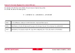
Data line in a Cross Section Assignment File in Leica GSI format

11....+QP000123  71....+00100000

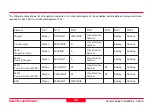
For the matter of completion, the following table is added as in the previous chapters.

1

1

I

W

.

e

li

F

t

n

e

m

n

g

il

A

l

a

t

n

o

z

ir

o

H

e

h

t

n

i

3

7

I

W

d

n

a

e

li

F

n

o

it

c

e

S

s

s

o

r

C

e

h

t

n

i

1

1

I

W

o

t

s

d

n

o

p

s

e

r

r

o

c

,r

e

b

m

u

n

n

o

it

c

e

s

s

s

o

r

C

1

7

I

W

.

n

o

it

c

e

s

s

s

o

r

c

r

a

l

u

c

it

r

a

p

e

h

t

r

o

f

e

g

a

n

i

a

h

c

g

n

i

n

n

i

g

e

B

t

n

e

m

e

l

E

1

1

I

W

1

7

I

W

t

n

e

m

n

g

i

s

s

A

r

e

b

m

u

N

n

o

it

c

e

S

s

s

o

r

C

n

o

it

a

t

S

Summary of Contents for GPS500

Page 1: ...Version 4 0 English 50 40 30 20 General Guide to RoadPlus GPS System 500 ...

Page 2: ...2 General Guide to RoadPlus 4 0 0en Congratulations on your purchase of a new Leica System GPS500 SystemGPS500 ...

Page 3: ...eneral Guide to RoadPlus 4 0 0en View of chapters Introduction Design Elements Data Files and Formats Terminology of Road Staking Staking a Road Alignment Glossary Index 6 8 22 44 48 67 72 View of chapters ...

Page 4: ...a Vertical Alignment File in Leica GSI format 29 The Cross Section Template File 31 Example for a Cross Section File in Leica GSI format 31 Header of a Cross Section File in Leica GSI format 32 Data line for a vertex in a Cross Section File in Leica GSI format 33 The Cross SectionAssignment File 35 Example for a Cross Section Assignment File in Leica GSI format 35 Header of a Cross Section Assignm...

Page 5: ...he Coordinate System 48 Receiverset up 49 Setting the units 49 Starting theApplication 50 Configuring Road Stakeout Parameters 50 Selecting the Files 52 Staking even stations of the HorizontalAlignment 53 Staking uneven stations of the HorizontalAlignment 56 Staking a Cross Section 59 Staking a Catch Point 63 Glossary 67 Index 72 Contents ...

Page 6: ...linear alignments with optional cross sectional information The program supports the staking out of individual points using horizontal and vertical alignments and cross sections station equations cross section assignment by station cross section definition cross section interpolation superelevation widening staking out of catch points ActivationoftheApplication The application is activated by an a...

Page 7: ...ual Getting Started with Real Time Surveys as well as the Technical Reference Manual If the material referenced is not thoroughly understood it is strongly adviced that you review them prior to proceeding with this application program Within this manual it is assumed that you are familiar with the operation of the system Introduction ...

Page 8: ...Design Elements General Guide to RoadPlus 4 0 0en DesignElements A road surface can be thought of three different types of design elements the horizontal alignment the vertical alignment the cross section ...

Page 9: ...n Easting Northing Beginning of Project BOP Station Easting Northing Sta tio nin g End of Project EOP Station Easting Northing Tangent Tangent Clothoïde The horizontal alignment defines the road axis of a project The constituting elements of a horizontal alignment are tangents straight segments circles clothoïdes spiral in out curve in out Each constituting element is defined by individual horizon...

Page 10: ...ry of the design elements for horizontal alignment is included in this chapter The Tangent straight line between two points It s end point is identical with the beginning of a curve or spiral The tangent is perpendicular to the radius of the curve The Curve circular curve with constant radius Sipral in spiral transition from tangent to curve Sipral out spiral transition from curve to tangent stati...

Page 11: ...sed for combinations such as curve curve in curve out curve or tangent spiral in curve in curve whereas spiral in out always connect a tangent with a curve curve in curve out Parameter A R radius of the connecting circular curve L length of the spiral in out or curve in out Sign convention for curves and spirals centre of curvature to left of centre line R resp A 0 centre of curvature to right of ...

Page 12: ...Point Curve VPC Station Elevation R Vertical Point Curve VPC Station Elevation parameter P Vertical Point Tangent VPT Station Elevation The vertical alignment gives information about the pattern of heights of the road axis as it is defined in the horizontal alignment The constituting elements of a vertical alignment are tangents straight segments circles parabolas Each constituting element is defi...

Page 13: ...etween two points It s end point is identical with the beginning of a curve or spiral The tangent is perpendicular to the radius of the curve The Curve circular vertical curve with constant radius The Parabola a parabolic vertical curve with constant rate of grade change Sign convention for curves and parabolas centre of curvature below the alignment R resp P 0 centre of curvature above the alignm...

Page 14: ...cimal units not percent negative for decreasing elevation with increasing station S any station chainage on the parabola S0 station chainage of the high low point of the parabola H height at any station S of the parabola H0 height of the high low point of the parabola whereas a is a parameter in the general equation for a parabola in mathematics Y aX2 bX c Y elevation of vertical curve above datum...

Page 15: ... alignment or actual elevation on each station The constituting elements are straight elements The points are called vertices You may optionally define slopes at the vertices most left and most right Points are definined by H and V H and slope in percentage H and slope ratio H horizontal distance from the centre line V vertical distance from the centre line vertical alignment or actual elevation m...

Page 16: ...ve for fill slopes The American style and road editor slope definition is slope ratio 1 slope H V Sign convention for cross sections Sign convention is based on horizontal and vertical alignments left or below centre line right or above centre line Slope ratio definition V H H cut slope V H fill slope V V H ...

Page 17: ... 832 0 450 725 0 550 725 0 619 254 Cross sections are assigned to stations not to sections One cross section is valid until a new one is defined at a station ahead Cross section definition can be at any station The stations need not necessarily correspond to stations where a design element starts or ends ...

Page 18: ... are mentioned here Widening increase decrease of road width with change in number of lanes Widening influences the shape of the cross sections RoadPlus has the ability to interpolate cross sections between beginng and end of the widening A B 0 020 000 C 0 190 000 widening 0 123 000 Interpolation 0 000 000 Cross Section View from above ...

Page 19: ... to RoadPlus 4 0 0en Superelevation modification of the normal pavement cross slope Intended to increase comfort and safety at speed A 0 348 832 0 450 725 B Interpolation Interpolation 0 393 000 0 427 000 Cross Section View from above ...

Page 20: ...gnment File These adjustments may be necessary when the horizontal alignment has been modified by inserting or removing a constituing element and the stationings in the Horizontal Alignment File were not recomputed This can be the case when editing manually or with a program which does no automatic recomputation Simply speaking station equations define leaving a gap or allow an overlap at certain ...

Page 21: ...new 0 470 000new 0 560 000 new 0 460 000 old 0 570 000 new 0 470 000 old 0 650 725 new 0 550 725 old Due to removing a constituing element the sequence of stationing misses some values If this is the case a gap equation forward station equation is required The station equation is of the form The stations between 0 450 725 and 0 550 725 will be ignored Where the sequence of stationing repeats some ...

Page 22: ...f superelevation points Furthermore if station equations are needed RoadPlus will read a file created for station equations and apply the appropriate corrections Since all RoadPlus project files are in GSI format the com mon extensions is gsi however they are distinguished by three letter file name prefixes which define the file type and must be used when creating the files The question marks in t...

Page 23: ...uting elements of a horizontal alignment build a so called Horizontal Alignment File The following is an example of a Horizontal Alignment File in Leica GSI8 format GSI16 is also supported A Horizontal Alignment File must contain at least a header and two elements The last element must be EOP Note that each line must end with a space and that a CR LF is required after the last data line ...

Page 24: ...COORD 1 4 I W r e s u y b d e n i f e d e b y a m s r e t c a r a h c I I C S A 8 m u m i x a m n o i t a c i f i t n e d i b o J 2 4 I W M N G I L A Z H e b t s u m y r t n e s i h T r e s u y b d e g n a h c e b t o n y a m e l i F t n e m n g i l A l a t n o z i r o H f o n o i t a c i f i t n e d I 3 4 I W D R O O C A T S e b t s u m y r t n e s i h T r e s u y b d e g n a h c e b t o n y a m ...

Page 25: ... s o p s i s u i d a r 2 8 I W d n a 1 8 I W y b d e n i f e d e r a s e c a l p l a m i c e d d n a s t i n u a t a D N O N 0 0 0 0 0 s i t c e j o r P f o d n E d n a s t n e g n a t r o f t l u a f e D 3 7 I W e l i F n o i t c e S s s o r C n i 1 1 I W o t s d n o p s e r r o C t n e m e l e c i r t e m o e g t x e n e h t o t d e n g i s s a n o i t c e s s s o r c f o r e b m u N n o i t a c...

Page 26: ...s s o r C r e b m u N g n i t s a E g n i h t r o N l a r i p S e v r u C o t t n e g n a T n o i t a t S N I R I P S 0 0 A n o i t c e S s s o r C r e b m u N g n i t s a E g n i h t r o N l a r i p S t n e g n a T o t e v r u C n o i t a t S T U O R I P S 0 A n o i t c e S s s o r C r e b m u N g n i t s a E g n i h t r o N l a r i p S 2 R 1 R e v r u C o t e v r u C n o i t a t S N I E V R U C ...

Page 27: ...e constituting elements of a vertical alignment build a so called Vertical Alignment File The following is an example of such file in Leica GSI8 format GSI16 is also supported An Vertical Alignment File must contain at least a header and two elements The last element must be EOP Note that each line must end with a space and that a CR LF is required after the last data line ...

Page 28: ...ACOORD 1 4 I W r e s u y b d e n i f e d e b y a m s r e t c a r a h c I I C S A 8 m u m i x a m n o i t a c i f i t n e d i b o J 2 4 I W M N G I L A V 0 e b t s u m y r t n e s i h T r e s u y b d e g n a h c e b t o n y a m e l i F t n e m n g i l A l a c i t r e V f o n o i t a c i f i t n e d I 3 4 I W D R O O C A T S e b t s u m y r t n e s i h T r e s u y b d e g n a h c e b t o n y a m e l...

Page 29: ...a m i c e d d n a s t i n u a t a D 1 7 I W t n e m e l e c i r t e m o e g g n i w o l l o f e h t f o e p y T 2 7 I W s a l o b a r a p r o f r e t e m a r a p P r o e v r u c g n i w o l l o f r o f s u i d a R e v i t a g e n e s i w r e h t o e v i t i s o p s i P r o s u i d a r e h t e n i l e r t n e c e h t e v o b a s e i l a l o b a r a p e v r u c a r o f t n i o p s u i d a r e h t f ...

Page 30: ...re required for each WI in a Vertical Alignment File t n e m e l E 1 1 I W 1 7 I W 2 7 I W 3 8 I W t n e g n a T n o i t a t S T H G I A R T S N O N 0 0 0 0 0 e t a n i d r O e v r u C r a l u c r i C n o i t a t S E V R U C 0 0 0 R e t a n i d r O a l o b a r a P n o i t a t S L O B A R A P 0 P e t a n i d r O P O E n o i t a t S P O E 0 0 0 0 0 N O N 0 0 0 0 0 e t a n i d r O ...

Page 31: ...ss section build a so called Cross Section or Template File The following is an example of such a file in Leica GSI8 format GSI16 is also supported A Cross Section File must contain at least one cross section 200 cross sections per file are allowed One cross section may be described by up to 64 vertices points Note that each line must end with a space and that a CR LF is required after the last da...

Page 32: ...ne header line per file The header line takes the following form 41 0EXAMPLE 42 TEMPLATE 1 4 I W r e s u y b d e n i f e d e b y a m s r e t c a r a h c I I C S A 8 m u m i x a m n o i t a c i f i t n e d i b o J 2 4 I W E T A L P M E T e b t s u m y r t n e s i h T r e s u y b d e g n a h c e b t o n y a m e l i F n o i t c e S s s o r C f o n o i t a c i f i t n e d I ...

Page 33: ...i l a t a d e h T 5 3 I W e n i l e r t n e c m o r f e c n a t s i d l a t n o z i r o H e n i l e r t n e c e h t f o t h g i r e h t o t t n i o p a s e t a c i d n i e c n a t s i d e v i t i s o p A e n i l e r t n e c e h t f o t f e l e h t o t t n i o p a s e t a c i d n i e c n a t s i d e v i t a g e n A 6 3 I W e n i l e r t n e c e h t m o r f e c n e r e f f i d t h g i e H e n i l e ...

Page 34: ...n e m e l E 1 1 I W 5 3 I W 6 3 I W 1 7 I W 2 7 I W x e t r e V t n e m n g i l a l a c i t r e v g n i s u n o i t c e S s s o r C r e b m u N l a t n o z i r o H t e s f f O l a c i t r e V t e s f f O T U C 0 0 0 0 0 L L I F 0 0 0 0 e p o l S x e t r e V l a c i t r e v t u o h t i w t n e m n g i l a n o i t c e S s s o r C r e b m u N l a t n o z i r o H t e s f f O n o i t a v e l E T U C 0 ...

Page 35: ...wing is an example of such a file in Leica GSI8 format GSI16 is also supported A Cross Section Assignment File belongs to a corresponding Cross Section File You must have a Cross Section Assignment File when using a Cross Section File The number of assignments is restricted to 100 per file A cross section remains valid until a new cross section is assigned A given cross section may be assigned mor...

Page 36: ...n i f e d e b y a m s r e t c a r a h c I I C S A 8 m u m i x a m n o i t a c i f i t n e d i b o J 2 4 I W T M N G I S S A e b t s u m y r t n e s i h T r e s u y b d e g n a h c e b t o n y a m e l i F t n e m n g i s s A n o i t c e S s s o r C f o n o i t a c i f i t n e d I 3 4 I W e l i F n o i t c e S s s o r C g n i d n o p s e r r o c e h t f o e m a N e l i f t n e m n g i s s a n a e s ...

Page 37: ...in the previous chapters 1 1 I W e l i F t n e m n g i l A l a t n o z i r o H e h t n i 3 7 I W d n a e l i F n o i t c e S s s o r C e h t n i 1 1 I W o t s d n o p s e r r o c r e b m u n n o i t c e s s s o r C 1 7 I W n o i t c e s s s o r c r a l u c i t r a p e h t r o f e g a n i a h c g n i n n i g e B t n e m e l E 1 1 I W 1 7 I W t n e m n g i s s A r e b m u N n o i t c e S s s o r C n...

Page 38: ...at GSI16 is also supported Note that each line must end with a space and that a CR LF is required after the last data line If you use the Leica program RoadEd for your editing you really should not need to use a station equation file because it will always attempt to adjust the stationings for you as you make changes You can also force it to re calculate the stationing using the Recalc Stationings...

Page 39: ...eader line per file The header line takes the following form 41 0EXAMPLE 42 0STAEQTN 1 4 I W r e s u y b d e n i f e d e b y a m s r e t c a r a h c I I C S A 8 m u m i x a m n o i t a c i f i t n e d i b o J 2 4 I W N T Q E A T S 0 e b t s u m y r t n e s i h T r e s u y b d e g n a h c e b t o n y a m e l i F n o i t a u q E n o i t a t S f o n o i t a c i f i t n e d I ...

Page 40: ...0450725 For the matter of completion the following table is added as in the previous chapters 1 4 I W r e b m u n n o i t a u q e n o i t a t S 2 4 I W d a e h a n o i t a t S 3 4 I W k c a b n o i t a t S t n e m e l E 1 4 I W 2 4 I W 3 4 I W n o i t a u q E r e b m u N n o i t a u q E n o i t a t S d a e h A n o i t a t S k c a B n o i t a t S ...

Page 41: ...and easy creation of new alignments or modification of existing ones It also supports checking alignments for errors and plotting alignments on a graph Some commercial road packages such as TopoCAD Sweden Geo11 Sweden GEOSECMA NT Sweden save the data directly in GSI format Other road packages have their own file format for which conversion programs to GSI exist for example Microstation with Interg...

Page 42: ...to be copied to the PCMCIA card If your computer has a PC card reader you can transfer the data files directly from the PC to the card If no PC card reader is available on the PC being used use the sensor transfer option in SKI Pro Format the PCMCIA card in the sensor Insert the card into the PC By using the Explorer copy the data files from the hard drive of the PC into the directory GSI on the m...

Page 43: ...ettings Right click on Sensor and choose Turn GPS Sensor on Right click on Sensor and select Transfer Any File Under Look in select the directory where the data files are kept Under Files of Type select GSI Under Sensor device select PC card Under Directory select GSI Highlight one file to be transferred since only one file can be transferred at a time Click the Transfer button For transferring th...

Page 44: ...road staking They may vary from country to country In order to make the chapter on staking a road alignment with the program RoadPlus easier to understand the basic terminology of one common way of road staking is introduced in this chapter The technical terms are indicated in the drawings and are also explained in words afterwards ...

Page 45: ... Terminology of Road Staking General Guide to RoadPlus 4 0 0en The Cut Centre Line Catch Point Original Ground Finished Road Level Existing ground level to be removed verge carriage way slope Hinge Point ...

Page 46: ...46 Terminology of Road Staking General Guide to RoadPlus 4 0 0en The Fill Original Ground Finished Road Level Centre Line Catch Point Fill to be placed rocks earth verge carriage way slope Hinge Point ...

Page 47: ...ce is the undisturbed surface before project construction The Finished Road Level describes the final road Since cuts fills start from the original ground there must be a physical point on each desired cross section station where the finished design shape of the roadway cut fill intersects with the existing ground surface This point is called catch point If the catch point is marking the catch of ...

Page 48: ...rect result when working with RoadPlus the GPS jobs must be orientated to the same local grid coordinate system as the alignment to be staked out This is accomplished by attaching the current coordinate system to the job Depending on the coordinate system you will either use pre defined parameters or determine the required transformation parameters either on the sensor or in SKI Pro On how to set ...

Page 49: ...et up properly running a suitable configuration set and the data transfer from the reference to the rover must be working For detailed information please refer to Getting Started with Real Time Surveys and the Technical Reference Manual The GPS sensors must be configured in the same coordinate units as those of the generated gsi files Check the sensor settings in panel CONFIGURE Units The units mu...

Page 50: ... 10 RoadPlus CONT F1 DFLT F5 This sets the default values for all input fields It may be necessary to adapt them according to your needs Beg Station Beginning station chainage from which you want to start working End Station End station chainage where you want to finish Sta Incr Station increment Type in the interval at which stations have to be staked Vert Shift Enter a vertical shift value if re...

Page 51: ...erelevation and widening possible Crs Movemnt There are three choices Left Right Right Left and None The direction chosen is for automatic selection of the next station of a cross section Points can still be staked out at any desired direction along the cross section None is for no automatic pre selection Hinge Mode Method for the catch point determination The options are Normal and Not from End P...

Page 52: ... one The default is none since a Cross Section File is optional Crs Assign Select a Cross Section Assignment File if you have one The default is none since a Cross Section Assignment File is optional In order to use a Cross Section Assignment File a Cross Section File must have been selected Station Eq Select a Station Equation File if you have one The default is none since a Station Equation File...

Page 53: ...Vertical Offset to apply to the current chainage NEXT F2 displays the next station and its element according to the defined station incrementation PREV F3 displays the previous station and its element according to the defined station incrementation XSEC F4 Starts cross section staking See chapter Staking a Cross Section STA F5 Station and offset calculation for a known point select from point ID l...

Page 54: ...to the surface If the point elevation in the previous panel has been changed the value for cut applies to this new elevation Navigate to the correct point Place the antenna pole at the location Be sure that the antenna is levelled Once the desired point is located OCUPY F1 The current Point ID may be accepted or changed 3D Quality Observe the position quality indicator Data should not be recorded ...

Page 55: ...re to stake out additional stations along the alignment Once the last point EOP in the Horizontal Alignment File has been staked and you continue anyway this confirmation message will appear OK F5 and then CONT F1 to continue anyway or ABORT F1 and ESC to exit the panel For complete information on how to use STAKE OUT please refer to chapter Real Time Rover Staking Out in the Techni cal Reference ...

Page 56: ...Offset Horizontal offset to be applied to current station Looking in the direction of increasing station apply the right hand positive rule V Offset Vertical offset to be applied to current station A positive offset is above a negative offset is below the normal height of the current station CONT F1 Panel ROAD Point Coords Here the design coordinates for the current uneven station are displayed If...

Page 57: ...alue for cut applies to this new elevation Navigate to the correct point Place the antenna pole at the location Be sure that the antenna is levelled Once the desired point is located OCUPY F1 Panel STAKE OUT Occupy Point The current Point ID may be accepted or changed 3D Quality Observe the position quality indicator Data should not be recorded until you are satisfied with this value When you are ...

Page 58: ...l ROAD Station Offset Here the station has incremented to the next regular station according to the defined station increment value For complete information on how to use STAKE OUT please refer to chapter Real Time Rover Staking Out in the Techni cal Reference Manual ...

Page 59: ...EXT F2 PREV F3 or typing manually XSEC F4 If the assigned cross section for the selected station is not available in the cross section file the following information message appears Staking a Cross Section Initially the panel looks as shown above From the Cross Section Assignment File RoadPlus knows which cross section to use for the entered station There may however be cases where you wish to app...

Page 60: ...the centre line RoadPlus interpolates within the cross section V from CL The vertical distance of the point from the centre line To stake any point along the cross section which is not pre defined in the cross section file enter its vertical distance from the centre line H Offset Horizontal offset to be applied to current station Looking in the direction of increasing station apply the right hand ...

Page 61: ...ross section which you want to stake CONT F1 Panel ROAD Point Coords Here the design coordinates for the selected station are displayed If in the panel ROAD Configuration Edit Height is set to YES the focus will be on the Elevation and the value can be changed before staking STAKE F1 You will be taken to the Stakeout graphics screen Panel STAKE OUT xxx whereas xxx is the name for the file stake po...

Page 62: ... Left This is the range to the selected point and is updated as the antenna pole is moved Cut Fill Indicates the cut fill to the surface If the point elevation in the previous panel has been changed the value for cut applies to this new elevation Once in the Stakeout graphics screen navigate to the correct point as normal Place the antenna pole at the location Be sure that the antenna is levelled ...

Page 63: ...OUT please refer to chapter Real Time Rover Staking Out in the Techni cal Reference Manual Staking a Catch Point The stakeout functionallity for a catch point can be accessed from the panel ROAD Cross Sections On how to get there follow the instructions in chapter Staking a Cross Section Panel ROAD Cross Section SHIFT CATCH F3 Panel ROAD Catch Point Station The selected station of the horizontal a...

Page 64: ...rate the individual values are updated automatically Note that the highest update rate in this panel is 1 second even though the general update rate might be set to a value 1 second The catch point has been found when the V from XS and Station are zero Navigate to the correct point Place the antenna pole at the location Be sure that the antenna is levelled H from CL V from XS H fm Hinge V fm Hinge...

Page 65: ...on template for which you are about staking a reference point The number and letter right of the scroll bar express how many positions left L or right R of the centre line you are working or if you are on the centre C Station The current station selected for stakeout Cross Sect Name of the cross section template currently in use Station Horizontal distance from displayed station H fmCatch The hori...

Page 66: ...ation Height of the actual pole position According to the update rate the individual values are updated automatically Note that the highest update rate in this panel is 1 second even though the general update rate might be set to a value 1 second Either navigate to a point which is suitable as reference point or until H and V from catch hinge centre line slope show required values Place the antenn...

Page 67: ...way or travel way Catch Point A point marking the intersection between the design surface and the original ground Centre Line The plan view alignment also called Horizontal Alignment Chainage The cumultative distance along the horizontal alignment frequently but not always starting at zero Also called station Clothoïde A horizontal curve with constantly linear increasing curving Defined by A2 R x ...

Page 68: ...e project in areas of excavation with the design surface below original ground Design Surface The intended shape of the completed project Equation Required for a point on the horizontal alignment where the stationing is discontinuous Gap equations and overlap equations are distinguished Fill Slope The surface of the project in areas of fill with the design surface above original ground Finished Ro...

Page 69: ... alignment or cross section Offset Point See reference point Original Ground The undisturbed surface before project construction is started as well as the actual shape of the project at the current stage of construction also called original surface or ground surface Original Surface See original ground Overlap Equation A type of station equation handling overlaps in the stationing after inserting ...

Page 70: ...rve R1 R2 n parameter A Spiral Out A gradual horizontal spiral transition from a curve to a tangent R1 n R2 parameter A Station The cumultative distance along the horizontal alignment frequently but not always starting at zero Also called chainage Parabola A parabolic arc Exists only on vertical alignments Profile See cross section Reference Point A second point often marked nearby the catch point...

Page 71: ...l pavement cross slope Intended to increase comfort and safety at speed Verge Next to the carriage way the part of the road with usually a slightly higher slope ratio Also called shoulder Tangent A straight line connecting two position points XY or height points Z It touches a circle curve or spiral in one point and is perpendicular to the radius of the circle curve or spiral in this point Top of ...

Page 72: ...Section Template File 22 31 Cross Section Assignment 17 Cross Section Assignment File 22 35 Curve 10 13 67 Curve In 11 68 Curve Out 11 68 Curvilinear 68 Cut 45 Cut Slope 68 D Design Elements 8 Design Surface 68 E Equation 68 F Fill 46 Fill Slope 68 Finished Road Level 45 46 47 68 Forward Station Equation 68 G Gap Equation 21 68 Grade 69 Ground Surface 69 H Hinge Point 45 46 47 69 Horizontal Alignm...

Page 73: ... 70 RoadEd 41 Roadway 70 S Shoulder 47 70 Sipral In 10 Sipral Out 10 Slope 45 46 47 70 Slope Ratio 16 Spiral 70 Spiral In 70 Spiral Out 70 Station 70 Station Ahead 21 71 Station Back 21 71 Station Equation 20 71 Station Equation File 22 38 Superelevation 19 71 T Tangent 10 13 71 Toe of Bank 47 71 Top of Bank 47 71 Travel Way 71 V Verge 45 46 47 71 Vertical Alignment 12 71 Vertical Alignment File 2...

Page 74: ...onmental Management Systems ISO standard 14001 Total Quality Management Our commitment to total customer satisfaction Ask your local Leica agent for more information about our TQM program Leica Geosystems AG CH 9435 Heerbrugg Switzerland Phone 41 71 727 31 31 Fax 41 71 727 46 73 www leica geosystems com Printed in Switzerland Copyright Leica Geosystems AG Heerbrugg Switzerland 2001 Original text 7...

Reviews: