background image

Page 166 

Job Editor 

Group 8 

Release R1.06 


JET3up 


7.4.1


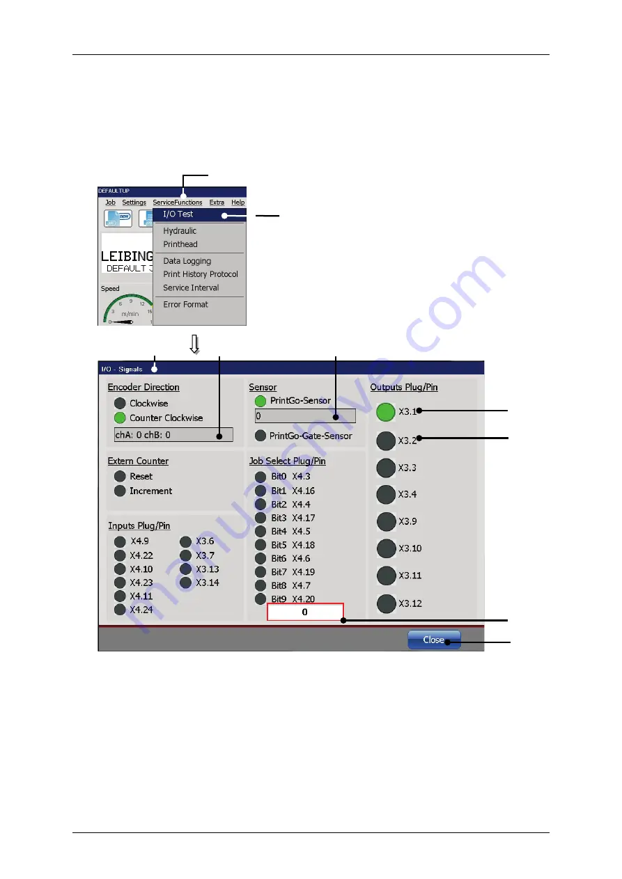
  I/O Test - Signal test 


With the option 

<I/O Test>


(2)

 the dialog box „I/O-Signals 

(3)

“ is displayed. The 

dialog box shows the states of the inputs and outputs of the device. 

Figure 71 

I/O-Signal test  


1 – Drop-down menu<ServiceFunctions>  5 – Signal counter for PrintGo signals 


2 – Option <I/O-Test> 

6 – Status indicator <I/O active> 


3 – Dialog box <I/O-Signals> 

7 – Status indicator <I/O inactive> 


4 – Signal counter for channels A and B of 

the encoder 

8 – Decimal value of the current Job 

Select address 


9 – <Close> Button  


Summary of Contents for JET3 up

Page 1: ...Operating Manual V1 06 Please keep for future reference ...

Page 2: ......

Page 3: ...ersonal protective equipment 23 2 8 Protective devices and safety concept 23 2 9 Safety measures at the place of installation 23 2 10 Dangers through consumables 25 2 11 Conformity 28 3 Accident prevention 30 3 1 Storage and handling 30 3 2 First aid measures 31 3 2 1 General first aid 31 3 2 2 First aid in case of contact with consumables 31 3 3 Fire fighting measures 32 3 3 1 Procedure in case o...

Page 4: ...47 5 4 Start up Commissioning 49 5 4 1 Remove transportation safety devices Step 1 49 5 4 2 Fill reservoir tank Step 2 51 5 4 3 Carry out filling routine Step 3 54 5 4 4 Setting of the external print head ventilation optional equipment 57 5 5 Interfaces 58 5 5 1 Ethernet connection 59 5 5 2 Interface X5 PrintGo 59 5 5 3 Interface X1 Encoder 61 5 5 3 1 Description and configuration 61 5 5 3 2 Mecha...

Page 5: ...n 83 6 5 4 Switch off device 85 6 6 Windows and menu elements 86 6 7 Optional equipment 89 6 7 1 External head print ventilation assembly and function 89 7 Data entry Programming 91 7 1 General 91 7 2 Job administration 92 7 2 1 Create a new job 93 7 2 2 Open job to edit 94 7 2 3 Edit current job 96 7 2 4 Load Job to print 97 7 2 5 Create new job list 99 7 2 5 1 Create new job lists Example Extern...

Page 6: ... user 160 7 3 5 1 2 Definition of password 160 7 3 5 1 3 Definition of access privileges 161 7 3 5 2 Lost password 162 7 3 6 Password protection and Password prompt 162 7 3 7 Password activation 164 7 4 Service functions 165 7 4 1 I O Test Signal test 166 7 4 2 Hydraulic Printhead and special functions 167 7 4 3 Printhead functions 169 7 4 3 1 Jet monitoring Ink Flow Sensor active 169 7 4 3 2 Ink ...

Page 7: ...og in log out dialog box 194 7 5 3 2 Login or change user 196 7 5 3 3 User log out 197 7 5 4 Interface settings 198 7 5 5 Font editor 200 7 5 6 Graphic editor 206 7 5 6 1 Edit tools 207 7 5 6 2 File management 208 7 5 6 3 Drawing tools 209 7 5 6 4 View menu 210 7 5 6 5 Load existing graphic 211 7 5 6 6 Save graphic Save graphic as 212 7 5 6 7 Graphic editor Settings 214 7 5 6 8 Create and process ...

Page 8: ...s 242 8 3 2 Load job to print 244 8 3 3 Close job editor 246 8 4 Object settings 247 8 4 1 Contrast value 248 8 4 2 Bold level Bold text 249 8 4 3 ICG value Inter Character Gap 250 8 4 4 Orientation and mirroring 251 8 4 5 Printout options 252 8 4 6 Counter assignment 253 8 4 7 Prompt field 257 8 5 Job settings 260 8 5 1 Print style Font parameters 261 8 5 1 1 Print height 261 8 5 1 2 Font width S...

Page 9: ...ed 285 8 5 3 5 Speed dependent output 286 8 5 3 6 Speed measuring with two sensors 288 8 5 4 Date change offset 290 8 6 Job editor settings 291 8 7 Printing elements 293 8 7 1 Bar codes 293 8 7 1 1 Bar codes Basics about 294 8 7 1 2 Bar codes Object creation and properties 297 8 7 1 3 Bar codes Global settings 298 8 7 1 4 Bar codes Bar code settings 298 8 7 1 4 1 Bar code settings Bar code format ...

Page 10: ... 333 8 7 5 1 2 Extern Text fixed length Object creation and properties 335 8 7 5 1 3 Extern Text fixed length Printout Deleting the input buffer 339 8 7 5 2 Extern Text variable length 343 8 7 5 2 1 Extern Text variable length Interface settings 343 8 7 5 2 2 Extern Text variable length Object creation and properties 343 8 7 5 2 3 Extern Text variable length Printout Deleting the input buffer 348 ...

Page 11: ...Taking out of operation Dismantling 381 11 1 Taking out of operation 381 11 2 Dismantling Disposal 381 12 Appendix 382 12 1 Circuit diagrams of the interfaces 382 12 2 Connection examples for the interfaces 385 12 2 1 Interface X 3 Outputs 385 12 2 2 Interface X 4 Inputs 386 12 2 2 1 Increment Counter Signal PIN 386 12 2 2 2 Reset Counter Signal Example with pushbutton 386 12 2 2 3 Jobselect Input...

Page 12: ...sport start up 41 6 Operation 67 Design and Structure of the printer 67 Functional principle 68 Safety instructions 71 Basic operation procedures 80 Window and menu elements 86 Optional equipment 89 7 Data entry 91 8 Job editor 232 9 Disorder Trouble shooting 365 10 Setting up Maintenance 367 11 Taking out of operation Dismantling 381 12 Appendix 382 Circuit diagrams of the interfaces 382 Connecti...

Page 13: ...ding Systems Daimlerstraße 14 D 78532 Tuttlingen Federal Republic of Germany Phone 49 74 61 92 86 0 Fax 49 74 61 92 86 1 99 E mail vertrieb leibinger group com Service hotline phone 49 74 61 92 86 8 63 Service hotline fax 0 74 61 92 86 8 69 Service hotline e mail service leibinger group com American Branch Office Paul Leibinger Numbering Machine LTD 2702 B Buell Drive East Troy WI 53120 USA Tel 01...

Page 14: ... the form of technology hardware software as well as the corresponding materials and manual extracts as a result of innovative further development of our devices Texts illustrations and technical drawings have been compiled with the greatest of care Nevertheless errors cannot be excluded Consequently no warranty can be assumed for the correctness of the content of this manual and no claims can be ...

Page 15: ...lectricity Risk due to flammable materials Risk due to pressure Risk due to electrostatic discharges Risk due to potentially explosive atmospheres Risk due to irritation of the respiratory organs Risk due to materials hazardous to health Risk of explosion Risk of hand injuries Smoking ban Comply with the operating instructions Wear protective gloves Wear safety glasses Important user information S...

Page 16: ...d or from incorrect operation INFORMATION Please pay particular attention to the safety instructions of the groups Safety instructions and accident prevention when handling consumables ink and solvent Our devices are subjected to a quality control in our plant prior to delivery If despite this the device or parts of it should be damaged or their function disturbed please advise us of this as fast ...

Page 17: ...rom the order confirmation The warranty presupposes that the device or the installation is operated correctly in accordance with the available warranty conditions and any possible additional manuals and descriptions prepared by us At this point we wish to make explicit reference to the fact that it is only when using solvent and ink from Paul Leibinger GmbH Co KG that the optimum operating charact...

Page 18: ...Page 16 Introduction Group 1 Release R1 06 JET3up ...

Page 19: ...lly trained and qualified about the handling with ink and solvent Before the first usage of the printer in particular the operating manual as well as the safety data sheets of the ink and solvent have to be read and noted Operational and safety checks of the installation were carried out before it left the factory In case of improper handling or misuse however there are dangers for the health of t...

Page 20: ...ay lead to a severe impact on health or even life threatening injuries CAUTION In conjunction with the signal word Caution the respective symbol represents a potentially dangerous situation Non compliance with these instructions may lead to light injuries or material damages ATTENTION Relating to the signal word Attention the respective symbols mean a possibly dangerous situation Ignoring the advi...

Page 21: ...he observance of all instructions in this manual Using the installation for other purposes is considered contrary to its intended use For safety reasons conversions and alterations are only admissible following consultation with the manufacturer Repairs to the device must only be carried out with original replacement parts The manufacturer shall not be liable for damage resulting from use for othe...

Page 22: ...Page 20 Safety Group 2 Release R1 06 JET3up 2 4 Safety sticker Figure 1 Safety sticker Safety sticker ...

Page 23: ...to operate the inkjet printer professionally The operator is responsible for third parties in the working area of the inkjet printer The owner operator must make this operating manual accessible to the printer operator and has to ensure that the operator has read and understood it Personnel in training can work on or with the inkjet printer only when supervised by an experienced operator ...

Page 24: ...TRICAL WORK The electrical and electronic components of the high performance printer are under voltage The device must only be opened by trained personnel or by Leibinger service technicians Prior to the opening of the device the device must be switched off and the mains plug removed ...

Page 25: ...t creepage current Plastic containers are arranged in the field of metal surfaces PE potential HV and ink cutoff as well as nozzle sealing at HV flashovers 2 9 Safety measures at the place of installation A place of setting up must be selected with sufficient load bearing capacity and stability When setting up it must be observed that sufficient movement space is available for the operating and se...

Page 26: ...ability insurance association guideline Operate the inkjet printer only outside of explosive atmospheres in a well ventilated area Inside the printer solvents are processed ensure sufficient ventilation The operator has to ensure that the MAK values noted on the safety data sheets won t exceed The printer ventilation must not be impaired do not cover or close the ventilation gills on the back pane...

Page 27: ...formation leaflets of the inks and solvents used CAUTION FIRE HAZARD Ink and solvent are highly flammable materials Inks are colored printing liquids on basis of solvents The safety instructions on the bottles of the consumables as well as the operating manual and also the safety data sheets must be noted to avoid any danger for people and environment For handling this consumables ink and solvent ...

Page 28: ...product may become statically charged Use a grounded line to transfer from one container to another An uncluttered clean working environment and regular safe disposal of waste materials minimize the risk of spontaneous ignition and other fire hazards If the printer is ever operated in a way that allows it to print into a beaker the beaker must be made of conducting material and be securely connect...

Page 29: ...he accumulation of dried ink and clean the working area regular Special hints about inks based on nitro cellulose This inks remain highly flammable even when they are dry If there has been an accumulation of dried ink do not use ferrous metal iron or steel scrapers to remove it as they can produce sparks If dry nitro cellulose based ink ignites it will generate its own oxygen and can only be extin...

Page 30: ...netic compatibility EMC part 6 3 Generic standards Emission standard for residential com mercial and light industrial environments For that product the relevant technical documentation were compiled according to Annex VII part A of the machinery directive on a resended request this documents can be transmitted to national authorities per CD Name and address of the person who is authorised to arran...

Page 31: ...Group 2 Safety Page 29 JET3up Release R1 06 ...

Page 32: ...t be conductive STORAGE Observe the marking information Store at 5 to 25 C in a well ventilated location at a safe distance from heat and ignition sources and direct sunlight Do not smoke Do not grant access to unauthorised persons Open containers must be properly closed and stored upright in order to avoid leakage Smoking eating and drinking must be forbidden in the storage and working areas Alwa...

Page 33: ...jured person s alone Additional measures Instruct the fire department or ambulance personnel Turn away curious onlookers 3 2 2 First aid in case of contact with consumables EYES Contact lenses must be removed Rinse thoroughly with pure fresh water for at least 10 minutes keep eyelids spread and call a doctor SKIN Remove contaminated clothes Wash skin thoroughly with soap and water or with a brande...

Page 34: ...y calm Report the fire WHO is reporting WHAT happened WHERE did it happen HOW MANY persons are affected or injured Wait for potential questions Activate the fire alarm Safety Bring endangered persons to safety Close doors Follow marked escape routes Do not use the elevator Comply with instructions Additional measures Attempt to extinguish the fire Instruct the fire department personnel Turn away c...

Page 35: ...xposed to the fire with spray water RISK OF FIRE AND EXPLOSION As the product contains combustible organic constituents a thick black smoke develops in the event of fire that contains dangerous combustion products Decomposition products can constitute a danger to health Extinguishing waste water must not enter the waste water channels or waters PROTECTIVE MEASURES If necessary suitable independent...

Page 36: ...NMENTAL PROTECTION MEASURES DO NOT allow to enter waste water channels or waters Should the product enter waste water channels or the drainage system the local water supply authority must be informed immediately In the event of contamination of streams rivers or lakes inform the national water authorities Vapour is heavier than air and can spread out on the ground In combination with air it can fo...

Page 37: ...Group 3 Accident prevention Page 35 JET3up Release R1 06 ...

Page 38: ...el cabinet Print head SK6 Length total 212 mm diameter 43 mm Option Print head SK4 Length total 265 mm diameter 43 mm Length of the print head lead 3 m as option 6 and 10 m available Weight 1 5 kg Any fitting position also for overhead conveyor applications Figure 3 Dimensions Print head SK6 Print head SK4 Option Protection class IP 54 as option IP 65 43 mm 286 mm 565 mm 446 mm 486 mm 344 mm 212 m...

Page 39: ...e humidity non condensating 4 4 Interfaces Inputs Outputs Product sensor input NPN PNP 24V Incremental encoder input TTL 5V HTL 24V RS422 5V Inputs 6 digitals free selectable 10 inputs for ext job selection Outputs 8 digitals e g for alarm re filling etc Interfaces Ethernet Industry standard M12D Serial Interface V24 RS232 up to 115 200 Baud USB 4 5 Performance parameter Printing capacity Characte...

Page 40: ...ckwards Symbols mirror inverted Symbols mirror inverted and upside down Symbols mirror inverted upside down and text backwards Alternating readable font reverse bold text inverse 4 8 Font combinations All fonts can be presented in one writing in the requested matrix 4 9 Function Full automatic function by The automatic nozzle seal guarantees that the print head is ready to print immediately after ...

Page 41: ...counters Current date and time printing original date Free programmable graphics logos creatable in the integrated editor Jobeditor allows the saving and calling of texts and all printing relevant parameters Programmable batch processing of jobs and bonding of several jobs External Text function Variable text Data base processing Replacements all date time and counter functions are codable by repl...

Page 42: ...Page 40 Accident prevention Group 4 Release R1 06 JET3up ...

Page 43: ...ote Storage temperatures below 5 C and above 50 C as well as storage at outside are not admissible and can lead to damage 5 2 Mounting WARNING Danger of explosion The device must not be operated in potentially explosive areas The installation has to be carried out according to the installation instructions of the manufacturer Precautions regarding electrostatics have to be carried out WARNING INST...

Page 44: ...vice has four fastening possibilities for secure seting up and should be screw connected at the place of setting up Figure 5 Fastening posibilities ATTENTION A place of setting up with sufficient load bearing capacity and stability must be chosen Prior to assembly the place of setting up must be cleaned of dirt and contamination residue of lubricants etc 120 120 355 ...

Page 45: ...ration INFORMATION You will find further information regarding the initialization in the chapter 6 5 2 First initialization of the device 5 3 2 Grounding Potential equalization WARNING Grounding Potential equalization In case of a non existing grounding or that the grounding of the printer is not carried out properly this could cause serious injury or death and it can also cause malfunctions or da...

Page 46: ...n behind the round grounding symbol label 7 on the lower left hand side of the cabinet of the printer Figure 6 Grounding scematic and grounding point Grounding schematic 1 Printer cabinet 4 Grounding line 7 Grounding symbol label 2 Installation 5 Umbilical 3 Print head 6 Grounding point M6 5 7 6 4 1 3 2 Ground earth ...

Page 47: ...in the lightning protection concept of the operator Further more protection measures regarding electrostatics have to be made 5 3 4 Print head WARNING Risk of fire and injury Inflammable Combustible gases and liquids cause serious burns Sources of ignition must be kept away from the print head Ink escapes from the head aperture Spraying of ink into the eyes can cause blindness Eye protection is ne...

Page 48: ...m statistically loop 200 mm and dynamically not below R 150 mm loop 300 mm Torsional shear stress must be avoided The distance of the print head to the product depends on the required character height As smaller the required character height as smaller the distance of the print head to the product smaller distances produce better type quality Note In general a distance of round about 8 10mm is rec...

Page 49: ...lation for print head works For technical reasons the ink of a continuous ink jet printer is charged with high voltage during the printing process In case of inappropriate handling the static charged ink may be an ignition source In combination with flammable ink and solvent this could pose a fire or explosion hazard Therefore for some works a ground cable is required Basically there are two situa...

Page 50: ...y Fire hazard Print head Explosion hazard Service tray Leibinger Cleaning station Electrostatic sensitive device Ground cable Connect print head with service tray Cleaning the print head Fire hazard Explosion hazard Electrostatic sensitive device Ground cable Connect print head with service tray ...

Page 51: ...es Step 1 Fill the reservoir tank Step 2 Carry out the function Filling Routine Step 3 5 4 1 Remove transportation safety devices Step 1 The pumps and valves of the hydraulic system are secured with cable ties These have to be absolutely removed Proceeding Dismantle the backplane of the hydraulic cabinet 1 by loosing the fixing screws 2 ATTENTION The cable tie at the main filter 3 should not be re...

Page 52: ...Page 50 Transport Start up Group 5 Release R1 06 JET3up Figure 8 Remove transportation safety devices 1 Backplane Hydraulic cabinet 2 Fixing screws 3 Main filter 1 2 3 ...

Page 53: ...nks for ink and solvent are installed beneath the cover flap of the refill unit The two reservoir tanks are monitored by level sensors They are always unpressurized and can be opened in every device condition The reservoir tanks and the sealing cap are color coded and labelled to avoid any mistakes in filling Additionally the sealing caps are marked with the ink no or solvent no which are admissib...

Page 54: ...t is necessary Read the safety data sheets and the personal protective equipment rules and regulations ATTENTION The sealing of the refill bottle must not be opened Open the lid 2 of the reservoir tank unit 1 Open the screw cap of the solvent tank 4 and of the refill bottle 5 Put the refill bottle on the solvent tank The seal of the bottle will be breached and the closing valve of the tank will op...

Page 55: ...ss Indicating label Marking of reservoir tanks Marking of the admissible ink Example Marking of the admissible solvent Example 1 Reservoir tank unit 4 Reservoir tank Solvent 2 Hinged cover lid 5 Refill bottle Solvent 3 Reservoir tank Ink 6 Refill bottle seal 3 1 4 N º 77001 00001 N º 70000 00001 2 5 6 ...

Page 56: ...r filling the consumables you have to carry out the filling routine Proceeding Figure 10 Filling routine Step 1 1 TFT Touch Display 5 Tab Spec func Tools 2 Message Initialization 6 Button Fill up Routine 3 Message Emergency Shutdown 7 Message Fill up Routine 4 OK Button 8 next Button 1 2 3 4 5 7 6 8 ...

Page 57: ...e filling routine Note This process takes approx 10 minutes After finishing the process an according message 9 is displayed Press the button OK 10 to finish the routine Press the button Close 11 to leave the menu Special functions Tools The message Hydraulic control 12 is faded in Note For leaving the service menu the hydraulic control will be turned on again automatically Press the button OK 13 t...

Page 58: ...6 JET3up Figure 11 Filling routine Step 2 Message during the routine 9 Message Fill up Routine finished 13 OK Button 10 OK Button 14 Main window 11 Close Button 15 Message Bleeding 12 Message Hydraulic control 16 Button Cancel 14 12 10 13 11 15 16 9 ...

Page 59: ...e printer Proceeding Turn the adjusting knob 2 of the pressure regulator valve 1 until the necessary pressure of 1 4 bar is reached Figure 12 Setting the pressure regulator Setting the pressure regulator external head ventilation 1 Pressure regulator valve 3 Indicating label 2 Adjusting knob 4 Manometer INFORMATION Supplementary information for the assembly and function can be found in the chapter...

Page 60: ...ble with dry oil free and filtered compressed air Filtering 8 µm The use of otherwise prepared compressed air can lead to damage and malfunctions 5 5 Interfaces The following interfaces are available on the rear side of the electronics cabinet Figure 13 Interfaces Interfaces 1 Electronic cabinet 5 Interface X3 digital outputs 2 Interface X5 PrintGo 6 Interface X2 Serial Interface 3 Interface X1 En...

Page 61: ...X5 provides the connection of an external PrintGo signal All common product detectors e g light barrier product sensor ect 24V NPN as well as 24V PNP switching can be connected The PrintGoGate input requires a PNP sensor Regarding the software you can select additionally if the positive edge or the negative edge should be used for the release of the printout Note To inform the JET3up when a print ...

Page 62: ...r NPN sensors Input level High 20 up to 28V or high resistance Input level Low 6V up to 9V Minimum pulse duration 100µS Input resistance 6 8kOhm PrintGo Gate For PNP sensors Input level High 15 up to 30V Input level Low 3 5V up to 3 5V or high resistance Minimum pulse duration 100µS Input resistance 6 8 kOhm INFORMATION You will find a circuit diagram of the interface in the appendix of this manua...

Page 63: ... Input level High 2 4V up to 5 5V Input level Low 0 5V up to 0 7V Max frequency 500 kHz Input resistance 1 MOhm HTL Input level High 12 up to 28V Input level Low 0 5 up to 3 5V Max frequency 500 kHz Input resistance 4 kOhm INFORMATION The signal type which should be used as encoder source has to be set in the software of the JET3up under Settings Basic Settings Encoder Interface You will find a ci...

Page 64: ...ON Risk of injury The shaft encoder has to be installed or mounted that no risks of injury can occur 5 5 4 Interface X4 Digital inputs 19 inputs for special functions are available whereof the connections of 6 inputs can be freely selected Plug assignment Pin connection Pin Designation Pin Designation 1 Reset Counter 14 24V 1 2 Increment Counter 15 GND Reset Counter Increment Counter 3 Jobselect 0...

Page 65: ... release the assigned function at the X4 plug Function Minium pulse width Open nozzle 300ms Close nozzle 300ms Print start 500ms Print stop 500ms Turn off printer 750ms Mirrored horizontally 200ms Gauger synchronization signal 200ms INFORMATION The function allocations of the inputs 0 up to 5 happens by the software of the JET3up in the menu Settings I O Settings Inputs You will find a circuit dia...

Page 66: ...n on resistance max 0 28 Ohm Features Short circuit proof Overcurrent and excess temperature proof INFORMATION The function allocations of the outputs is carried out with the software of the JET3up in the menu Settings I O Settings Outputs You will find a circuit diagram of the interface in the manual appendix 1 All 24V outputs which are designated with 1 are protected by a self reset fuse with 70...

Page 67: ...ific software for the data management and for the remote control of the printer Plug assignment Pin connection INFORMATION The function allocations of the outputs is carried out with the software of the JET3up in the menu Settings I O Settings Outputs You will find a circuit diagram of the interface in the manual appendix Pin Designation Pin Designation 1 NC 6 Connected with 4 2 RxD 7 RTS 3 TxD 8 ...

Page 68: ...ion With an optional bar code scanner connected to the USB port it is possible to emulate keyboard inputs with barcodes in order to avoid typing errors Commands read from bar codes to load and execute pre installed print jobs If the bar code scanner is connected to the USB port it is used to emulate keyboard inputs With a bar code scanner connected to the RS 232 interface of the JET3up there are f...

Page 69: ...uch Display as well as the controller board The large central arranged TFT Touch Display describes the interactive interface for the operator This central entry medium with its extensive 10 4 color display with backlight allows a clear self explaining operator guidance without additional keys and switches In the hydraulic cabinet you find all components which are required for the transportation an...

Page 70: ...flection field into a gutter In the gutter the drops are sucked up by a suction pump and fed back into the ink tank Depending on the application alphanumeric data and graphics can be entered with the TFT touch display INFORMATION Data for font and texts are stored in the device even in the event of power failure If required it can be called up altered or deleted quickly and easily Further more all...

Page 71: ...ld Here those droplets that were previously charged in the charging electrode are deflected The drops that have not been charged fly straight ahead into the gutter Here they are sucked up and fed back to the circular flow of ink The charged drops are only deflected in one direction the other direction is performed by the product to be inscribed 6 2 5 Creation of a character Each character is defin...

Page 72: ...tion process X X 1 Character height created by drop deflection Character E build with a 7 x 5 matrix Rel movement direction of the description area Drop brake off point Gutter Deflector plate Charge electrode with deflector electrode Character width created by the rel movement of the description area Nozzle jet Oscillator ...

Page 73: ...r belt 4 Sensor 6 3 Safety instructions WARNING Risk of fire and injury Inflammable Combustible gases and liquids cause serious burns Sources of ignition must be kept away from the print head Ink escapes from the head aperture Spraying of ink into the eyes can cause blindness Eye protection is necessary 3 5 4 2 1 Direction of conveyance ...

Page 74: ...ducts minutes indicator 12 Indicator for general status information 6 Date Time indicator 13 Printstart button 7 Off Shut down button 14 Printstop button Title bar 1 The title bar of the main window shows the name of the active print job and indicates the currently logged in user The logged in user is only displayed when the Password active option is selected Please see chapter 7 3 5 Password sett...

Page 75: ... print job in What you see is what you get mode Printing speed indicator or Products per minute indicator 5 this indicator shows either the current printing speed or how many products are currently printed per minute Depending on the selected adjustments in the basic settings the speed is displayed as m min or inch min The products per minutes are calculated on the basis of 2 second measuring inte...

Page 76: ...r settings dialog box Whether there are displayed 1 or 2 product counters depend on the product counter settings INFORMATION You will find further information also in the chapter 7 5 2 Product counter Nozzle indicator 10 This indicator shows the current status position of the nozzle There are 4 possible states Opening nozzle Nozzle open Closing nozzle Nozzle closed Open Close Nozzle buttons 11 Wit...

Page 77: ...tus of printing process The current status relevant for the printing process is displayed E g ink on Nozzle closed Nozzle open Print stop Print start Print busy etc Status of VNC server There are two possible states either the VNC server is running and Remote mode available is displayed or the VNC serve has stopped and nothing is displayed Ink refill information Refills are not allowed until the p...

Page 78: ...tton is displayed backlighted It will be printed as soon as a PrintGo signal occurs Print start inactive Print job is not released for processing Print start active Printer is in active print mode Button PrintStop 14 The released print job is stopped with this button If a print stop is activated the button is displayed backlighted Print stop inactive Print stop active Current print job was stopped...

Page 79: ... Backspace key 2 deletes the character in front of to the left of the current cursor position The del key 3 enables the deletion of the characters behind to the right of the current cursor position With the key 4 you can shift the current cursor position by one digit to the right With the key 5 you can shift the current cursor position by one digit to the left With the Return key 6 you can take ov...

Page 80: ...ET3up 6 4 2 Keyboard Figure 21 Keyboard design Standard characters Special characters expanded font Caps Lock Standard characters Caps Lock Special characters expanded font 1 Button Return 3 Button Caps Lock 2 Button Special characters 2 1 3 3 ...

Page 81: ...o the common computer keyboards Note Depending on the installed language package e g Cyrillic the structure can vary from the shown display With the button Return 1 the input is taken over and the Numeric keypad will be closed With the button Special characters 2 you can change between the standard characters and the special characters ...

Page 82: ...ed in the delivery Here the targeted precision is decisive and not the pressure The operation with the touch display is described subsequently Attention If you touch the screen inadvertently it may have uninteded consequences 6 5 2 First initialization of the device After connection to the mains power or after a power interruption the initialization of the device will be carried out automatically ...

Page 83: ...d on and the main window 2 is displayed with the message Initialization 3 After the initialization the device starts with the bleeding of the system automatically During the process the message Bleeding 4 is displayed The bleeding takes between 1 5 min The process can be canceled by pressing the button Cancel 5 Note For starting the device the job which has been used at last will be loaded automat...

Page 84: ... 82 Job Editor Group 8 Release R1 06 JET3up Figure 23 Switch on procedure without password protection 1 TFT Touch Display 4 Message Bleeding 2 Message Initialization 5 Button Cancel 3 Main window 1 5 3 2 4 ...

Page 85: ...ll be logged on but the job which has been used at last will be loaded automatically The dialog field Current login 6 and a keyboard field 8 pops up INFORMATION You will find further information regarding the operation with keyboard in the chapter 6 4 2 Keyboard Enter your password with the keyboard field Press the button Enter 9 of the keyboard field to finish the input Now press the button Login...

Page 86: ...h password protection 1 TFT Touch Display 7 Input field Password 2 Message box Initialization 8 Software keyboard 3 Main Window 9 Enter key 4 Message box Bleeding 10 Login Button 5 Cancel Button 11 Indicator for currently logged in user 6 Dialog box Log in 1 2 6 5 3 4 7 8 9 10 7 11 ...

Page 87: ...rm the shut down of the device by pressing the button Yes 3 or cancel the process with the button No 4 ab Now the device is turned off During the shut down the message Shutdown 5 is displayed Comment If the nozzle is still open during the turn off procedure it will be closed automatically INFORMATION Turning off the device is only possible after a print stop After turning off you have to wait appr...

Page 88: ...ialog boxes may contain several tabs to arrange functions logically One can change between tabs by clicking on their captions Controls There are several controls to set parameters or enter data Arrow key Arrow keys are used to move objects or to set parameters in a spin box Drop down list A list that holds several options from which only on can be selected Check box A check box allows the choice b...

Page 89: ...shows a status or a position That may be the position of a print object e g x y indicator or the current status of a printer component e g the diaphragm position in the pressure tank An indicator that is combined with arrow keys is also referred to as display field A display field may not only show the current value but also can be used for inputs INFORMATION The functionality of the user interfac...

Page 90: ...b bar 11 Enabled button 18 Input display field with arrow keys 12 Disabled button 19 Preview illustration 13 Activated button 20 Check boxes 14 Title bar dialog box 21 Radio buttons with preview illustrations 15 Tab 22 Preview 16 Dialog box 10 11 12 13 14 15 8 16 9 18 20 22 19 20 17 19 9 21 18 ...

Page 91: ... an explosion danger zone Ex zone can arise To prevent this the interior space of the hydraulic housing is impinged on with a constant air flow of 70l h and vented via a concealed drilled hole Assembly 1 Outside of the rear panel of the housing The unit s pressure regulator valve is attached to the outside 2 Inside of the rear wall of the housing Both of the throttle valves for the writing head ve...

Page 92: ...ir hose 2 pressure regulator valve 4 Throttle valve for the head ventilation 2 1 adjusting knob 5 Throttle valve for the housing ventil 2 2 manometer 6 Hose for the print head ventilation 2 3 Condensate container cartridge 7 Hose for the housing ventilation 1 2 3 2 1 6 7 2 3 2 2 5 4 70 l h 30 l h 1 4 Bar Both of the throttle valves are adjusted exactly and should not be changed ...

Page 93: ...etc The printer can also be programed and controlled with the RS232 Ethernet per external software according to the Leibinger interface protocol for the JET3UP Further more the LEIBINGER JET3up can also carry out several functions e g job selection by the control with digital signals e g out of a SPS and can be therefore also controlled locally In the following the operation and programming with t...

Page 94: ...to edit Load Job to print Create new Joblist Edit current Joblist Load Joblist to print Edit current Job Open Joblist to edit Figure 29 Job menu 1 Drop down menu Job 6 Option Create new Joblist 2 Option Create new Job 7 Option Open Joblist to edit 3 Option Open Job to edit 8 Option Edit current Joblist 4 Option Edit current Job 9 Option Load Joblist to print 5 Option Load Job to print 1 2 3 4 5 6 ...

Page 95: ... make the operation easier Figure 30 Create a new job or 1 Menu item Job 4 Menu Jobeditor 2 Option Create new Job 5 Button Close 3 Direct button shortcut Proceeding Press the button Job 1 and the option Create new Job 2 or press the accordant direct button icon 3 The menu Jobeditor 4 opens Create a new print job Save the print job INFORMATION Please see chapter 8 3 1 Save job Save job as for furth...

Page 96: ...b files 5 With the drop down list Search in 6 you can select the various memory locations The name of the selected jobs is now shown on the display Filename 7 Additionally a preview of the printing job is faded in on the display Job preview 10 Press the button Edit 11 to take over the selected job or press the button Cancel 12 to cancel the process The Jobeditor window 13 pops up The name of the o...

Page 97: ...t job 2 Option Open Job to edit 9 Selected storage media 3 Direct button Shortcut 10 Display Job preview 4 Open file dialog box 11 Edit Button 5 Pick list Print job files 12 Cancel Button 6 Drop down list Search in 13 Menu Job editor 7 Filename of selected print job 14 Close Button 1 4 13 6 2 5 3 7 12 11 8 10 9 14 ...

Page 98: ...irect button Shortcut Edit current Job Proceeding Press the button Job 1 and the option Edit current Job 2 or press the accordant direct button Shortcut 3 The Jobeditor 4 opens in order to edit the print job The name of the opened job is displayed in the title bar of the editor Carry out the requested changes and save it INFORMATION Please see chapter 8 3 1 Save job Save job as for further informa...

Page 99: ... opens Figure 33 Load job to print or 1 Drop down menu Job 9 Selected storage medium 2 Option Load Job to print 10 Display Job preview 3 Direct button shortcut 11 Load Button 4 Window Job load 12 Cancel Button 5 Pick list Print jobs 13 Message Change print job 6 Drop down list Search in 14 OK Button 7 Filename of selected print job 15 Cancel Button 8 Selected job 1 2 13 6 4 11 7 8 9 5 3 10 12 14 1...

Page 100: ...e drop down list Search in 9 you can select different memory locations The name of the selected job is now shown on the display Filename 7 Additionally a preview of the printing job is faded in on the display Job preview 10 Press the Load button 11 to take over the selected job or press the button Cancel 12 to cancel the process A confirmation prompt 13 pops up Confirm the change by pressing the b...

Page 101: ...ked job will be removed from the list display 9 The job list shows Input No 8 and Job name 4 The Input No 7 represents the address of the print job The addressing is done in binary form through the digital inputs of connector X4 Details about connector X4 can be found in the addendum With each PrintGo signal the currently addressed print job will be printed Batch Job 12 Up to 1023 print jobs can b...

Page 102: ...ow the current cursor position With the Delete Job 6 button the currently marked job will be removed from the list The job list shows the No 13 the Distance 21 between the reference point and the print job and the name of the Job 4 The reference point is defined by the PrintGo signal The Distance for a selected print job is defined and indicated through a display field with a Numeric keypad and or...

Page 103: ...name 15 Column job No 5 Import button 16 Option Stop after last job printed 6 Job Edit button 17 Option Loop after last job printed 7 Delete button 18 Option use Reset Batchjob Input 8 Column job Input No address 19 Job organisator Tab 9 Job list display 20 Settings Distance from ref point 10 OK button 21 Column Distance from ref point 11 Cancel button 12 4 6 7 9 13 14 15 16 17 18 10 11 3 4 6 7 8 ...

Page 104: ...atter under which name the selected job is saved in the Job Editor Please see chapter 8 Job editor for details about the Job Editor Important A joblist has to be saved first before a single print job of the joblist can be opened in the Job Editor with the Job Edit button of the Joblist creator Otherwise an error message will pop up All numbers in the following description refer to figure 35 Menu b...

Page 105: ...tabs of the respective job list types Import job 7 Opens a Open file dialog box Jobs will be either imported at the current list position or at the next available position depending on the type of job list Job edit 8 Opens the currently selected job in the job editor Delete jobs 9 Will delete the currently marked job in the job list Joblist settings 1c The drop down menu Joblist settings 1c offers...

Page 106: ...of repetitions with each PrintGo signal This option is only available for the job list type Job organisator Please see example PrintGo Parameter 20 endless 24 The print out will be carried out until a PrintStop command occurs This option is only available for the job list type Job organisator Please see example at the end of this chapter PrintGo Source 25 Defines the source and the edge to be eval...

Page 107: ...signed output switches to high level once the set speed is reached exceeded The assigned output switches back to low level when the speed falls 10 below the set speed Please see chapter 8 5 3 5 Speed dependent output for details Sensor distance 33 Distance parameter if the speed is measured by two sensors instead of an encoder use encoder direction for mirror 34 The directional information of the ...

Page 108: ...ings PrintGo gate 7 Option Import Job 27 Tab Encoder Parameter 8 Option Job edit 28 Settings Encoder Source 9 Option Delete Job 29 Settings Encoder Resolution 10 Dialog box Open file 30 Settings intern Speed 11 Option Printstyle 31 Settings Encoder Direction 12 Option Print Parameter 32 Settings Speed dependent out 13 Option Encoder Parameter 33 Settings Sensor distance 14 Option Date change Param...

Page 109: ...edge provided from an external sensor The PrintGo Gate function shall not be used and the print out shall not be stopped immediately when a PrintStop signal occurs but the current print job shall be finished The Date Change Parameter option shall not be used It is assumed that the three different print jobs are already created For these print jobs no PrintGo Delay no PrintGo Distance and no PrintG...

Page 110: ...peed Not available if an external encoder is used Encoder Direction Clockwise Speed dependent output Not used Default 700 lock backward yes Date Change Parameter 8 Date Change Offset Default 0 6 Save the created job list 9 10 7 Open the job list with the Load Joblist to print 11 12 8 Get the printer ready to print open nozzle seal push green PrintStart button 9 Apply the address of the print job a...

Page 111: ...Job Each print job is managed separately Each print job needs a PrintGo signal to be printed A single print job of the External Job job list can be edited directly in the joblist editor A click on the Job edit button will open the currently selected print job in the Job Editor After changes are saved in the job editor leave the Job Editor with the Close in order to return to the joblist editor Pri...

Page 112: ... Figure 36 Extern Joblist Example 1 Extern Jobselect 11 9 10 12 14 Details Print preview This content will be printed with the next PrintGo signal JL file name 1 current address 13 1 2 3 7 4 5 Job list with the imported print jobs Address column 8 6 ...

Page 113: ...he print job at the first position of the job list to the X4 connector decimal 1 10 bit binary 0000000001 4 3 With the next PrintGo signal the addressed print job will be printed For this print job the PrintGo delay is set to 0 mm Therefore the printout will start directly with the PrintGo signal 6 PrintGo repetition is set to two and the PrintGo distance is set to 60 mm Therefore there will be a ...

Page 114: ... will be printed For this print job the PrintGo delay is set to 0 mm 18 Therefore the printout will start directly with the PrintGo signal 19 PrintGo repetition is set to two and the PrintGo distance is set to 60 mm Therefore there will be a total of three printouts 20 and the distances between the first dots of each printout repetition will be 60 mm 21 11 The task is finished Basic rules for the ...

Page 115: ...Editor Page 113 JET3up Release R1 06 Figure 37 Extern Job select Example 2 Extern Jobselect with distances 1 2 3 Job list print jobs Address column 4 5 6 7 7 6 8 9 10 11 10 12 13 14 15 14 16 17 18 20 21 21 19 15 15 ...

Page 116: ...ositive edge The PrintGo Gate function shall not be used and the print out shall not be stopped immediately when a PrintStop signal occurs but the current print job shall be finished The Date Change Parameter option shall not be used It is assumed that the 5 different print jobs are already created A PrintGo delay distance between PrintGo signal and start of the printout cannot be defined in the j...

Page 117: ... job list with the Load Joblist to print command 13 14 9 Get the printer ready to print open nozzle seal push green PrintStart button 10 With the next PrintGo signal the first print job of the job list will be printed There are no repetitions defined for this print job therefore there will be only one printout The PrintGo delay is 0 mm 13 11 With the next PrintGo signal the second print job of the...

Page 118: ...tch Job job list can be edited directly in the joblist editor A click on the Job edit button will open the currently selected print job in the Job Editor After changes are saved in the job editor leave the Job Editor with the Close in order to return to the joblist editor PrintGo distance PrintGo repetition and the option for endless printout are not available for Batch Job job lists All settings ...

Page 119: ...Example 3 Batchjob 11 9 10 12 14 Details Print preview This content will be printed with the next PrintGo signal JL file name 1 current job nr 13 1 2 3 Job list with the imported print jobs Number of repetitions Job number 7 4 5 Selected job Assigned number of repetitions 8 6 ...

Page 120: ...this print job will be applied for the job list PrintGo settings Nevertheless these parameters can be adjusted in the job list settings even after the first job was imported Beside these parameters the settings for PrintGo Control and StrokeGo Control are also taken from the first print job imported These parameters cannot be adjusted within the Joblist Settings Changes are only possible by deleti...

Page 121: ...nt print job shall be finished The Date Change Parameter option shall not be used It is assumed that the 3 different print jobs are already created Approach The numbers in brackets refer to the numbers in Figure 39 1 Open the Job organisator tab from the menu bar of the main window of the printer Job Create new Joblist Job Organisator 1 2 Push the Import button for adding the first print job to th...

Page 122: ... 12 9 Get the printer ready to print open nozzle seal push green PrintStart button 10 The PrintGo signal sets the reference point for all distances assigned to the print jobs on the job list The first print job of the job list will be printed in a distance of 30 mm to that reference point 13 11 The second print job of the job list will be printed in a distance of 70 mm to the reference point 13 12...

Page 123: ...re that job no error message occurs The too short distance will just be ignored and the printout will start right after the last print job Too short distances between the print jobs on the job list too short distances for print jobs will lead to wrong distances for defined print job repetitions For the PrintGo distance which is defining the printout distance for repetitions the same reference poin...

Page 124: ...Joblist Example 4 Job organisator 11 9 10 12 14 Details Print preview This content will be printed with the next PrintGo signal JL file name 1 current address 13 1 2 3 Job list with the imported print jobs Distances Job number 7 4 5 Selected job Assigned distances 8 6 ...

Page 125: ...following options Basic settings Menu Shortcuts Hydraulic settings Password settings I O settings Password active Figure 40 Drop down menu Settings 1 Drop down menu Settings 5 Option Mebu shortcuts 2 Option Basic Settings 6 Option Password Settings 3 Option Hydraulic Settings 7 Option Password active 4 Option I O Settings 1 2 3 4 6 7 5 ...

Page 126: ...reen Interval function Netzwerk ID Error config Encoder interface Contact details A tab is selected by clicking on its caption Use the arrow buttons 5 for shifting the tab bar horizontally in order to see all available functions Note The software is based on common Windows standards With the OK button 7 all settings and chages are saved and the dialog box will be closed Figure 41 Dialog box basic ...

Page 127: ...ervice hotline because English language can be generally selected irrespectively of the installed language package With the selected language the accordant ISO font is assigned automatically to the keyboard 2 Additional Asia Keyboards The Drop down list offers several special Asia keyboards which are not covered by the standard fonts Annotation The allocation of a special additional Asia Keyboardi...

Page 128: ...anguage or the requested keyboard font 3 Measuring unit The two different measuring units mm and inch are available Figure 43 Set measuring unit 1 Dialog box Basic Settings 3 Drop down list Measuring unit 2 Tab Language Unit Proceeding Press on the tab Language Unit 2 to select the tab Press on the arrow key of the drop down list Measuring unit 3 The drop down list opens for selection Now select t...

Page 129: ...ge from summertime daylight saving time DST to wintertime 1 Set date Proceeding Press on the tab Date Time 2 to select the tab Press on the arrow key of the drop down list Date 3 A calendar 4 opens Select the requested date The calendar will be automatically closed and the selected date is taken over Figure 44 Set date 1 Dialog box Basic Settings 3 Drop down list Date 2 Tab Date Time 4 Calendar 2 ...

Page 130: ...1 06 JET3up 2 Set date format Figure 45 Set date format Reboot 1 Dialog box Basic Settings 6 No Button 2 Tab Date Time 7 Yes Button 3 Drop down list Date format 8 Reboot 4 OK Button 9 Progress bar 5 Confirmation prompt 5 2 1 3 3 6 9 8 7 4 ...

Page 131: ...ect the requested format Press the button OK 4 to take over the changes ATTENTION For changing the date format you have to shut down the complete system and initialize it again A confirmation prompt 5 pops up Press the button No 6 to abort the process or press the button Yes 7 to save the changes Now the device will will be rebooted automatically After the reboot the device switches into standby m...

Page 132: ... Release R1 06 JET3up 3 Set time and time zone Figure 46 Set time and time zone 1 Dialog box Basic Settings 4 Example hour block selected 2 Tab Date Time 5 Arrow keys 3 Setting field Time 6 Drop down list Time zone 2 5 1 4 3 6 6 ...

Page 133: ...list Time zone 6 The Drop down list opens for selection Now select the requested time zone 4 Automatic clock change The function enables you to activate or deactivate the automatic change to summer and wintertime daylight savings time DST Proceeding E g The automatic change to summer and wintertime should be activated Press on the tab Date Time 2 to select the tab Now activate the automatic clock ...

Page 134: ...JET3up provides three free configurable time frames for interval operation It is not mandatory to use all three time frames This function prevents that the ink dries up or sediments as well as the jamming of the nozzle if the printer is turned off for a longer time As standard the interval operation is carried out without viscosity control In case of need the viscosity control can be also activate...

Page 135: ...peration Set interval time Switched off viscosity control Switched on viscosity control 1 Dialog box Basic Settings 5 Example hour block selected 2 Tab Interval 6 Arrow keys 3 Setting field Interval On 7 Check box Visco control 4 Setting field Interval Off 2 4 1 6 3 5 7 ...

Page 136: ...ncoder and you can also switch on or off the bounce time delay The bounce time delay is required for working with external jobs Definition bounce time and bounce time delay Bounce time Describes the period which a signal requires after an input has been switched to reach a defined status 0 or 1 again Bounce time delay Describes a predefined safety time That means if an input is switched the signal...

Page 137: ...uired activate now the bounce time delay by clicking on the check box 4 An activated delay is displayed by in the check box Figure 50 Select encoder interface Bounce time delay is switched off Bounce time delay is switched on 1 Dialog box Basic Settings 3 Drop down list Encoder settings 2 Tab Interfaces 4 Check box Bounce time delay off Pos Interface Describtion 1 RS422 5V 4 Signals A Ā B B 2 TTL ...

Page 138: ... Figure 51 Reset device to factory settings 1 Dialog box Basic Settings 8 Option Activate warning messages for print history protocol 2 Tab Factory Settings 9 Button Reset 3 Option Products per minutes 10 Confirmation prompt 4 Option Buzzer off 11 Button OK for safety confirmation 5 Option IP65 Machine 12 Button Cancel 6 Option Direct Printstart 13 Message Restart 7 Option Auto Nozzle Opening 13 B...

Page 139: ...e PrintGo signals are counted The displayed speed is an average value of all values calculated within the last 60 seconds Therefore it may take up to 1 minute until a stable value is reached The calculation is restarted with each Print Start command Buzzer off If this check box is selected there will be no buzzer sound in the case of warning and error messages Attention Switching the buzzer off ma...

Page 140: ...rver Together with the IP address the subnet mask 4 and the IP address of the default gateway 5 have to be specified The LEIBINGER JET3up printer offers to use a network path for several purposes If this option is used the IP addresses of the DNS 8 and the WNS 9 server have also to be specified For details about the network path options please see chapter 7 3 1 7 Network ID Proceeding Select the I...

Page 141: ...ot be held liable for any malfunctions caused by inappropriate network settings Figure 52 Set IP address 1 Dialog box Basic Settings 7 Radio button manual IP address 2 Tab IP Address 8 Radio button IP address via DHCP 3 Setting field IP Address 9 Primary DNS address 4 Address blocks of the IP address 10 Primary WINS Adress 5 Setting field Subnet mask 11 Numeric keypad first address block of the IP...

Page 142: ...as to be one which is already registered in the network the printer is connected to Password 4 The password has to correspond to the user name Domain 5 Enter the domain name of the network the printer is connected to Device name 6 Under this is the name the printer is listed on the network list Path for extern access 7 Specify the path to the computer server where the JET3UP folder is located Info...

Page 143: ...Tab Network ID 8 Check connection button 3 Input User name 9 Warning Connection failed 4 Input Password 10 Icon No connection 5 Input Domain 11 Icon Connection established 6 Input Device name 12 Network item added Important The network connection is established with the Check connection button A successful connection is indicated with green marked icon 11 11 12 9 10 1 2 7 3 5 6 8 4 ...

Page 144: ...pen a software keyboard 6 All inputs will be displayed centered 7 The width of the input field defines the length of the input per line 8 If a line is filled completely the next input will cause a return 9 There is a maximum of 8 lines available 10 A return can also be created with the keyboard s return key 11 Using the return key it is also possible to create empty lines 12 Important Empty lines ...

Page 145: ...2 Tab Contact Details 9 Returns are created automatically 3 Input Contact Details 10 The maximum of input is 8 lines 4 Dialog box Info 11 Return key create new lines 5 Display Contact Details 12 Empty line 6 Software keybord 13 Accept button 7 Inputs are centered formatted 14 Moving keyboard with drag n drop 11 9 10 1 2 7 4 6 8 5 3 3 4 5 1 2 12 14 13 1 2 3 4 5 6 7 8 ...

Page 146: ...technology prevents the clogging of ink not only in the nozzle itself but also in the return line Due to this it provides an instant start up of the printer even after long shutdowns How is the nozzle sealed In order to close the nozzle the gutter tube will move towards the O ring of the nozzle and seal it airtight The result is a hermetically sealed ink circulation No air can penetrate into the n...

Page 147: ...lvent Saving Mode function is not active After 3 minutes without a received PrintGo signal the nozzle will close automatically 1 Dialog box Basic Settings 4 Input field Time to close nozzle 2 Tab Solvent Saving Mode 5 PG Monitoring off set to 0 3 Spin buttons Time to close nozzle 6 PG Monitoring on set to 3 1 2 4 3 6 5 ...

Page 148: ...ab Remote screen Figure 56 Remote Screen Password 1 Dialog box Basic Settings 3 Input VNC Password 2 Tab Remote Screen A click on the Main window option Extra Start Remote Screen will start the VNC server The active VNC server is indicated by a status display in the main window In order to stop the VNC server click on the Main window option Extra Close Remote Screen Figure 57 Remote Screen Indicat...

Page 149: ... details about the settings In this example the router is set to the following IP Adress 192 168 1 1 The VNC server of the JET3up printer uses port 5900 4 Connect the external device on which the VNC client software is installed either by cable or WiFI to the router 5 Start the VNC client on the external device and enter the required settings The required settings depend on the VNC client used Ple...

Page 150: ...ion scheme Tablet WiFi connection Connected to router by WiFi Using the SSID and password of the WiFi router LEIBINGER JET3up VNC Client software is required A cable for the M12D coded socket of the JET3up is required Notebook WiFi connection Connected to router by WiFi Using the SSID and password of the WiFi router VNC Client software is required Example Example JET3up IP Address 192 168 1 10 Sub...

Page 151: ...rror and Warning messages may trigger digital signals on certain outputs Check all seetings and connections of the printer before putting it into operation The settings for the error and warning messages and the respective digital signals are safety relevant Make sure that all declarations and assignments are carried out in an appropriate manner Proceeding From the Basic settings dialog box 1 sele...

Page 152: ...nted the error message with code 1223 pops up and the digital output X3 1 switches Example Warning Message Example for a warning message After the end of a job list is reached the error message with code 1221 pops up and the digital output X3 2 switches 1 Dialog box Basic Settings 6 Drop down list message options 2 Tab Error Config 7 Select option 3 Message code 8 OK button 4 Message content 9 Can...

Page 153: ...es 6 Input field Visco correction 14 Spin buttons for settings 7 Input field Fall time msec 15 Drop down list Ink number 8 Input field Nozzle µ size 16 Drop down list Frequencies Warning All settings in the Hydraulic menu have a direct impact on the functionality of the printer Wrong or inappropriate settings may cause the printer to stop the work and or may lead to hardware damages All values wer...

Page 154: ...ator voltage This value is only adjustable through a special service access Ink number 10 The number of the currently used ink Solvent number 11 The number of the solvent suitable for the current ink This value is set automatically dependent on the current ink Frequency 12 The setpoint of the frequency of the oscillator Indicators for current values 13 The pressure within the hydraulic circuit the...

Page 155: ...ble The selection of the tab Inputs and Outputs happens by clicking on the accordant tab 4 Note The proceeding corresponds to the Windows standard procedure With the button OK 5 you can close the dialog box and you can save the settings The button Cancel 6 closes the dialog box without taking over the carried out changes Figure 61 Dialog box I O Settings 1 Drop down menu Settings 4 Tabs 2 Option I...

Page 156: ...eding Select the Inputs tab 2 Press on the arrow key of the drop down list of the input 1 X4 9 3 The drop down list provides a list of functions for selection Now select the required event signal INFORMATION Please see chapter 5 5 4 Interface X4 Digital inputs for detailed information about the digital inputs Figure 62 Assign functions to digital inputs 1 Dialog box I O Settings 3 Drop down list X...

Page 157: ...3 should be assigned to the message Product counter reached value Proceeding Press on the tab Outputs 2 to select the tab Press on the arrow key of the drop down list of the output X3 9 3 The drop down list provides a list of events signals for selection Now select the required event signal INFORMATION Please see chapter 5 5 5 Interface X3 Digital outputs for details about digital outputs Figure 6...

Page 158: ... each button Figure 64 Menu Shortcuts Example 9 Define Menu Shortcut Defined Menu Shortcut in the Main Window A click on the button starts the assigned function 1 Drop down menu Settings 6 Drop down list of functions 2 Option Menu Shortcuts 7 Main Window of the printer 3 Dialog box Menu Shortcuts 8 Menu Shortcuts in the Main Window 4 Icons of the selected functions 9 Assignments Functions Menu Sho...

Page 159: ...button by selecting it from the drop down list 4 All settings are confirmed with the OK button of the Menu Shortcuts dialog box and the dialog box will be closed 5 Now the direct access button is vailable in the main window of the printer Information All all direct access buttons are already assigned to a certain function at the time the printer will be put into operation the first time There are ...

Page 160: ...the currently selected user Functions are enabled disabled by checking unchecking the checkboxes In order to switch between tabs click on the caption of the tab 7 Note The proceeding corresponds to Windows standard procedures The drop down list User 5 provides 5 user All settings entered are always valid for the currently selected user The password for the currently selected user is set in the inp...

Page 161: ...Password Settings 7 Tab bar 3 Dialog box Password Settings 8 Settings Options depend on the selected tab 4 Drop down list User 9 OK button 5 Input field for Password 10 Cancel button Proceeding Click on the menu entry Settings 1 and the select the option Password Settings 2 The Password Settings dialog box 3 pops up 1 2 4 7 8 5 6 10 9 3 ...

Page 162: ...eibinger shall be defined for user 1 Click in the input field Password 1 A keyboard 3 pops up for input INFORMATION You will find further information regarding the operation with keyboard in the chapter 6 4 1 Keyboard Enter the password Leibinger The input is displayed in the input field Password 1 Press the button Enter 4 of the keyboard field to finish the input Now press the button set 2 to tak...

Page 163: ...On the several tabs of the dialog box you can enable or disable functions for the currently selected user An enabled function is displayed by a tick in the check box So it is possible to define special access privileges for 5 different user whereby each user can have its own password Note If a function is blocked for a user the respective button is either blocked or a warning message will pop up 1...

Page 164: ...er is activated a password prompt pops up with each start of the printer Additionally the Login option in the Extra drop down menu is activated and selectable Without the password protection activated the option is greyed out With this option a user can log in during the operation to e g carry out functions which are not enabled for the currently logged in user It does not matter whether a user is...

Page 165: ...red 2 Activation of the password function 4 Message Unauthorised access Information If no correct password has been entered at the password prompt during the start of the device only the function Log on in the menu Extra is available for the current user If no user is looged in each attempt starting a function on the printer will be answered with a respective warning message The same will happen i...

Page 166: ...ction is activated or deactivated depending on the current status Figure 69 Activate deactivate password 1 Drop down menu Settings 3 Option Password Active deactivated 2 Option Password Active 4 Option Password Active activated INFORMATION You will find further information regarding login logout and switching on the device in the following chapters 6 5 3 2 Switching on with password protetction 7 ...

Page 167: ...displayed The following options are available I O Test Hydraulic Printhead Data Logging Service Interval Error Format Remote Control Figure 70 Service functions menu 1 Button ServiceFunctions 5 Option Data Looging 2 Option I O Test 6 Option Print History Protocol 3 Option Hydraulic 7 Option Service Interval 4 Option Printhead 8 Option Error Format 1 2 3 4 5 6 7 8 ...

Page 168: ... of the inputs and outputs of the device Figure 71 I O Signal test 1 Drop down menu ServiceFunctions 5 Signal counter for PrintGo signals 2 Option I O Test 6 Status indicator I O active 3 Dialog box I O Signals 7 Status indicator I O inactive 4 Signal counter for channels A and B of the encoder 8 Decimal value of the current Job Select address 9 Close Button 1 2 9 6 3 8 4 7 5 ...

Page 169: ...d 2 or Hydraulic 4 or with the respective direct buttons Shortcuts 3 or 5 you can open the dialog box Hydraulic Printhead Test 6 This dialog box provides the verification of hydraulic components activation or deactivation and setting of print head functions as well as the processing of special functions All changes have only a temporary effect that means as long as the dialog box is open The selec...

Page 170: ... Drop down menu ServiceFunctions 7 Tab bar 2 Option Hydraulic 8 Close Button 3 Direct button Shortcut Hydraulic 9 Fast shutdown Button 4 Option Printhead 10 Confirmation prompt 5 Direct button Shortcut Printhead 11 Button OK 6 Dialog box Hydraulic Printh Test 12 Button Cancel 8 9 6 7 11 12 10 4 5 1 2 3 ...

Page 171: ...during open close nozzle 5 Piezo Test Button 10 Open Close nozzle stepwise 6 Charge Test Button 11 Display Drop Break Off Curve 7 4 3 1 Jet monitoring Ink Flow Sensor active The ink jet monitoring provides highest operating reliability due to the additional monitoring of the ink backflow The full automatic monitoring turns off the ink jet as soon as the ink backflow is interrupted The nozzle seal ...

Page 172: ...ilical that the ink delivery can be turned on off externally The JET3up requires impulses for the control This can be reached with a bridge between pin 9 and 14 and a switch contact push button at the pins 21 and 13 of the I O interface X4 Example First impulse switches off the ink delivery Second impulse switches on again the ink delivery Diagram Plug assignment The signal which is pending at the...

Page 173: ... must be kept away from the print head and the device Risk of injury Ink escapes from the head aperture Spraying of ink into the eyes can cause blindness Eye protection is necessary Risk of injury Ink escapes from the head aperture Spraying of ink into the eyes can cause blindness Eye protection is necessary This function provides a support for a required correction of the jet position Proceeding ...

Page 174: ...rned on Nozzle is closed Head cover is removed By pressing the button Constant Bleed 1 the constant bleeding is started During the process the message Constant Bleed 2 is displayed The bleeding can be canceled any time by pressing on the button Stop 3 During this process the visco pump is activated for 3 sec every minute to ensure a purging of the pump With the button Add Solv 4 you can add only s...

Page 175: ...Group 8 Job Editor Page 173 JET3up Release R1 06 Figure 74 Constant bleed 1 Constant Bleed Button 3 Stop Button 2 Constant Bleed Message 4 Add Solv Button 2 4 3 1 ...

Page 176: ...st to a lower or higher value The execution of addition of the selected medium is displayed by an accordant message 3 With the button Stop 4 the process will be finished ATTENTION By adding solvent the ink can be diluted too strong Therefore this function should only be carried out by qualified personnel Figure 75 Add only ink solvent 1 Mix Ink Button 4 Message Adding solvent only 2 Add Solvent Bu...

Page 177: ...rm messages With this function the error and alarm messages of the device e g for starting up filling or for service works can be canceled By pressing the button Ignore error messages and warnings the function is turned on or off If the function is activated it is marked by a on the display ...

Page 178: ...through the Data Logging option 2 on the ServiceFunctions drop down list 1 or the accordant direct button shortcut 3 A click on the Refresh button 4 updates the data displayed With the Export button the data is exported either to a network storage device or an USB stick For details about exporting data see next chapter The Close button closes the dialog box Figure 76 Data logging Dialog box 1 Drop...

Page 179: ...ivated a confirmation prompt will pop up asking whether the data shall be saved to the network storage device 4 If this message is confirmed the information will be stored on the network storage device If the message is not confirmed it is checked whether an USB stick is availabe If no USB stick is avaibe a respective message box pops up 5 With an USB stick inserted the information is stored to th...

Page 180: ... R1 06 JET3up Figure 77 Export data log file 1 Network ID Configuration 5 Message box Insert USB stick 2 USB socket USB stick 6 Message box saved Data log 3 Export button 7 OK button 4 Confirmation prompt Network storage 1 2 3 4 5 6 7 7 ...

Page 181: ...ob 11 OK Button 6 Total printouts of the selected print job Proceeding Open the Print History Protocol of the printer either by clicking on the respective option on the ServiceFunctions drop down list 1 or through the respective direct button shortcut icon 2 The Print History Protocol shows a list of the last 1000 print events 8 Each entry shows the name of the print job 3 the date and time when i...

Page 182: ... If this message is confirmed the information will be stored on the network storage device If the message is not confirmed it is checked whether an USB stick is availabe If no USB stick is avaibe a respective message box pops up 5 With an USB stick inserted the information is stored to the USB stick When saving is finished a confirmation messages pop up 6 The message has to be confirmed with the O...

Page 183: ...lease R1 06 Figure 79 Export print history file 1 Network ID Configuration 5 Message box Insert USB stick 2 USB socket USB stick 6 Message box Data log saved 3 Export button 7 Button OK 4 Confirmation prompt Network storage 1 2 3 4 5 6 7 7 ...

Page 184: ...ration hours since the last inspection 6 Total number of prints counter 7 Total number of drops counter 7 The accurancy of the drop counter is 100 drops The button OK 8 closes the window Figure 80 Service interval dialog box 1 Drop down menu ServiceFunctions 6 Working hours since last service 2 Option Service Interval 7 Total print counter 3 Dialog box Service 8 Total drop counte 4 Date of last se...

Page 185: ...rvice purposes The option Erro Format 2 opens the dialog box Error Message Settings 3 The dialog box shows the following parameters Visco Erro 4 Fill State Error 5 Hydraulic Leak Error 6 With the OK button 8 alle chages are saved and the dialog box is closed The Cancel button 9 discards all changes and closes the dialog box Figure 81 Dialog box Error Message Settings 1 Drop down menu Service funct...

Page 186: ...ith a click on a checkbox the tick is removed 7 Closing the dialog box with the OK button 7 will save the changes and the respective erro message is deactivated This function is only meant for service purposes After finishing service work the error messages must be activated again The error messages will be activated automatically with each start of the printer ...

Page 187: ...rface Settings Editors Font editor Editors Graphic editor Explorer Reload all Fonts Touch Calibration Database Settings Start Remote Screen Figure 82 Drop down menu Extra 1 Load Test Print 6 Start Explorer 2 Product counter options 7 Reload all font option 3 Open Login dialog box 8 Start Touch calibration 4 Open Interface settings 9 Open Database settings 5 Editors options 10 Start VNC server Remo...

Page 188: ...pt 8 Loaded Test Print Click on the menu item Extra 1 and select the option Test Print 2 or click on the accordant direct buttons shortcut 3 A confirmation prompt 4 pops up Confirm by pressing the OK button 5 or cancel the process with the Cancel button 6 A message 7 that the test print job is loaded pops up Confirm the message with the OK button 5 The job is now loaded and ready for to be printed...

Page 189: ...oaded and ready for to be printed 7 5 2 Product counter For the production counter options select the menu item Product Counter 2 in the Extra drop down menu 1 Select an option from the submenu The following options are available Stop after x Products Product Counter Settings 2 Product Counter Reset all Job counters Delete extern text memory Figure 84 Open product counter dialog box 1 Drop down me...

Page 190: ...ialog box Stop at x Products 3 pops up Set the value with the Arrow keys 4 The value of the counter will be increased or reduced in single steps by pressing the accordant buttons or Click in the input field 5 The Numeric keypad 6 opens for input INFORMATION You will find further information regarding the working with Numeric keypads in the chapter 6 4 1 Numeric keypad Confirm the value set by pres...

Page 191: ...counter menu The parameter can either be set with the virtual keyboard or with the arrow keys Red frame as Stop after x Product setting indicator With one production counter Red frame as Stop after x Product setting indicator With two production counters The settings are confirmed with the Set button Depending on whether there is a second production counter defined or not the status field looks di...

Page 192: ...alue 0 is now displayed in the status field Production Counter of the main dialog box Figure 86 Product Counter Settings Reset Select Product Counter Settings 1 or 2 product counters Settings for 1 product counter Settings for 2 product counters Reset one product counter Reset two product counters To reset the product counter push the Reset button The dialog box will close and the product counter ...

Page 193: ...keys 7 The value of the counter is increased or reduced in single steps by pressing the accordant buttons Or Click in the Counter input field 4 The Numeric keypad 8 opens for input If there are 2 product counters defined each of them has to be set separately The product counter dialog box has to be re opened for that procedure INFORMATION You will find further information regarding the working wit...

Page 194: ...the dialog box without confirmation use the Cancel button The counters can either be set with the arrow keys or the virtual keyboard Each counter has to be set separately Settings have to be confirmed with the Set button To leave the dialog box without confirmation use the Cancel button Results Status field Status field 1 Dialog box Product Counter 6 Cancel Button 2 Option Product Counter Settings...

Page 195: ...set all Job Counters 2 and 3 A confirmation prompt 4 is displayed Confirm the reset by pressing the OK button 5 or cancel the process with the Cancel button 6 All job counters are reset 7 Figure 88 Product counter Reset all counters 1 Example Counter object value 999 5 OK Button 2 Option Product Counter 6 Cancel Button 3 Option Reset all Job Counters 7 Example Counter object value 000 4 Confirmati...

Page 196: ...3 5 Password settings and user permissions for details about the Password function For the currently logged in user it is also possible to log out in order to prevent parameter changes by unauthorized staff The current state of the Password function is indicated in the upper right corner of the main window When there is nothing indicated the password function is disabled 7 5 3 1 Log in log out dia...

Page 197: ... menu Extra 1 or use the corresponding direct button shortcut 3 The Current login dialog box 4 pops up In case a user is already logged in the Logout button 8 is displayed If there is no user logged in an input field for the user password is displayed 6 A click in the input field opens a keyboard field 10 Use the keyboard 10 to enter the 6 Password Confirm the password input with the Login 7 butto...

Page 198: ...keyboard Press the Login 4 button The user is looged in and the dialog box closes The current passwort status is indicated in upper right corner of the main window In order to change the user the current user has to log out The new user has to log in using his password following the described procedure Figure 90 Login user change user 1 Password Input field 3 Enter Button 2 Keyboard field 4 Login ...

Page 199: ...he Password function indicator in the main window displays the current state Figure 91 Login User logout 1 Logout Button 2 Password indicator in the main window INFORMATION There is no password required for to log out In order to change user permissions or to disable the password function the user with the respective permissions has to log in 2 1 ...

Page 200: ...able interfaces Figure 92 Interface settings 1 Open Interface settings 6 Port settings Ethernet interface 2 Options for the Communication interface 7 Settings Serial interface 3 Options for the Communication protocol 8 Parity settings for Serial interface 4 Disabled interfaces 9 Baudrate settings for Serial interface 5 Settings Ethernet interface 1 2 3 4 5 7 6 8 9 ...

Page 201: ... printer Options Disable interfaces 4 With this option selected the serial interface and the Ethernet interface will be disabled Options Ethernet interface 5 The default port for the Ethernet interface is 3000 This setting can be changed with the respective input field 6 For an Ethernet connection also the IP address settings are important Please see chapter 7 3 1 6 IP Address for details Options ...

Page 202: ...provides several functions and tools that ensure a convenient operation Figure 93 Font editor Start user interface structure 1 Menu item Extra 9 Font preview 2 Option Editor 10 Scroll bar 3 Option Font Editor 11 Standard ASCII character of the selected character 4 Menu bar Font editor 12 Decimal ASCII value of the selected character 5 Drawing area with grid 13 x y coordinates of the last click in ...

Page 203: ...d disk SD card or USB stick Save 3 Saves the current file If the current file is still unnamed a standard file dialog box will open and you will have to specify the file name and the storage location Save as 4 Opens a standard file dialog box to save the current file You will have to specify the file name and the storage location Close 5 Closes the current file If there were made any changes to th...

Page 204: ...le 13 Drawing tool for rectangles The rectangle is defined by two points and it has no filling Existing dots will be replaced Ellipse 14 Drawing tool for ellipses The ellipse is defined by two points and it has no filling Existing dots will be replaced Row 15 Drawing tool to fill a complete row with dots The row is selected with the cursor Existing dots will be replaced Column 16 Drawing tool to f...

Page 205: ...the font preview as long as the changes are not applied with the Accept button After clicking the Accept button the edited character is displayed in the preview Enlarged view of the edited character in the font preview area There is a status indicator at the bottom side of the preview area It shows the decimal value of the ASCII code for the currently selected character and the corresponding stand...

Page 206: ... The status bar at the bottom side of the drawing area displays instructions for the current tool or command There are x y indicators in the lower right corner of the font editor They show the position of the point in the drawing area on which was clicked last Example First you draw a rectangle using the rectangle tool 1 to 3 Then you select the rectangle with the selection tool 4 The selection to...

Page 207: ...file There are three options available a Yes 4 the dialog box for saving files will be displayed b No 5 The message box and the font editor will be closed without saving the current file c Cancel 6 The message box will close and you will return to the font editor Make fonts available for the job editor Edited or new fonts have to be loaded from the operating system before they are available in the...

Page 208: ...d rectangles make the creation of graphics very easy Using a USB mouse will provide the same ease of use as it is known from a computer workstation Figure 94 Graphic editor Start editor design of the user interface 1 Extra buttons 6 Drawing area 2 Option Editor 7 Current Coordinates 3 Option Graphic Editor 8 Status bar for current tool or command 4 Dialog box Graphic Editor 9 Cancel button 5 Menu ...

Page 209: ...r command 8 indicates which tool is selected and what is expected as next step The Cancel button 9 closes the dialog box If the inputs have been not saved yet a confirmation prompt is displayed With the OK button 10 the graphic editor will be closed without further notice and all changes will be aborted 7 5 6 1 Edit tools The drop down menu Edit provides several tools Note The function of the tool...

Page 210: ...rrent file 2 Start a New file 5 Save as option for current file 3 Open a file 6 Close the graphic editor Pos Org tool Function 2 New Starts a new graphic file 3 Open Opens a Open file dialog box 4 Save Saves the current file under the existing name 5 Save as Opens a Save as dialog box 6 Close Closes the graphic editor There will be a confirmation prompt in case the current file was not already sav...

Page 211: ...ng tools Regardless of the grid points are always created with a 1x1 size Lines circles and rectangles are created with a grid width of 1 Pos Drawing tool Function 2 Selection For the selection of graphic elements 3 Dot Creates or deletes a single point on the drawing area 4 Line Creates a line defined by two points 5 Rectangle Creates a rectangle by two corner points 6 Ellipse Creates an ellipse ...

Page 212: ...ngs 3 Zoom Out tool Pos Display tool Function 2 Zoom In Zooms in the drawing area 3 Zoom Out Zooms out the drawing area 4 Show grid Turns on or off the grid The activated function is indicated with a checkmark at the menu item 5 Settings Opens dialog box with the settings for the editor size and the grid INFORMATION You will find further information regarding the function of the several display to...

Page 213: ...st Search in 11 Cancel button 6 Input field Filename Proceeding In the drop down menu File 1 press the menu item Open 2 The dialog box Open graphic file 3 pops up Select a graphic file from the graphic file list 4 The drop down list Search in 5 offers all available storage devices The file name of the selected graphic is displayed in the input field Filename 6 and a preview of the graphic is displ...

Page 214: ...ved under a new name ATTENTION Note If the graphic is saved with the option Save or under an already existing filename no confirmation prompt will be dispalyed The existing data will be overwritten without further notice Figure 100 Graphic editor Save file dialog 1 Drop down menu File 6 Input field Filename 2 Option Save as 7 Software keyboard 3 Save graphic dialog box 8 Enter button 4 Graphic fil...

Page 215: ...Search in drop down list 5 Click in the input field Filename 6 A software keyboard 7 pops up INFORMATION You will find further information regarding the working with keyboard in the chapter 6 4 2 Keyboard Enter the file name Press the button Enter 8 of the keyboard The entered name will be taken over to the input field Filename 6 Clicking on the Save button 9 will save the file Clicking on the Can...

Page 216: ...enu View 1 The dialog box Editor Settings 3 pops up With the Arrow keys 4 you can increase or reduce the values of the editor size and the grid size stepwise or Click in the input field 5 of the value to be changed A Numeric keypad opens for input INFORMATION You will find further information regarding the working with keyboard in the chapter 6 4 1 Numeric keypad Close the dialog box with the OK 6...

Page 217: ...Editor Page 215 JET3up Release R1 06 Figure 101 Graphic editor Settings Editor size Grid size 1 Drop down menu View 4 Arrow keys 2 Open Settings 5 Input field 3 Dialog box Editor Settings 6 OK button 2 5 6 4 3 1 6 ...

Page 218: ... corner of the rectangle 3 This point is marked red The position is displayed by the Coordinates indicator 4 In the status bar for the current tool 5 the next step is displayed With a click on the position of the second corner of the rectangle 6 the rectangle will be created Figure 102 Graphic editor Create a bitmap 1 Drop down menu Function 4 Coordinates indicator 2 Rectangle tool 5 Status bar fo...

Page 219: ...ovides information for each step Select the Delete tool 8 from the Edit drop down menu 7 The line covered by the selection frame will be deleted In the next step one side of the rectangle will be deleted Select the Selection tool 2 from the Function drop down menu 1 Define the first corner point for the selection frame 11 At this point the contour of the rectangle will be interrupted This point wi...

Page 220: ...down menu Edit 2 Selection tool 8 Delete tool 3 First corner of the selection frame 9 First corner of the selection frame 4 Coordinates indicator 10 Second corner of the selection frame 5 Status bar for the current tool 11 Selected section of the rectangle 6 Second corner of the selection frame 12 Rectangle with the deleted section 3 4 8 1 2 5 7 12 10 9 11 6 ...

Page 221: ... loading of data on different media e g USB stick Network or of the internal memory Selection window and filter functions allow a clear and easy to operate data management 7 5 7 1 Launch explorer Press the button Extra 1 and the option Explorer 2 or the accordant direct button shortcut 3 The dialog box Explorer 4 opens Figure 104 Launch explorer or 1 Button Extra 3 Direct button shortcut 2 Option ...

Page 222: ...shortcuts 2 With the button or with the icons you can select the tools of the explorer File list Internal memory 3 The file list displays the files or the filtered files of the internal data storage device of the JET3up are displayed File list External memory 4 The file list displays the files or the filtered files of the external data storage device selected are displayed Note A preview window is...

Page 223: ...n in the two selection windows The following filters are available All Jobs Fonts Graphics Joblists Memory device 6 With the drop down list you can select the external data storage device The button Close 7 closes the explorer Information It is possible to use a network path as external data storage device Please see chapter 7 3 1 7 Network ID for details about how to configure a network path for ...

Page 224: ...an external memory device 3 Copy to Hard disc internal memory Copy marked data from an external memory device to the internal memory of the JET3up 4 Select All Selects all data in the active selection window Note Single files are selected by checking the respective check box or by clicking on the name of the file 5 Select None Cancel selection Cancels the selection of all data of the active select...

Page 225: ...icking on the check box or the file name The selection is displayed with a in the check box Press the icon of the Delete tool 1 The confirmation prompt Delete file 4 pops up Press the button Yes 6 to delete the selected job or press the button No 7 or the button Cancel 8 to abort the process 7 5 8 Reload all fonts With these functions alle fonts in the font folder of the JET3up will be reloaded Th...

Page 226: ...libration successfully 3 Calibration window 7 OK Button 4 Calibration point ATTENTION To avoid faulty operation you have to carry out the calibration carefully Proceeding Press the button Extra 1 and the option Touch Calibration 2 The calibration window 3 pops up Now press carefully on the middle of the calibration point 4 Repeat the process as long as the calibration point moves on the display If...

Page 227: ...nal network device Only appropriate database settings can rovide a correct data access Please see chapter 8 7 5 3 Extern Text Mailing for details about the Mailing function and chapter 8 7 5 3 2 Extern Text Mailing Database settings for details about the database settings 7 5 11 Start remote screen A click on this option starts the VNC server of the JET3up printer A running VNC server is indicated...

Page 228: ...the menu item Info 2 This option will open the Info dialog box which consists of two pages arranged as tabs There is also a direct button available in order to open the Info dialog box directly Figure 109 Open the Info dialog box 1 Drop down menu Help 3 Direct button Info 2 Menu item Info 1 2 3 ...

Page 229: ...4 System pressure Actual nominal 14 Contact Details 5 Viscosity Actual nominal 15 Number of the Total drops 6 Actual output of the suction pump in of the nominal output 16 Number of the Total prints 7 Current Viscosity correction factor 17 Total working hours 8 Current position of the Diaphragma 18 The date of the last Service 9 Mixing ration solvent ink 0 currently no solvent is admixed 19 Workin...

Page 230: ...nsumption number of prints an service times 14 19 With the button Export 13 you can save the system information in a network location or on an USB stick The button Close 20 closes the dialog box Figure 111 Info dialog box Page 2 1 Current System language 8 Hardware information 2 Software version 9 Export of the Info data 3 Serial number 10 Network information 4 Controller Version 11 Indicators for...

Page 231: ...d system information can exported to an external memory device like an USB stick or a network storage device Important In order to store the data on a network storage device the network path settings have to be configured Please see chapter 7 3 1 7 Network ID for details The socket for the USB stick is located on the reverse side of the printer Please see chapter 5 5 Interfaces for details Importa...

Page 232: ...ge device 4 If this message is confirmed the information will be stored on the network storage device If the message is not confirmed No button it is checked whether an USB stick is availabe If no USB stick is avaibe a respective message box pops up 5 With an USB stick inserted the information is stored to the USB stick When the data is saved on the connected medium a confirmation message pops up ...

Page 233: ...ase R1 06 Figure 112 Export system info file or 1 Network ID Configuration 5 Message box Insert USB stick 2 USB socket USB stick 6 Message box Data log saved 3 Export button 7 OK Button 4 Confirmation prompt Network storage 1 2 3 4 3 5 6 7 7 ...

Page 234: ...s in the menu bar you can select the accordant submenus of the editor The following submenus are available Job Insert Format Edit Settings View Direct buttons 2 4 The direct buttons shortcuts provide a direct access to creation and editing tools Selected Object creation tool 3 the currently selected tool for Object creation is marked with a blue frame Example text object Input field Text 5 If a te...

Page 235: ...nting speed allowed for the current print job Higher speeds would lead to poor print quality WYSIWYG editing and preview area 12 Within this area the printjobs are created Printing objects can be moved freely within the arae and the preview is a What you see is what you get preview Therefore the preview gives a good idea of the print result to be expected Printing objects 13 Printing objects selec...

Page 236: ...ext Object selection 7 Drop down list Font selection 16 Coordinates indicator 8 Drop down list Keyboard language 17 Positioning buttons 9 Drop down list Zoom 18 Button Close Coordinates indicator The indicator shows the coordinates of the lower left corner of the printing object selected The coordinates refer to the object frame not the object itself Positioning buttons 17 With the four positionin...

Page 237: ...tor tools Further more you can also select the several tools with the available Icons direct buttons Note The function of the tools corresponds to the Windows functions Figure 117 Job editor Editing tools or 1 Button Edit 4 Edit tool paste 2 Edit tool cut 5 Edit tool delete 3 Edit tool copy 6 Direct buttons Icons 1 2 3 4 5 6 2 3 4 5 ...

Page 238: ...lose Editor 3 Open Save Job as dialog Pos Option Function 2 Save Job Saves the current loaded job under the existing name 3 Save Job as Saves the current loaded job or a new created job under a new name 4 Load Job to print Loads the selected job into the active memory in the printer This job will be the next one which will be printed 5 Close Editor Closes the job editor If changes weren t saved ye...

Page 239: ...rs 4 Graphic Provides the integration of an already existing graphic and defines the accordant parameters 5 Date Time Provides the integration of date and time specification and defines the accordant parameters and requested replacements 6 Counter Provides the integration of a counter as well as the definition of the accordant parameters and requested replacements 7 Shift Code Provides the integra...

Page 240: ... 3 With the tool you can assign several object settings e g font contrast alignment etc to the selected printing elements The displayed dialog box refers to the selected printing element e g text graphic barcode etc Figure 120 Job editor Format tool or 1 Button Format 3 Direct button shortcut 2 Formatting tool Object INFORMATION Please see the chapter 8 4 Object settings for details about object s...

Page 241: ...ncoder parameter Date changing parameter The settings for each option are arranged in tabs Figure 121 Job editor Parameter settings dialog box 1 Drop down menu Settings 7 Arrow keys 2 Option Print Parameter 8 Display field 3 Dialog box Job settings 9 Numeric keypad 4 Tab bar 10 Button OK 5 Tab caption PrintGo Parameter 11 Button Cancel 6 Check boxes 1 2 4 6 7 8 10 11 9 3 5 ...

Page 242: ...cted by pressing the caption 5 In this example the PrintGo Parameter tab is selected Options are activated using check boxes 6 Parameters are entered into display fields 8 Inputs or changes can either be made by using the arrow keys 7 or a numeric keypad 9 INFORMATION The chapter 6 4 1 Numeric keypad describes further details regarding this input method Pressing the Cancel button 11 discards all c...

Page 243: ... In Zooms into the editing area 3 Zoom Out Zoom out of the editing area 4 Show Grid Turns on or off the grid The activated grid is indicated with a checkmark on the menu entry 5 Snap to grid Turns on or off the snap to grid function This function enables easy and exact positioning of elements The activated function is indicated by a checkmark in the menu entry 6 Editor Settings Opens the dialog bo...

Page 244: ...ady existing file will be overwritten without any further notice Proceeding Press the button Job 1 and the option Save Job as 2 The window Save Job 3 is faded in The names of the already existing graphics are displayed in the data file selection field 4 With the drop down list Search in 5 you can select the different memory devices Click in the display Filename 6 A keyboard field 7 opens for input...

Page 245: ... Job editor Save job as 1 Drop down menu Job 6 Input Display field Filename 2 Option Save Job as 7 Software keyboard 3 Dialog box Save Job 8 Enter Button 4 Pick list Print job files 9 Save Button 5 Drop down list Search in 10 Cancel Button 2 5 10 6 7 9 4 8 3 1 ...

Page 246: ...on Close Editor 3 Message Print job change 8 Message Reload original job 4 OK Button 9 Button OK 5 Cancel Button Proceeding Press the button Job 1 and the option Load job to print 2 A confirmation prompt 3 pops up Confirm the change by pressing on the OK button 4 or cancel the process with the button Cancel 5 The job in the job editor is now loaded for printing Attention If there already occurred ...

Page 247: ...edited job in the Main Window the job has to be loaded from within the Main Window The job editor will be closed and the Main Window is displayed again The printer is ready for the next PrintGo signal 2 Load original job again reload Press the button Close 6 of the job editor or Press the button Job 1 and the option Close Editor 7 A confirmation prompt 8 pops up asking whether if the original prin...

Page 248: ...the job editor If changes were not already saved a confirmation prompt pops up In this case the following options are available Press the button Cancel 4 to abort the process and to go back to the editor Press the button No 5 to leave the editor without saving the job Press the button Yes 6 to save the job when leaving the editor Attention The saving happens under the current data file name The ex...

Page 249: ...settings dialog box opens automatically Most of the settings provide small icons that show the outcome of the respective setting Additionally there is a preview area that shows the effects of the settings on the object selected Figure 126 Object setting dialog box 1 Global settings tab 9 Orientation and Mirroring 2 Tab bar Object settings 10 Preview with selected counter object 3 Contrast spin but...

Page 250: ...nction Not available for graphics 12 Print when counter 0 Object is assigned to a counter 13 Assigned Counter ID Counter ID the object is assigned to 8 4 1 Contrast value The setting determines the print contrast of the object Allowed are values between 0 7 The currently value set is shown in the respective input field In order to increase the contrast of a printout dots were printed on top of eac...

Page 251: ... also affected from this setting 1 Line Leibinger Ink Jet 2 Line Printer Note The higher the contrast set the lower is the max printing speed 8 4 2 Bold level Bold text In order to set the bold attribute to a text the bold level has to be determined There are 8 levels available 0 7 The currently value set is shown in the respective input field The bold attribute is created by printing additional p...

Page 252: ...between the single characters The value can be set between 0 7 Example 0 no distance between the characters 1 1 blank stroke is generated between the characters 7 7 blank strokes are generated between the characters The currently value set is shown in the respective input field Explanation One vertical movements of the ink jet is called a stroke A printout consists of a number of continuous stroke...

Page 253: ...d the result can be vertically mirrored Therefore there are 8 combinations available Figure 130 Object settings Orientation and mirroring 1 Not rotated Not mirrored 2 Not rotated Vertically mirrored 3 Rotated by 180 Vertically mirrored 4 Rotated by 180 Not mirrored 5 Rotated by 90 Vertically mirrored 6 Rotated by 270 Not mirrored 7 Rotated by 90 Not mirrored 8 Rotated by 270 Vertically mirrored ...

Page 254: ...Printout options Printout Standard Inverse Printout alternating 1 Print 2 Print 3 Print etc Printout Standard Proportional Inverse printout The printing element is printed inverse Example A printout of letters with black ink on a white substrate Without the option Invers the letters are printed in black With the option Invers the area around the letters will be printed in black and the letters sta...

Page 255: ... with periodically repeated elements See example for details Please see details regarding the counter function in chapter 8 7 3 1 Counter parameter Figure 132 Settings for counter assignment Check box Print when counter end value Settings for counter assignment Non printable counter in the preview of the job editor With this box checked a counter is assigned to the object Arrow keys Counter ID Wit...

Page 256: ... PrintGo signals The printout of the Leibinger logo is controlled by the value of the counter that is assigned to the Leibinger text object Picture 2 shows the timing diagram For this print job are several settings required Picture 2 Timing diagram for the periodically repeating object Settings for the PrintGo parameters The PrintGo parameters are the same for all objects printed The PrintGo signa...

Page 257: ...s Text object for the unit m No specific settings needed Counter parameters Counter parameters Printout of lenghts specifications Picture 5 Counter settings for the length specifications printout 1 The lenghths specifications are printed with 3 digits left hand zeros and step width is 1 In this example 1 meter 2 The count will start at 1 meter and it will stop after 999 meter 3 The current counter...

Page 258: ...After reaching the end value the counter will loop back to 0 3 The current counter value is not printed 1 In the global settings of the text object you can assign the counter for the Liebinger text object Make sure to set the correct ID 2 The Leibinger logo shall be prin ted between two length specifi cations Therefore the distance between the printout of the length specifications and the Leibinge...

Page 259: ...ect type the editability is different If an object is declared as a Prompt field it is possible to edit it without entering the editor The editing can be done directly on the WYSIWYG screen Figure 133 Settings for prompt field JET3up job editor Text object in the JET3up job editor Object To use an object as a Prompt field select the object in the JET3up job editor and open the object settings menu...

Page 260: ... field in the WYSIWYG window The Prompt fields in the WYSIWYG window of the main window You can see the field itself with the current content and a button labelled Show prompt The button Show prompt opens a dialog box that shows a list of all Prompt fields of the current print job with the respective contents It is also possible to change the current content of each Prompt field All changes have t...

Page 261: ...y date The content of a counter is originally set in the object settings The value that can be changed using the Prompt field is the Initial value The content of a date object is originally set in the object settings The value that can be changed using the Prompt field is the Expiry Date Offset New settings made by using the Prompt field WYSIWYG Window and Prompt field properties with the original...

Page 262: ...on of sensors Encoder parameter This tab provides all parameters regarding the speed and direction of the printout whereby the speed direction measurement can be done with an external encoder a speed defined internally or by the evaluation of external sensors Date change parameter This tab provides the option of defining a date offset Figure 134 Job settings dialog box Available tabs INFORMATION Y...

Page 263: ...stance Print mode Figure 135 Printstyle tab 1 Print height 3 Orientation 2 Printmode 4 Font width 8 5 1 1 Print height The setting defines the print height The print height is determined by the vertical drop distance The value can set between 1 100 The value set is displayed in the respective input field As higher the entered value as larger the distance between the single dots Figure 136 Font par...

Page 264: ...arger the distance between each stroke Figure 137 Font parameters Font width 8 5 1 3 Orientation There are three options available to change the orientation of the printband The printband can be rotatetd by 180 checkbox 1 The printband can be vertically mirrored checkbox 2 The printband can be rotated and mirrored checkbox 1 2 There is a preview window below the checkboxes in order to check the re...

Page 265: ...mbinations of these criteria are possible Available dot modes 32 24 16 12 5 and 2 line 7x5 High quality mode This mode allows the best possible positioning of the single dots and therefore the best possible print quality Change to fast mode if the required speed cannot be reached in HQ mode Fast mode This mode is a good compromise between quality and speed Change to high speed mode if the required...

Page 266: ...he print mode selected has to be greater or equal than the number of vertical dots of the selected font matrix Inappropriate print modes may result in incomplete printouts A mismatch between the selected print mode and the selected font matrix can be identified in the preview shown in the editing area of the Job editor Example for a selected font matrix of 12x 8 12 dots in height and 8 dots in wid...

Page 267: ...register for PrintGo signals Up to 8 PrintGo signals are buffered This allows distances between the products to be printed on which are shorter than the length of a single product Note Because of the size of the buffer the shift register will only work properly as long as there are not more than 8 products between the PrintGo sensor and the printhead Figure 140 Print parameter tab 1 PrintGo delay ...

Page 268: ...rement is the beginning of the printout The current value is shown in the respective input field This parameter is important in combination with the Repetition paramenters Figure 142 PrintGo distance ATTENTION If the PrinteGo distance is shorter than the printouts the printouts will be pushed together or overlapping Additionally an inappropriate PrintGo distance may cause Print distance error mess...

Page 269: ...ngle print 1 one repetition double print The number of repetitions currently set is shown in the input field A special type of the PrintGo Repeat parameter is the Endless option 2 With this checkbox activated the printouts after a PrintGo signal will continue until a PrintStop signal occurs Figure 143 PrintGo repetitions 1 Input Display field PrintGo Repeat 3 Check box Endless active 2 Check box E...

Page 270: ...e PrintGo signal in which every further signal will be ignored The delay is specified in the dimension set in the Basic settings e g in mm The set value is shown on the accordant display field Figure 144 PrintGo holdoff distance Double releasing PG Signal s PrintGo with chatters PG Signal s Filtering active Text Text Text Text Text Text Filtering active Printed trigger marks Printed trigger marks ...

Page 271: ...e positive or the negative signal edge As long as the PrintGo Repeat parameter is set to 0 and the endless option is not selected each PrintGo signal will cause 1 printout Positiv edge selected Negative edge selected Note The product sensor 24V can be NPN or PNP connected For details please see chapter 5 5 2 Interface X5 PrintGo for details Internal If this function is activated the printout start...

Page 272: ...ignal occurs during the printout an error message will pop up 8 5 2 6 2 StrokeGo monitoring The signals from an encoder are called StrokeGo signals These signals are used for speed measurement in order to control the print speed A printout consists of a number of continuous vertical movements of the ink jet the so called Strokes With the StrokeGo monitoring activated the output of the Strokes is m...

Page 273: ...he JET3up printer The PrintGoGate function will not be available if a second sensor is used for the PrintGo monitoring With the sensor monitoring activated two further functions will be monitored Monitoring of the StrokeGo signals These are the signals of a connected encoder Monitoring of the ready for printing status If there are PrintGo signals StrokeGo signals encoder signals or signals from th...

Page 274: ...eady for printing and PrintGo signals are received as well as signals from the additional sensor Error 2 3 The printer is not ready for printing PrintStop button activated while PrintGo signals signals from the additional sensor and encoder signals are received Error 3 Figure 148 Sensor monitoring Timing diagram ...

Page 275: ...t is always a tolerance Figure 149 PrintGo length Settings 1 PrintGo length activation 2 Input field PrintGo length 3 Input field PrintGo length tolerance Figure 150 PrintGo length Example With the PrintGo length function the PrintGo sensor does not only control the print start but is used also for the measurement of the length of the product If the product is in the wrong printing position the me...

Page 276: ...elay setting 0 is required The PrintGo delay is necessary as a kind of buffer for the Drop Flighttime set This function is only necessary if the printing speed varies in a wide range Figure 151 Setting of drop flight time Drop Flighttime compensation The charging of the ink drops starts earlier blue dotted line The drop flight time compensation can be used for the adjustment of the printing positi...

Page 277: ... function enabled the printout starts only as long as the monitored sensor is active during the PrintGo signal The inputs for the sensor signals are located on the connector of interface X5 of the LEIBINGER JET3up Figure 152 PrintGo Gate Print start control Activating options High Level active Gate PG signals Signals are not processed Low Level active Gate PG signals ...

Page 278: ...tube would be either too early or too late The printout shall start with the beginning of each tube and it shall stop at the end of it without printing in the space between the tubes For this a sensor which recognizes the beginning and the end of a tube is used The output of the sensor is connected to the PrintGo and the PrintGoGate input of the JET3up printer see Picture 12 With this design the P...

Page 279: ...ions e g after each meter It is not recommended to use the Meter Go function with the internal PrintGo signal To use the internal PrintGo signal you would have to specify the cable speed Even the smallest deviation would sum up with each printout and this would lead to a significant deviation between the printed length specifications and the current length of the cable Figure 153 Parameter setting...

Page 280: ... for speed measuring and position detection The printout is carried out each meter and shows the current number of meters Additionally a length measuring system has to provide a PrintGo signal after each meter These settings for the so called meter counter are shown in Picture 13 Picture 13 Print parameter for Meter Go function Picture 14 shows the JET3up editor with the counter object and the set...

Page 281: ... is still receiving PrintGo signals Because of the Counter Increment setting with PrintGo see picture 3 these signals can be used to keep the counter updated Therfore the counter always has the current meter number no matter whether there are printouts or not So after the work on the print head the printout can be resumed with the correct meter number Picture 15 Example function diagram ...

Page 282: ...internally by software If the internal StrokeGo source is selected additionally the printing speed has to be defined The settings and parameters for all three methods are entered on the Encoder Parameter tab The following parameters and settings are available Selection of encoder signal source Resolution Rotating direction Internal speed Use encoder direction for mirroring Speed dependent output L...

Page 283: ...eds You will find further information regarding this topic in the chapter Internal speed External If this function is activated signals from an external encoder e g incremental encoder are required The encoder has to be connected to the interface X1 of the LEIBINGER JET3up Additionally you have to define the Encoder Direction 4 and the Resolution 5 Sensor measurement If this function is activated ...

Page 284: ...on activated the printout will be mirrored after a directional change For technical reasons a backwardward printout is mirrored With this option activated the normally mirrored printout is mirrored a second time If this option is activated the Lock backward option will be greyed out Additionally this option cannot be activated if the encoder rotational direction is set to Clockwise or Counter Cloc...

Page 285: ...ted in may happen that the printout after the directional change overprints 5 the already existing printout With the lock backward option activated During the counter clockwise backward rotation there will be no printouts When the rotational direction changes again 4 the printout will not start until the position is reached where it was interrupted Therefore with the lock backward option activated...

Page 286: ...ction is changed from forward to backward 1 With the option Use encoder direction for mirror the printout will be mirrored a second time in order to get a proper printout 2 Use encoder direction for mirror Not activated Use encoder direction for mirror activated Printhead Top view Printing direction Printing direction Printing direction Printing direction Printhead Top view 1 2 Printhead Top view ...

Page 287: ...rint outs 8 5 3 4 Internal speed With the Internal encoder source selected please see chapter 8 5 3 1 Encoder source StrokeGo source for details the production speed respective the printing speed has to be set as a parameter This value is entered directly in the input field display field Internal speed The dimsion is m min ATTENTION A varying production speed cannot be detected with the encoder so...

Page 288: ... Settings Outputs The speed dependent output can be assigned to any available output Function The assigned output switches to high level once the set speed is reached or exceeded The assigned output switches back to low level when the speed falls 10 below the set speed Figure 157 Speed dependent output Settings diagram Assigning the speed dependent output function to an available output Basic func...

Page 289: ...e isn t stopped The stop can be managed by the speed dependent output of the JET3up In this example the speed is set to 30 m min The speed is detected through the encoder signals which are also used for the positioning of the JET3up printout As soon as the production line reaches or exceeds the set speed the assigned output will switch to a high level This high level remains as long as the speed d...

Page 290: ...ce The maximum distance allowed is 250 mm 3 The distance between the two sensors has to be smaller than the distance between two products 4 As a rule of thumb there must be never more than one product between the 2 sensors 5 The actual distance has to be measured and entered in the corresponding input field 6 With a product passing the first sensor sensor 1 the speed measurement starts 7 The measu...

Page 291: ...istance between sensors A 7 Sensor 1 Start measurement Connected to X5 5 3 Maximum Sensor distance 8 Sensor 2 Stop measurement Connected to X5 4 This sensors works also as PrintGo sensor 4 The Distance A between the 2 sensors has to be smaller than Distance B between the products 9 Input field intern Speed 5 Wrong setup more than one product between the 2 sensors Wrong setup 6 9 A 1 2 3 4 5 7 8 ...

Page 292: ...Button 13 Adjusted Date change offset 7 Positive Offset Proceeding Select the Date change Parameter tab 1 Select in the drop down list 2 the kind of offset stands for a positive offset 7 The date change is shifted to a later point in time stands for a negative offset 8 The date change is shifted to an earlier point in time Select the hour 9 or the minute block 10 in the input field 4 for the Date ...

Page 293: ...tings 2 The window Editor Settings 3 is faded in With the Arrow keys 4 you can increase or reduce the values of the editor size and the grid size by one step alternatively Click in the appropriate display field 5 of the value which you would like to change A Numeric keypad opens for input Now enter the requested value The button OK 6 closes the window INFORMATION Hint The editor height is specifie...

Page 294: ...p 8 Release R1 06 JET3up Figure 160 Jobeditot Editor settings Grid size 1x1 Grid size 4x4 1 Drop down menu View 4 Arrow keys 2 Option Editor Settings 5 Input Indicator field 3 Dialog box Editor Settings 6 OK Button 1 2 3 4 5 6 ...

Page 295: ...he last entered digit of a bar code is a valid check digit If the entered number is valid a green icon is displayed on the right side of the input field If the entered value is not valid a red icon is displayed on the right side of the input field This is only for information Barcodes with an invalid checksum digit will still be printed The check routine does not check the number or the kinds of v...

Page 296: ...omatically fill up missing digits with left hand zeros E g 123 0123 EAN 8 Numerical code Figures from 0 9 8 digit code last digit as check digit EAN 13 Numerical code Figures from 0 9 13 digit code last digit as check digit UPC A12 US equivalent to EAN13 Numerical code Figures from 0 9 12 digit code First digit as indicator for number system last digit as check digit UPC E8 US equivalent to EAN8 N...

Page 297: ...e 128 code using code set C Especially for numerical purposes 00 99 encodes each two digits with one code and FNC1 Because of the two digits coding only an even number of characters is possible GS1 128 Subset of the 128 code Code set A B or C is selected by the start character Identifies data with FCN1 Application Identifiers AI ASCII characters 32 to 127 0 9 A Z a z Formerly known as UCC EAN 128 ...

Page 298: ...il The ZIP Code code is encoded in half and full height bars POSTNET is being replaced by the Intelligent Mail bar code see USPS 4CB USPS 4CB 4 State Customer Barcode abbreviated 4CB 4 CB or USPS4CB Intended to provide greater information and functionality than its predecessors PostNET Height modulated barcode that encodes up to 31 decimal digits of mail piece data into 65 vertical bars The code i...

Page 299: ... amount of data that can be stored in the QR code symbol depends on the data type mode or character set version 1 40 indicating the overall dimensions of the symbol and error correction level IMPORTANT The JET3up job editor offers the possibility to add the content of each bar code type as plain text Due to technical limits the maximum number of vertical dots is 32 For this the maximum size of dat...

Page 300: ...y of data for a newly created bar code object It is also possible to change the data of an existing bar code object For changes or new entries the cursor has to be placed within the display field in order to open a keyboard 12 The drop down list Type shows the available types of bar codes 13 Data entries may be restricted by the type of bar code The drop down list Textposition 14 offers several op...

Page 301: ...own list bar code Type 2 Direct button Barcode 14 Drop down list Textposition 3 Dialog box Object settings 15 Drop down list Font 4 Tab Global settings 16 Button Barcode Format 5 Orientation options for the bar code object 17 Options for inserting objects and functions into the barcode content 6 Global Inverse option 18 Button OK 7 Preview 19 Button Cancel 8 Print options 20 Job editor preview 9 T...

Page 302: ...ave a 2 width symbology or a many width symbology Symbology rules about how bars and spaces are structured A bar code with a 2 width symbology uses only two widths for bars and spaces wide and narrow The width and spaces of barcodes with a many width symbology are all multiples of a basic width called the module most such codes use four widths of 1 2 3 and 4 modules Within the Barcode format dialo...

Page 303: ... discrete bar codes like code 39 With discrete barcodes an increase of the Character Space ICG value will lead to larger spaces between single characters With a discrete bar code characters begin and end with a bar This construction creates spaces between characters that are not part of a character This inter character gap should be approximately equal to the narrow bar width Codes with this inter...

Page 304: ...Settings dialog box 10 In this dialog box the default settings for the 3 preset Styles can be adjusted There is a tab for each Style 11 13 All changes confirmed with the OK button will be applied to the Style settings in the Barcode format dialog box The Cancel button will close the dialog box without changes For 2 D bar codes like the ECC200 code the Barcode format dialog box 14 offers different ...

Page 305: ... Dialog box Barcode format for 1 D codes 12 Style settings for Middle 4 Bar width settings 13 Style settings for Large 5 Space width settings 14 Dialog box Barcode format for 2 D codes 6 Bar Height settings 15 Style options for 2 D codes 7 Character Space ICG settings 16 1x1dot Style 8 Default Settings button 17 2x2dot Style 9 Style options for 1 D codes 18 3x3dot Style 4 5 1 2 1 2 6 9 7 8 10 11 1...

Page 306: ... e g GS1 128 code The function Field Sep GS is a special code used with PPN bar codes e g PPN ECC200 square These function codes respective special characters can be inserted multiple times Restrictions due to the specifications of the selected code have to be considered It is possible to combine different kind of objects and functions with numerical or alphanumerical content in the Content displa...

Page 307: ...e Content display field 2 There will also be displayed two additional tabs on the tab bar of the Object Settings dialog box Counter tab 12 On the Counter tab the content of the placeholder c is configured Replacements tab 9 The Replacement tab offers options for the replacement of certain elements of the counter object INFORMATION For details about configuring counter objects please see chapter Co...

Page 308: ...1 bar codes The FNC1 control character identifies data with Application Identifiers AI The FNC1 control character is followed by an Application Identifier AI number which provides a bar code reader with information about the following data The FNC1 control character represents the ASCII character 207 dec Example Code FNC1 21 12345 FNC1 11 090101 17 100101 21 Serial number The following number is c...

Page 309: ... Insert section 12 Counter tab 4 Date Time button 13 c symbol for Counter object 5 Counter button 14 Extern Text tab 6 Extern Text button 15 e symbol for Extern Text object 7 FNC1 button 16 f symbol for FNC1 character 8 Field sep GS button 17 g symbol for Field sep GS character 9 Replacements tab 17 8 6 10 9 11 1 2 3 4 6 7 5 1 8 2 4 10 9 4 12 9 3 13 12 5 9 14 6 14 15 16 7 5 ...

Page 310: ...nverted barcode Tick off for inverted bar codes Barcode setting dialog box inverse check box not selected Barcode setting dialog box inverse check box selected Results with a matrix code and a bar code Non inverted barcode in the editor Inverted barcode in the editor Non inverted barcode in the WYSIWYG window Inverted barcode in the WYSIWYG window Additionally there is an Inverse function availabl...

Page 311: ... 39 12345 No Yes Option 4 Parameter Barcode Content Invers Global Invers Barcode Settings 39 12345 Yes Yes Option Description 1 The bar code and plain text are printed in the color of the ink used 2 The bar code and plain text are printed inverted They will have the color of the print medium used The outline of the bar code and the plain text will be printed in the color of the ink used 3 The bar ...

Page 312: ...he global settings font settings display options please see chapter 8 4 Object settings the generating of replacements please see chapter 8 8 Replacements Note Expiry time is the time which elapses until the product cannot be used any more Figure 165 Date Time object settings 1 Display field Content 9 Button OK 2 Buttons for special characters 10 Expiry date settings 3 Buttons for time settings 11...

Page 313: ...lay field 1 is carried out with the arrow keys 14 With these buttons you can move the cursor to any position within the display field Inputs will happen at the cursor position So it is possible to insert fields or special characters within an already existing set of fields and special characters With the Space button 13 you can create spaces between fields or special characters Using the Backspace...

Page 314: ...l fields after that second year field neither will be displayed nor printed E g DD MM YYYY hh mm YYYY hh mm ss The crossed out part will neither be displayed nor printed Special Formats Beside the buttons for time and calendar date there are several buttons for special date formats available These special formats can also be mixed with the time and the calendar date fields Calendar week 5 Displaye...

Page 315: ... for the offset Expiry date calculated on the basis of days If the expiry date is calculated in days the result will show the current day or and time plus the offset The function will consider the actual number of days of the current month as well as leap years Expiry date calculated on the basis of months If months are used for the calculation of the expiry date the following rules are valid If t...

Page 316: ...ed Each date should be formatted dd mm yyyy Day Month Year and it should be displayed with left hand zeros e g 01 01 2014 The print should be a two line print whereby the A and the current date should be printed in the first line and the V and the expiry date in the second line The set expiry time should be 15 days Approach part 1 refers to Figure 166 Point 1 Press the menu item Insert 1 and in th...

Page 317: ...e the editing window to check the correct positions of all objects Figure 166 Print elements Date time input Part 1 Example date settings Select Date Time object Example Global objects settings Moving the inserted date object in its final position Red frame insertion position Green frame final position 1 Menu item Insert 10 Button 2 Drop down menu item Date Time 11 Button Day 3 Direct button for D...

Page 318: ... buttons of the job editor or use the drag and drop function to move the element Approach part 2 refers to Figure 167 Point 1 Press the menu item Insert 1 and in the drop down menu select the menu item Date Time 2 or the appropriate direct button 3 Point 2 The menu Global Settings Date Time is faded in Carry out the requested settings for the font parameters and display options on the Global Setti...

Page 319: ... keys of the editor Created date object in its final position 1 Menu item Insert 11 Button Day 2 Drop down menu item Date Time 12 Button Month 3 Direct button for Date Time object 13 Button Year 2014 4 Font Settings 14 Check box left hand zeros 5 Object attributes orientation settings 15 Button Cancel 6 Preview 16 Button OK 7 Counter assignment settings 17 Drop down day month 8 Display field Conte...

Page 320: ...working with the number keypad in the chapter 6 4 1 Numeric keypad Press the button OK 16 for confirmation and to close the tab or press the Cancel button 15 to leave the tab without saving Point 5 The expiry date object is inserted to the editing window of the Job editor marked with a red object frame 20 You can select an object by clicking on it A selected object is marked with a red frame Posit...

Page 321: ... individual programmable counters as well as definition of counter parameters font parameters and display options Further more accordant replacements number or letters can be generated to get a operating specific display or coding of the specifications ATTENTION Attention Leaving a job the counter states of job counters are usually not saved that means if you re open the job the counter readings w...

Page 322: ... Counter digits 11 Display field Start value 3 Check box Left hand zeros 12 Display field Initial value 4 Display field Step width 13 Display field End value 5 Display field Repetition 14 Selection Counter Loop Stop 6 Drop down list Count increment 15 Drop down list Counter reset 7 Selection Counter direction 16 OK Button 8 Check box Don t print 17 Cancel Button 9 Check box Global counter 2 3 1 4 ...

Page 323: ...l be reset to the start value The set value is displayed on the accordant display field 8 7 3 1 3 Initialization value The setting defines the initialization value of the counter The maximum input is 10 digits That means if the job is started or loaded for the first time it is first counted from the initialization value to the end value Afterwards it is then always counted from the start value to ...

Page 324: ...ts counter Function Value Display deactivated 1 1 activated 1 0001 8 7 3 1 6 Step width The setting defines the increasing of the counter between the several prints The set value is shown on the accordant display field 8 7 3 1 7 Repetitions The setting defines the amount of prints which should be repeated If no repetition is requested you have to enter 0 The counter can print up to 999998 times re...

Page 325: ... print will be started again from the beginning after the end value has been reached 8 7 3 1 10 Counter reset methods With the Drop down list Counter Reset you can define the reset method of the counter Figure 170 Counter settings Reset methods manual The reset happens manually by the operator in the dialog box Extra Product Counter Reset all Job Counters Product Counter The reset of the job count...

Page 326: ... on X4 Reset2 on X4 Pin Assignment X4 X 4 1 fixed 6 available inputs for free assignment 6 available inputs for free assignment 8 7 3 1 11 Counter increment methods With the drop down list Counter Increment you can determine the method at which event the counter value should be changed incremented or decremented Figure 171 Counter settings Increment methods with PrintGo The change in value of the ...

Page 327: ...main window In the job editor a Don t print counter object will be displayed in green colour In the preview WYSIWYG of the main window it would be not visible A Don t print counter object can be used to control the printout of text objects INFORMATION Please see chapter 8 4 6 Counter assignment for details Preview Jobeditor WYSIWYG Preview Main window Counter without Dont print activated Counter w...

Page 328: ...ounters 1 There can be declared only one counter as global counter within a print job 2 The counter reading can only be set or reset within the job editor For this the object has to be selected in the job editor in order to call the Object settings dialog box 3 A Global counter can be edited during Print Start mode green Print Start button is activated but closing the dialog box will discard all c...

Page 329: ...xt 8 7 4 1 Shift Code tab In the management window 5 all defined shift times with the corresponding shift codes are listed Up to 24 shift codes can be managed In the display field Shift code management 4 the number of shift times still available i e the shift times which can still be defined is displayed Figure 172 Print elements Shift code dialog box design 1 Tab bar 6 Add Button 2 Settings field...

Page 330: ... and display options You will find further information in the chapter 8 4 Object settings Now change to the tab Shift Code 5 The selection of the tab happens by clicking on the tab bar Now mark in the setting field Shift Times 6 the hour or minute block to change the values With the accordant Arrow keys 7 you can increase or reduce the values of the marked block 9 Now click in the input field Shif...

Page 331: ...s on the current time 1 Drop down menu Insert 9 Selected marked time block 2 Option Shift Code 10 Enter Button 3 Direct button Shortcut 11 Add Button 4 Global Settings Tab 12 List of shift codes 5 Shift Code Tab 13 Cancel Button 6 Input Shift Times 14 OK Button 7 Arrow keys 15 Job editor 8 Input field Shiftcode 2 8 6 1 12 11 7 9 8 10 3 12 14 13 5 7 4 15 ...

Page 332: ... dialog box In the dialog box Jobeditor 16 the fix text followed by the applied shift code are displayed Note Displayed is the shift code which is currently valid as in the example the night shift 003 8 7 4 3 Remove shift times Shift times that are no longer needed can be removed Proceeding Mark the shift time to be deleted 1 on the list of shift codes 2 Press the button Remove 3 The shift time is...

Page 333: ...an Extern Text object with a fixed length character string you will have to define the number and the characters for the wildcards and an optional offset For an Extern Text object with a variable length string you will have to define additionally a Start symbol and End symbol You can send the serial data either via a RS232 or an Ethernet connection INFORMATION Please see chapters 5 5 1 Ethernet co...

Page 334: ...bject are set in the Extern Text dialog box You can define which field of a data set should be assigned to the object and you can set wildcards for this field INFORMATION The JET3up printer also offers the possibility of controlling print job selection and printout using s special script language Data and commands can be sent by modem Ethernet or RS 232 interface using a terminal software Shoot Pr...

Page 335: ...d With the Cancel button all changes are discarded and the dialog box is closed without saving Extern Text for Ethernet interface After the communication type Ethernet 11 and the communication protocol Extern Text 12 is selected you can set the Port number 13 for the connection Clicking in the input field 13 will open a numeric keypad 14 for inputs Alternatively you can use the arrow keys of the d...

Page 336: ...rface 3 Drop down list Communication Interface 12 Selected communication protocol Extern text 4 Drop down list Communication Protocol 13 Input field Port number 5 Drop down list Baud rate 14 Numeric keypad 6 Drop down list Parity 15 Arrow keys Port number 7 Selected communication interface serial interface 16 Option Basic settings 8 Selected communication protocol Extern text 17 Tab IP Address 9 S...

Page 337: ...e the type of the extern text The following description refers to the option Extern Text fixed length 9 The Extern Text variable length and the Mailing options are described separately The type Extern Text fixed length offers several options Settings for double prints 11 Settings for wildcards 10 Settings for an offset 12 Setting for double prints With the check box checked off 11 each received ch...

Page 338: ...will be immediately shown by the indicator 18 In the job editor the defined Wildcards are shown as content of the Extern text fixed length object 26 Wildcards for an Extern Text fixed length object have two functions 1 The characters of the set wildcards represent the first character string that will be displayed on the WYSIWYG display and printed They will then be replaced by the first received d...

Page 339: ...data received XXX Received data 1 2 3 4 5 6 7 8 Used data regarding the offset O and the wildcards W 1 O 2 O 3 O 4 W 5 W 6 W 7 W 8 W Display of the received data in the print preview of the main window 456 Result Due to the set offset the first 3 characters of the received character string will not be used Due to the wildcards only the first 4 characters of the remaining character string are used ...

Page 340: ...l settings 15 Indicator Wildcards 1 Wildcard 5 Font settings 16 Input Wildcards 3 Wildcards 6 Font options 17 Keyboard 7 Preview 18 Indicator Wildcards 3 Wildcards 8 Tab Extern Text 19 Input Wildcards 9 Drop down list Type 20 Offset setting with arrow keys 10 Settings Wildcards 21 Offset setting with numeric keypad 11 Check box Double Prints 22 Extern Text object in the job editor 4 5 7 1 2 19 9 1...

Page 341: ...l process the same received character string It is just a matter of the wildcard and the offset settings which part of the received character string is used by the Extern Text Fixed length object The received serial data are stored in an input buffer The size of this buffer is defined the Extern Text fixed length object that have the largest sum from wildcards and offset If you like to use more th...

Page 342: ...ildcards ZZZ 3 wildcard Offset 3 3 offset Sum of wildcards and offset 6 The input buffer in this example has the length of 6 characters because the largest sum of wildcards and offset is 6 Beside the input buffer there is also a display buffer The content of the display buffer is what you see in the print preview of the main window of the JET3up printer There are three rules regarding the input an...

Page 343: ... wildcards and the offset affect the displayed characters and therefor the print out The external data can be sent with any terminal software like e g Hyperterminal You have to make sure that the serial interface parameters of the terminal software correspond with the parameters of the JET3up interface Deleting the input buffer The current content of the input buffer can be deleted at any time For...

Page 344: ...would also be the first print out as soon as a PrintGo signal will be received 2 The character string 1ab456 is sent to the printer starting with the character 1 3 5 7 9 11 The display buffer remains the same because the input buffer is not filled up completely 4 6 8 10 The characters a b 4 and 5 are sent 12 The character 6 is sent With that character the input buffer is completely filled 13 With ...

Page 345: ...irect button shortcut for Extern Text 2 This will open the dialog box for the object settings 3 On the tab Global settings 4 you can enter the font settings 5 select font options 6 or define the positioning of the object 7 INFORMATION For details about the global settings of an object please see chapter 8 4 Object settings On the tab Extern Text you can choose the type of the extern text The follo...

Page 346: ...racter string may be printed more than once With double prints checked there will be only one print out with each PrintGo signal If a second PrintGo signal occurs before new data were received will an error message will be displayed Therefore a received character string is always printed once only Start symbol and End symbol Using a Start symbol and a End symbol allows masking a received character...

Page 347: ...umber of characters between a Start symbol and a End symbol may be shorter than the number of characters defined by the Wildcards parameter In that case the input buffer is only filled with the relevant characters If the number of characters exceeds the number defined by the Wildcards before the End symbol is received only the number of characters that are equivalent with the size of the input buf...

Page 348: ...haracters following the Start symbol will be used Character offset With the character offset 24 you can define how many characters from the left side of the received string will be ignored You can set the character offset either with the arrow keys of the display field 24 or with the numeric keypad 25 displayed when placing the cursor in the display field Example Start symbol End symbol Wildcards ...

Page 349: ...4 Tab Global settings 17 Button OK 5 Font settings 18 Button Cancel 6 Font option 19 Indicator Wildcards 1 Wildcard 7 Preview 20 Input Wildcards 3 Wildcards 8 Tab Extern Text 21 Keyboard 9 Drop down list Type 22 Indicator Wildcards 3 Wildcards 10 Settings Wildcards 23 Input Wildcards 11 Check box Double Prints 24 Offset setting with arrow keys 12 Offset indicator setting 25 Offset setting with num...

Page 350: ...ated However this wouldn t be advisable because only Start symbol and End symbol of the last created Extern Text variable length object will be used If the object is deleted the Start symbol and End symbol of the object created before the delete object will be used and so on Therefore it is highly recommended using the same Start symbol and End symbol for all Extern Text variable length objects wi...

Page 351: ... input buffer starts with each Start symbol received 2 The filling of the input buffer stops with the first respective End symbol received 3 If the number of the characters received between Start symbol and End symbol exceeds the size of the input buffer all excess characters will be discarded 4 If the number of the received characters between Start symbol and End symbol is smaller than the size o...

Page 352: ...e wildcards and the offset affect the displayed characters and therefor the print out The external data can be sent with any terminal software like e g Hyperterminal You have to make sure that the serial interface parameters of the terminal software correspond with the parameters of the JET3up interface Deleting the input buffer The current content of the input buffer can be deleted at any time Fo...

Page 353: ...ons for each step and setting No Explanation 1 The filling of the input buffer starts with the receiving of the Start symbol G 2 As soon as the End symbol S is received the data stored in the input buffer is transferred to the display buffer 3 Settings for object 1 2 Offset and 7 wildcards X 4 WYSIWYG display content and printout of object 1 5 Settings for object 2 1 Offset and 5 wildcards Y 6 WYS...

Page 354: ... for JET3up Printer using the JET3up_Mailing File Converter software application 7 Firstly you have to open the text file with the converter software 8 The software provides information about the data structure of the source file like the number of the records 9 the number of the fields 10 within a record and the length of each field 11 Pressing the Standardize button 12 will start the converting ...

Page 355: ...le loaded Save as dialog box of the JET3up Mailing File Converter 1 Spreadsheet software 9 Number of data sets 2 Text editor software 10 Number of fields per record 3 File format txt 11 Field length of each field 4 Data set 12 Standardization button 5 Data fields 13 Close button 6 Tabulator separators 14 Database options 7 JET3up Mailing file converter 15 JET3UP folder in root directory 8 Option O...

Page 356: ...cel button 6 Now some basic information of the loaded data file is shown in the database settings dialog box There are display fields which show the number of the first 8 and the last record 9 and the number of the last printed record 10 You will have to check off the check box Activate database 13 before you can leave the dialog box with the OK button 12 to confirm the settings You can leave the ...

Page 357: ...displayed when you click in the display field 3 Wildcards are used to determine the number of characters from the content of the defined field 5 that shall be used The used character e g X will be displayed in the editor as long as there are no data loaded from the data file As soon as the first data set is loaded from the data file the wildcard characters will be replaced by these data Example Wi...

Page 358: ...gnment to Mail objects F JET3up print preview showing four Mailing objects Figure 180 Extern Text Mailing Mailing object settings 1 Tab Extern Text 7 Arrow keys Wildcards 2 Number keypad Wildcards 8 Display field Field number 3 Display field Wildcards 9 Arrow keys Field number 4 Display field Displayed Character 10 Number keypad Field number 5 Keyboard Displayed Character 11 OK button 6 Drop down ...

Page 359: ...ox will close and the Print Start button will switch on 11 You will see the content of the fields of the first data set selected for print out in the print preview of the main window 10 With the next PrintGo signal the first data set will be printed With each following PrintGo signal the respectively next data set is printed Which field of a data set is printed has to be defined in the object sett...

Page 360: ...button not activated 9 Preview of the used data fields 3 Data base settings dialog box 10 Activated Print start button 4 Number of first data set 11 Print stop button 5 Number of last data set 12 Message box Last database record printed 6 Number of last printed data set 13 Activated Print stopp button 7 Cancel button 1 7 3 8 12 13 2 10 5 4 6 9 11 ...

Page 361: ...ll as for counters or counters which are integrated in barcodes The settings are only valid for the selected printing element Therefore it is possible to apply different replacements to different counters or time date objects within a job On the drop down list Type 1 you can select the element type for which replacements should be generated Depending on the selected print object there are differen...

Page 362: ...ns that checking off the left hand zeros check box in the date time tab of the objects settings wouldn t have an effect on the display of the Months element as long as the replacement settings weren t changed to 1 1 2 2 3 3 4 4 etc With the button OK 7 you can confirm changes and close the dialog box The button Cancel 8 closes the dialog box without saving changes Figure 182 Job editor tab replace...

Page 363: ...nths 7 from the Type drop down list 6 Each element in the Name list 9 has a corresponding input field in the Replacement field list 8 By setting the cursor into one of the input fields a virtual keyboard opens 10 Enter the required replacements for each element 1 JAN 2 FEBR 7 JUL etc 11 Confirm each input with the Enter button 12 of the keyboard Fill in each required replacement in the Replacement...

Page 364: ...ttings 3 Direct button Object settings 12 Confirm settings with Enter 4 Tab Replacements 13 Filled in replacement fields 5 Dialog box Object settings 14 Use scroll buttons 6 Drop down list Type 15 Button OK 7 List item Months 16 Button Cancel 8 Setting fields Replacement 17 Changed date object 9 Original element designations 3 4 5 6 7 8 1 2 1 2 3 7 10 13 14 4 8 9 11 17 6 5 15 16 12 ...

Page 365: ...alog box The dialog box Object Settings Date Time 5 opens Select the Replacements tab 4 Select the element type Figures 7 from the Type drop down list 6 Each element in the Name list 9 has a corresponding input field in the Replacement field list 8 By setting the cursor into one of the input fields a virtual keyboard opens 10 Enter the required replacements for each element 1 0 2 9 7 4 etc 11 Conf...

Page 366: ...tings 3 Direct button Object settings 12 Confirm settings with Enter 4 Tab Replacements 13 Filled in replacement fields 5 Dialog box Object settings 14 Use scroll buttons 6 Drop down list Type 15 Button OK 7 List item Figures 16 Button Cancel 8 Setting fields Replacement 17 Changed counter object 9 Original element designations 3 4 5 6 7 1 2 1 2 3 7 10 4 8 9 11 5 6 12 15 16 13 14 17 8 ...

Page 367: ...nds of device messages The warning messages and the error messages Warning messages Shows a critical device condition which requires an intervention of the operating staff in the foreseeable future Warning messages are e g refill messages The messages are displayed with the text Warning and an orange frame It contains a warning text in clear text the necessary operator action and if necessary the ...

Page 368: ...Button Quit 9 3 Error messages Error messages do not only indicate an error In many cases they also offer hints for troubleshooting Each error message can be identified by an error number The error number is important in case the service company has to be contacted A list with all error messages is available on request Please contact your LEIBINGER dealer for details 2 1 4 4 3 ...

Page 369: ...e machine Danger of serious damage through burns skin irriation and poisoning Protective equipment is necessary Read the safety data sheets and the personal protective equipment rules and regulations The storage containers for ink and solvent are installed beneath the cover flap of the refill unit see illustration below The two reservoir tanks are monitored by level sensors They are always unpress...

Page 370: ... the device with the consumables measures for the electrostatic discharge have to be made Highly flammable Burning gases and liquids may cause severe burns Keep sources of ignition away from the printer Always statically discharge the printer and yourself before filling the reservoirs Simply touch the housing of the printer to discharge the equipment and stand on a grounded surface wearing ESD sho...

Page 371: ...fill the printer will shut down to stand by mode Each TAG can be activated only once Information A TAG is electronically readable label which holds coded information The information is readable with TAG reader The coded information is read out wireless by radio Figure 186 1 Reservoir tank Ink 4 Refilling bottle 2 Reservoir tank Solvent 5 TAG area on the refill bottle 3 TAG reader 10 1 2 1 Executio...

Page 372: ...inter shuts down automatically and is put into standby mode This shall prevent ingress of air into the hydraulic system caused by the lack of ink or solvent Although it is possible to restart the printer from this mode it will be shut down again if no refill is carried out 2 Firstly it has to be ensured that only compatible ink or solvent is used for refills The ID number of the ink respective the...

Page 373: ...or solvent is used Place the bottle in with the risk label right in front of the TAG reader Check types of ink and solvent with the TAG reader of the JET3up Ink Solvent The scanned information will be shown on the touch display The following messages are possible wrong ink or solvent type already activated bottle right ink or solvent type and not activated Shelf life is expired ...

Page 374: ... for refilling The printer displays one of the following messages 5 A TAG can only be activated once In case a bottle already activated is recognized by the TAG reader a respective message pops up 6 If you place a compatible and not activated bottle in front of the TAG reader a message with instructions for the activation procedure pops up Follow the instructions ...

Page 375: ...as not read 8 If the activation was successful the following dialog boxes will be displayed Successfully activated ink Successfully activated solvent Attention In case a TAG is removed from the TAG reader during the activation process an error message may be displayed Ink TAG activation not successful Solvent TAG activation not successful It is possible that a TAG may be damaged by a failed activa...

Page 376: ... this you have to touch the cabinet of the printer directly or you can wear ESD shoes and make sure you stand on an a floor grounded before and during the filling procedure The sealing of the refill bottle should be not opened Now open the red cap of the ink or solvent bottle but do not pull of or damage the seal 10 Fill up ink or solvent depending on the shown refilling message ATTENTION Please m...

Page 377: ...corresponding reservoir tank will be closed automatically Finally screw up the cap of the reservoir tank as well as the empty refill bottle carefully Attention Important hints Do not dispose the empty bottles before you have activated the ink or the solvent After filling the reservoir tanks as well as the empty refill bottles they have to be closed carefully again You have absolutely to fill in th...

Page 378: ...ual servicing work The manufacturer recommends a regular servicing interval of 6 12 months SERVICE WORK This work must only be carried out by trained personnel or by Leibinger service technicians 10 1 6 Spare parts and wear and tear parts It is strongly recommended using only genuine LEIBINGER spare parts and wearing parts Only by this a safe and accurate operation is ensured LEIBINGER offers a wi...

Page 379: ... battery or with an equal value battery type in accordance with the recommendations of the manufacturer The instructions of the battery manufacturer must be observed when disposing of the battery REPLACEMENT OF BATTERY This work must only be carried out by trained personnel or by Leibinger service technicians The battery is situated in the electronics housing on the controller board If necessary t...

Page 380: ... into fire 4 Do not load battery again 5 Do not use conductive tools to change the battery Danger of short circuit 6 Do not open battery 7 Do not dispose battery in the household garbage Figure 187 Replacement of the battery 1 Battery lithium 3 VDC E55 005320K 2 Safety indication 10 1 7 2 Pressure regulator valve This pressure regulator valve is part of the external print head ventilation which is...

Page 381: ...rotective equipment rules and regulations The print head must be checked daily and cleaned in the event of recognizable dirt through penetrating dust or ink In this respect high release of solvent vapors should be avoided through the economical use of Leibinger solvent corresponding to the Leibinger ink This is achieved through applying the Leibinger solvent to fluff free paper with the spray bott...

Page 382: ...ray may be charged up during cleaning work In order to avoid this critical situation the print head and the service tray have to be connected with a ground cable In case of using a service tray made of plastic material it would be possible to place a metal foil in the service tray and connect the ground cable to that foil Fire hazard Discharging the ink into a service tray Print head Explosion haz...

Page 383: ...egulations Now the high performance printer has to be turned off and disconnected from the mains supply Further more you have to disconnect possible connected additional devices You will find the capabilities of connecting on the back side of the device You have to follow the instructions of the several devices Finally you have to cleanse the device of dirt ink rests etc as described in the chapte...

Page 384: ...Page 382 Appendix Connection Examples for the Interfaces Group 12 Release R1 06 JET3up 12 Appendix 12 1 Circuit diagrams of the interfaces Interface X1 Encoder Interface X5 PrintGo ...

Page 385: ...Group 12 Appendix Connection Examples for the Interfaces Page 383 JET3up Release R1 06 Interface X2 RS232 Serial Interface Interface X4 Digital inputs Internal existing stud between Pin 4 and Pin 6 ...

Page 386: ...Page 384 Appendix Connection Examples for the Interfaces Group 12 Release R1 06 JET3up Interface X3 Outputs ...

Page 387: ...nputs Is used when a printer output is connected to an input of a external logic e g PLC Due to the high resistance of the low level signal of the output driver a 20kOhm Pull down resistor is recommended The resistor can be dropped if the following input wiring has already an accordant low input resistance LED s LED can be connected by a series resistance as in the example for a LED with UF 2V and...

Page 388: ...rface X 4 Inputs 12 2 2 1 Increment Counter Signal PIN Mechanical switch or relay contacts are improper for the counter input because bounce processes at the switching contacts can cause faulty countings 12 2 2 2 Reset Counter Signal Example with pushbutton With internal supply With external supply ...

Page 389: ... Interfaces Page 387 JET3up Release R1 06 12 2 2 3 Jobselect Input Example with relay contacts With internal supply With external supply Note Only Jobselect 0 and 1 are displayed The same connection schema is also possible for Jobselect 2 up to 9 ...

Page 390: ...botton With internal supply With external supply Note Only input 1 is displayed the same goes also for input 2 up to 6 12 2 2 5 ON Input Example with pushbotton Note A switching option which works with the internal 24V supply Pin 14 is not possible because it is not available at the plug in the OFF status of the printer ...

Page 391: ...ders supply simple endless square wave signals Absolut encoder supply digital signals on several data output lines parallel signal output this encoder type cannot be used Direction of rotation Typically encoders are supplying two output signals which are shifted 90 Just with this two shifted signals a so called direction detection can be realized Due to the analysis of the phase position of signal...

Page 392: ...olution the precise and in finer steps the position of the printout can be adjusted Besides print width regulation of the printer is also depending about the resolution of the encoder If the resolution of the encoder signal would be too small there are just gradually and no finer adjustments possible Example If an encoder is used with 5000Imp r and a measurement wheel with a circumference of 200mm...

Page 393: ...ndustrial en vironment and applications Typ Output Signals Technologie RS422 TTL 5 Volt four output signals A A B und B due to the inverted signals a very high noise immunity can be realized Injected noise signals on long cable lengths almost didn t show any negative effect even qualified for longer cables over 10m But the voltage drop of the complete cable length must be checked and judged ATTENT...

Page 394: ...e main power supply ATTENTION This rule is also valid for all other external connected signals or devices like e g PrintGo sensor input signals output signals Ethernet interface and so on Therefore we want to point out that the plugging of any connectors while the printer is connected to the mains can cause serious damages of the external devices and also of the printer controller itself Therefore...

Page 395: ...Group 12 Appendix Encoder Guidelines Page 393 JET3up Release R1 06 12 4 Technical drawings 12 4 1 Hydraulic diagram LJ 3up ...

Page 396: ...Page 394 Appendix List of illustrations Group 12 Release R1 06 JET3up 12 4 2 Print head SK 6 ...

Page 397: ...Group 12 Appendix List of illustrations Page 395 JET3up Release R1 06 12 4 3 Print head SK 4 Option ...

Page 398: ...Page 396 Appendix List of illustrations Group 12 Release R1 06 JET3up 12 4 4 Cabinet LJ ...

Page 399: ...ation 133 keyboard 126 language 126 Network ID 141 remote screen 147 Solvent Saving Mode 145 battery 378 bold text 250 bounce time 135 bounce time delay 135 C capacity of device 38 character 70 charge test 171 circuit diagram interface X1 383 cleaning 380 pressure regulator valve 379 print head 380 print head grounding 381 close job editor 247 Close Nozzle 75 components 68 conformity 29 constant b...

Page 400: ...e 135 internal speed 286 parameter 281 resolution 286 391 rotating direction 283 source 282 types of encoder 390 encoder parameter date change offset 291 encoder resolution 286 internal speed 286 lock backward 283 rotating direction of the encoder 283 StrokeGo source 282 environmental protection 35 Error format 184 Error message configuration 150 error messages 367 example of use 72 expiry time in...

Page 401: ...ameter font width 263 orientation 263 print height 262 print mode 264 font width 263 fonts 39 formatting tool 239 functional principle creation of character 70 drop charging 70 drop creation 69 drop deflection 70 example of use 72 method of working 69 summary 71 functions activation 88 availability 88 buttons 88 controls 88 direct buttons 88 display 88 status indicators 88 G global counter basic r...

Page 402: ...mple 387 X5 PrintGo 60 internal speed 286 interval operation 133 introduction 15 IP address 139 J jet monitoring 170 job create new job lists 100 delete 224 edit current job 97 edit job 95 example extern jobselect 108 112 example extern jobselect batch job115 example job organisatort 119 load to print 98 new job 94 job editor 233 bar codes 294 bold text 250 close editor 247 contrast value 249 Cont...

Page 403: ...f illustrations 406 load job to print 98 245 lock backward 283 log file 177 178 open dialog box 177 lost password 163 M Macro generator 157 Main window Nozzle control 75 PrintStart 77 PrintStop 77 mains connection 24 mains plug 23 mains switch 24 maintenance battery 378 pressure regulator valve 379 Maintenance cleaning 380 print head 380 measuring unit 127 Menu bar settings 124 menu layout 87 exam...

Page 404: ... 275 PrintGo Holdoffdistance 269 PrintGo Monitoring 271 PrintGo delay 267 PrintGo distance 267 PrintGo gate 276 PrintGo source 270 PrintStop reaction 275 sensor monitoring 272 sensor monitoring PrintGo length274 StrokeGo Monitoring 271 print start control 270 276 print stop 189 printband orientation 263 PrintGo Holdoff distance 269 PrintGo monitoring 271 PrintGo Repeat 268 PrintGo delay 267 PrintG...

Page 405: ...terval 183 special functions 173 Service functions Error format 184 Print History Protocol 181 service interval 183 Service work annual service work 377 daily service work 377 spare parts 377 wear and tear parts 377 weekly service work 377 settings 124 auto clock change 132 bounce time 135 bounce time delay 135 date format 129 DST 132 hydraulic settings 152 inputs outputs 154 IP address 139 macro ...

Page 406: ...inations 39 fonts 39 functions 39 interfaces 38 power consumption 38 software 40 types of writing 39 temperature range 38 test print 187 time 129 131 time input 311 time zone 131 Time Date 74 title bar 73 87 touch calibration 225 transport 42 transportation safety devices 50 types of writing 39 U underframe 42 user management 161 user permissions 159 V ventilation 24 viscosity 173 175 VNC server 2...

Page 407: ...ator 57 Figure 13 Interfaces 58 Figure 14 Equipment configuration General view 67 Figure 15 Character creation process 70 Figure 16 Example of use 71 Figure 17 Design of the main window 72 Figure 18 Status field Nozzle 74 Figure 19 Indicator for general status information 75 Figure 20 numeric keypad design 77 Figure 21 Keyboard design 78 Figure 22 Initialization process 80 Figure 23 Switch on proc...

Page 408: ... Figure 48 Interval operation Set interval time 133 Figure 49 Bounce time delay 134 Figure 50 Select encoder interface 135 Figure 51 Reset device to factory settings 136 Figure 52 Set IP address 139 Figure 53 Network path settings 141 Figure 54 Contact details 143 Figure 55 Solvent Saving Mode 145 Figure 56 Remote Screen Password 146 Figure 57 Remote Screen Indicator remote mode 146 Figure 58 Remo...

Page 409: ...Figure 86 Product counter settings Reset 190 Figure 87 Product counter settings Change values 192 Figure 88 Product counter Reset all counters 193 Figure 89 Log in log out dialog box 194 Figure 90 Login Login user change user 196 Figure 91 Login User log out 197 Figure 92 Interface settings 198 Figure 93 Font editor Start user interface structure 200 Figure 94 Graphic editor start editor design of...

Page 410: ...gs dialog box 239 Figure 122 Job editor Viewing tools 241 Figure 123 Job editor Save job as 243 Figure 124 Job editor Load job to print 244 Figure 125 Close job editor 246 Figure 126 Job editor Object setting menu 247 Figure 127 Object settings Contrast 248 Figure 128 Object settings Bold text 249 Figure 129 Object settings ICG 250 Figure 101 Object settings Orientation and mirroring 251 Figure 13...

Page 411: ...distance Determination of stroke positions with two sensors 289 Figure 159 Date change offset tab 290 Figure 160 Job editor Editor settings 292 Figure 161 Bar codes Object creating and settings 299 Figure 162 Bar codes Bar code format 303 Figure 163 Bar codes Insert objects 307 Figure 164 Print elements Inverted bar codes 308 Figure 165 Date Time object settings 310 Figure 166 Print elements Date ...

Page 412: ...gure 180 Extern Text Mailing Mailing object settings 356 Figure 181 Extern Text Mailing Print out 358 Figure 182 Job editor tab replacements 360 Figure 183 Job editor Carry out replacements Example 1 362 Figure 184 Job editor Carry out replacements Example 2 364 Figure 185 Device messages 366 Figure 186 TAG reader and re filling bottle 369 Figure 187 Replacement of the battery 378 ...

Reviews: