DataMetrics 2200, Operation And Maintenance Manual
The Seal One 2200 User Manual is your ultimate guide to effectively operating and maintaining this cutting-edge product. Easily downloadable for free from manualshive.com, this comprehensive manual equips you with step-by-step instructions and valuable insights to maximize your experience with the Seal One 2200.
Share
Download


Reviews:
No comments
Related manuals for 2200

5700 Series
Brand: Xerox Pages: 25
Sprite
Brand: Unimark Pages: 36

B6500n
Brand: Oki Pages: 1

Delta Rostock mini G2 pro
Brand: Geeetech Pages: 89

CT-S310
Brand: Citizen Pages: 3

634dte - X B/W Laser
Brand: Lexmark Pages: 148

IP-7900-21
Brand: Oki Pages: 109

DR N17
Brand: Olivetti Pages: 558

SP410
Brand: iDPRT Pages: 41

DocuColor 7002
Brand: Xerox Pages: 18

WPL606
Brand: Wasp Pages: 2

Heated Bed Upgrade Kit
Brand: Ultimaker Pages: 37

ES7470x MFP
Brand: Oki Pages: 78

C9500dxn
Brand: Oki Pages: 220

ES-865
Brand: Epson Pages: 157

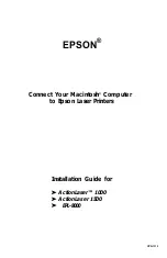
ActionLaser 1000
Brand: Epson Pages: 70
ActionLaser 1000
Brand: Epson Pages: 7
ActionLaser ActionLaser II
Brand: Epson Pages: 11


