2
CONNECTIVITY
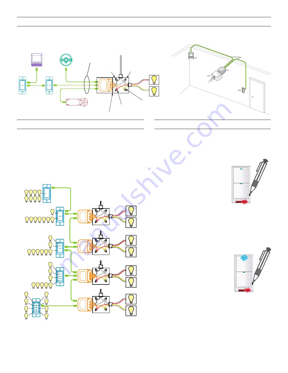
The illustrations below show examples of free-topology wiring. The LMSW switches communicate to all other Digital Lighting
Management devices connected to the low voltage DLM Local Network, regardless of their position on the DLM Local Network.
Line
Voltage
Room
Controller
J-Boxes
Daylight Sensor
Switch
Switch
Corner Mount
Sensor
Ceiling Mount
Sensor
DLM Local Network
Low Voltage
LMRJ Cables
Loads
2
1
Line/Hot
Black wire
Neutral
White wire
Red wire
to Load A (1)
Yellow wire
to Load B (2)
LMRC
102
Room
Controller
J Box
Corner Mount
Occupancy
Sensor
Switch
To
Load/Line
(Class 1 wiring)
DLM Local Network
(low voltage, Class 2)
LMRJ Cables
PLUG N’ GO OPERATION (PNG)
Each load is automatically assigned to a switch button.
• If there are more buttons on a switch than there are loads, the
extra button(s) do nothing and blink when pressed.
• If there are fewer buttons on a switch than there are loads, the
last button controls all remaining loads.
The illustration below shows the Plug n’ Go load binding for each
LMSW switch in a room that has up to 8 loads.
LMSW-108
Loads
Line Voltage
LMRC-102
Room Controller
Dual Relay
J-Box
Line Voltage
J-Box
Line Voltage
J-Box
LMRC-102
Room Controller
Dual Relay
Line Voltage
J-Box
LMSW-103
LMRC-102
Room Controller
Dual Relay
LMRC-102
Room Controller
Dual Relay
1
2
3
4
5
6
7
8
LMSW-102
1
5 6 7 8
2 3 4
LMSW-101
1
5
2
6
3
7
4
8
2
1
6 7 8
3 4 5
LMSW-104
3
4 5 6 7 8
2
1
3
4
2
1
7
8
6
5
Plug n’ Go Load Binding
UNIT ADJUSTMENT - PUSH N’ LEARN (PNL)
Load Selection Procedure
A configuration button allows access to our patented
Push n’ Learn™ technology to change the binding relationship
between switch buttons and loads.
Step 1 Enter Push n’ Learn
1. Using a pointed tool, press and
hold the configuration button for 3
seconds, until the Red LED on the
switch begins to blink.
2. When you release the switch’s
configuration button, the red LED
on other communicating DLM
Local Network devices begins to
blink.
3. The DLM Local Network is now in PnL mode. The Red
LEDs continue to blink until you exit PnL mode.
4. All loads in the room turn OFF after entering PnL. After
one second, one load turns ON. This is Load #1, which
is bound to switch button #1 as part of the Plug n’ Go
factory default setting. The Blue LED will be ON for all
switch buttons and sensors that are bound to this load.
Step 2 Load selection
1. Press and release the
configuration button to step
through the loads connected to
the DLM Local Network. As each
load turns ON note which devices
(switch buttons and sensors) are
showing the blue LED. These
devices are currently bound to the
load that is ON.
2. To unbind a switch button from a load, press the switch
button while its blue LED is ON. The blue LED turns
OFF to indicate the button no longer controls the load
that is currently ON.
3. Pressing the switch button again while the load is
ON rebinds the load to the button and the blue LED
illuminates.
Step 3 Step 3: Exit Push n’ Learn
1. Press and hold the configuration button until the red LED
turns off, approximately 3 seconds.


