Page 11
ATTACHING THE DISPLAY STAND TO YOUR WALL (IF PURCHASED, CONTINUED)
Attaching the Display Stand to a Wall With Wood Studs
NOTE
: Adjust torque on power driver to the “drill” setting.
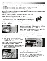
1. Use protective eyewear, power driver, and 3/32” drill bit to drill holes in all the marked keyhole slot
locations. You must hit wall studs in top and bottom keyhole slots on at least one side of the display
stand for proper support.
NOTE
: Adjust torque on power driver to lightest setting and only increase as necessary.
2. Team lift the display stand and place it against your mounting wall aligning keyhole slots with the
prepared holes and anchors.
3. Place a level on the top center of your display stand and make any final adjustments to the leveling
feet (by carefully team tilting the display stand) as necessary.
4. Use power driver, 7/16” socket, (4x) ¼” x 2½” lag bolts (not provided), and (4x) ¼” washers (D)
through keyhole slots and into the drilled holes to secure the stand to your wall.
Attaching the Display Stand to a Solid Concrete Wall
NOTE
: When securing your display stand (A) to a solid concrete wall, you must provide your own
concrete anchors that support the weight ratings specified in “Weight Ratings” on page 5.
Secure your display stand (A) to a solid concrete wall by using a procedure similar to “Securing the
Display Stand to a Wall With Steel Studs or Cinderblocks” on page 10.
INSTALLING AND CONFIGURING THE 10" LEVER LOCK PLATE
NOTE
: One 10” Lever Lock
plate is pre-installed
inside of the display stand.
A Vertical Lever Lock kit is
also avaialbe that includes
an additonal 10” Lever
Lock plate.
For more information,
contact support at
or (866) 977-3901.
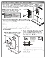
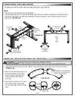
1. Press the clip and lift the same
side of the 10” plate from the display stand column. (
FIGURE G
)
2. Reverse the steps (inserting the 10“ plate tabs on the on the side without the clip first) to re-install the
10” plate to a new location inside the display stand, if desired.
3. Insert securing rivets (J) on the tab beneath the clip of the 10” plate to lock it in place.
TIP
: If necessary, you can remove the securing rivet by pushing its tip end out of the hole with a small
screwdriver, and then pulling by hand at the rivet’s head.
FIGURE G
J
Side
with clip
Side
without clip
Clip
E or F


