


2
IMPORTANT INSTALLATION INFORMATION
To ensure a successful installation and startup of a wireless system, the following steps must be taken by the
installing contractor.
Failure to document all device address and locations may delay completion of startup
and result in additional startup charges.
Key Requirement:
Document
every
Device’s MAC Address (at least the last 4 alphanumeric characters). An
additional MAC address label is included for the installer to use on a floor plan map. The last four characters are
repeated in a larger font, in bold. Keep this document so that the commissioning tech has access at a later date.
SETTING UP A ROOM NETWORK BY PAIRING DEVICES
Pair wireless devices to a room controller to create an individual room network and enable Plug N’ Go operation.
Device pairing can be done by using Push-to-Pair (PtP) mode on the room controller and all other wireless devices, or by using the
DLM Config App.
To pair devices in a network, they must all have the same wireless channel and Network ID. By default the channel is 15 and the
Network ID is 1. Using Push-to-Pair mode, the Network ID for all devices being paired is migrated to a new number, so that only those
device communicate with each other. The channel number will remain at 15.
NOTE:
LMCS-100 software, version 4.7 or later can also be used to pair devices. However, LMCS-100 requires use of an LMBR-650.
Using LMCS, it is possible to change the channel as well as Network ID.
DEVICE PAIRING USING PUSH-TO-PAIR MODE
Push-to-Pair in a room with a single LMRC-611 Room Controller
NOTE:
Once you enter PtP mode on the room controller, a three minute timer begins. If the Config button on any device in the room is
pressed, the timer resets and begins the three minute countdown again. If no Config button is pressed within three minutes, the
room controller will exit PtP mode.
1.
Enter PtP mode
on the room controller.
Press the Config button three times (within three seconds) until the LED on the room
controller flashes green.
2.
Enter PtP mode on the LMSW-605.
Using a pointed tool, press the Config button three times. As with the room controller, the
LED on the switch will flash green.
3.
Pair the LMSW-605.
Press the Config button on the LMSW-605 one more time to pair it to the room controller. The load connected
to the room controller will toggle once (if the load is OFF, it will turn ON; if ON, it will turn OFF) to indicate that pairing was
successful. Also, the LMSW-605’s blinking LED will turn to solid green as another indicator of a successful pairing.
NOTE: If there are any wireless sensors, dimmers, or additional switches in the room, repeat steps 2 and 3
for each of
those devices so that all devices are paired together in the same network. For each device, the load will toggle during step
3 and its config LED will turn solid green.
4.
Exit PtP mode.
From any device, press the Config button 3 times. After a few seconds, the LED on each Room controller, switch
or sensor currently in PtP mode will flash white and reboot, leaving the default network and migrating to the new network. Then,
the LED on the room controller will flash blue and the pairing process finishes.The default Network ID on all devices will change to
a new number, based on the last four digits of the Mac address on the room controller, and now those devices will communicate
only with each other and not any devices which have not been paired.
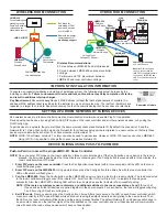
Sensor Params
LMPX-600
LMPC-600
Mode Auto On
Blink On
Load Type Dim
LMRC-611MCC
LMSW-605
Wireless
Scene Switch
Wireless
Sensor and/or
Photosensor
IPv6 Mesh for
networking of DLM
rooms and devices
over 6LoWPAN
Bluetooth low energy
communication for
mobile App support
DLM Configuration App
on a mobile device
LMBR-650
For networking and
managing rooms,
floors, and building
(not needed for
stand-alone rooms)
WIRELESS ROOM CONNECTION
HYBRID ROOM CONNECTION
Ceiling Mount
Occupancy Sensor
LMBC-650
Wireless
Network Bridge
LMBR-650
Border Router
LMSW-605
Wireless
Scene Switch
Line
Voltage
Room
Controller
(LMRC-112)
B
Line Voltage
Switched with
0-10 Volt control
Dimming Ballast
LED Driver, etc.
Load
Examples
(any relay)
A
Switched
etc.
B
Class 1 Dimming
(Class 2 also available)
DLM Configuration App
on a mobile device
Note:
the DLM config app
can only connect with the
LMBC-650 to update firwmare.
You need an LMBR-650 and
LMCS to commision a Hybrid
room.
Sensor Params
LMPX-600
LMPC-600
Mode Auto On
Blink On
Load Type Dim
Distance Recommendations:
30’ max between LMSW-605 and mobile device
60’ max. between LMSW-605 and room controller
or bridge
10’ minimum and 100’ maxmimum between
LMBR-650 and room controller or bridge
Examples of labels
Summary of Contents for LMSW-605-W
Page 5: ...5...


