background image

79

KEOR MULTIPLUG 

600 ВА - 800 ВА

RU

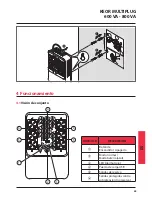
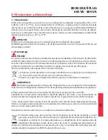
4.1 

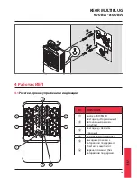
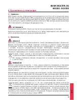
Розетки, органы управления и индикации

2A MAX

5

6

6

5

4

1

2

3

ОПИСАНИЕ

a

Кнопка ВКЛ/ВЫКЛ

b

Светодиод «Нормальный/

Автономный режим» 

(голубой)

c

Светодиод «Авария»
(красный)

d

USB разъем для зарядки

e

Выходные розетки с 

батарейной поддержкой

f

Розетки с защитой от 

перенапряжений (без 

батарейной поддержки)

4  Работа с ИБП

160 мм

Summary of Contents for KEOR MULTIPLUG 600 VA

Page 1: ...Part LE10562AA 02 18 01 GF KEOR MULTIPLUG 600VA 800VA Manuel d installation Installation manual ...

Page 2: ...2 FRANÇAIS 3 ENGLISH 17 ITALIANO 31 DEUTSCH 45 ESPAÑOL 59 PУСCKИЙ 73 FR FR EN KEOR MULTIPLUG 600VA 800VA IT DE ES RU ...

Page 3: ... de fonctionnement et de sécurité 5 3 Installation 7 4 Fonctionnement 9 4 1 Vue d ensemble 9 4 2 Procédure de mise en service 10 4 2 1 Mode normal 10 4 2 2 Démarrage à froid 10 4 3 Arrêt 11 4 4 Voyants et indicateurs d alarme 11 5 Recherche des causes d anomalie 12 6 Stockage et démontage 13 6 1 Stockage 13 6 2 Démontage 13 7 Caractéristiques techniques 14 ...

Page 4: ...llation et utilisation de l équipement ne respectant pas les instructions figurant à cet effet dans le manuel utilisation confiée à un personnel qui n aurait pas lu et intégralement compris le contenu du manuel utilisation non conforme aux standards prévus dans le pays où l équipement est installé modifications apportés à l équipement au logiciel à la logique de fonctionnement à moins qu elles n a...

Page 5: ...leur le débrancher de la prise d alimentation sur secteur Ne pas tenter d ouvrir ou de démonter l onduleur aucune pièce ne peut être changée par l uti lisateur L ouverture de l habillage annule la garantie et expose à des risques d électrocution y compris si l interrupteur d alimentation sur secteur est débranché Dès l instant où le câble non débranchable d alimentation fait office de dispositif d...

Page 6: ...ler à ce qu aucun liquide ou objet étranger ne pénètre à l intérieur de l onduleur L onduleur est prévu pour une installation interne dans un environnement ventilé et contrôlé avec une bande de température entre 0 C 32 F et 40 C 104 F et humidité sans conden sation 95 Ne pas installer l onduleur dans un environnement exposé à des étincelles à de la fumée ou à des gaz dangereux ni dans un environne...

Page 7: ...KEOR MULTIPLUG 600 VA 800 VA 7 FR 3 Installation 3 100 82 3 100 81 3 100 83 3 100 84 100 8 Hours 200 mm 200 mm 200 mm SCANNER LASER PRINTER INKJET PRINTER ...

Page 8: ...8 3 Installation ...

Page 9: ...semble 2A MAX 5 6 6 5 4 1 2 3 RÉF DESCRIPTION a Bouton ON OFF b Voyant Mode normal Mode batterie bleu c Voyant d alarme rouge d Port de recharge USB e Sorties de back up f Sorties protégées contre la surtension sans back up 4 Fonctionnement 160 mm ...

Page 10: ...and l onduleur est éteint Ces prises fournissent une protection uniquement contre les surtensions En cas de coupure de l alimentation sur secteur ces prises ne sont pas alimentées S assurer que l alimentation des charges peut être gérée par l onduleur 5 Appuyer sur la touche ON OFF pour allumer l onduleur et alimenter les charges Les voyants bleu et rouge s allument pendant 3 secondes et dans le m...

Page 11: ...mode normal Clignotement voyant toutes les 3 secondes OFF OFF L onduleur fonctionne en mode batterie avec état batterie 40 100 Clignotement voyant toutes les 3 secondes OFF 1 bip toutes les 10 secondes L onduleur fonctionne en mode batterie avec état batterie 20 40 Clignotement voyant toutes les 2 secondes OFF 1 bip toutes les 2 secondes L onduleur fonctionne en mode batterie avec état batterie 20...

Page 12: ... ou erreur batterie Si le temps de backup reste anormale ment insuffisant au bout de 8 heures de charge des batteries contacter le service d assistance technique LEGRAND L onduleur fonctionne correc tement mais les charges ne sont pas alimentées S assurer que les câbles d alimentation sont correctement branchés Si le problème persiste contacter le ser vice d assistance technique LEGRAND L onduleur...

Page 13: ...ts toxiques Leur élimination comme déchets ordinaires est interdite S informer auprès des autorités compétentes dans le pays où les opérations sont effec tuées pour connaître les procédures à suivre ATTENTION La batterie peut constituer un risque de décharge électrique et de courant élevé de court circuit Lors du fonctionnement sur batteries les prescriptions indiquées dans le chapitre 2 doivent ê...

Page 14: ...A 3 5 A Caractéristiques des sorties Sorties 4 CEE 7 3 avec back up batterie et protection contre surtensions 3 100 81 3 100 82 2 CEE 7 3 avec protection contre surtensions 3 100 81 3 100 82 4 CEE 7 5 avec back up batterie et protection contre surtensions 3 100 83 3 100 84 2 CEE 7 5 avec protection contre surtensions 3 100 83 3 100 84 USB Type A femelle 5 V 1 A Tension nominale 230 V 10 mode batte...

Page 15: ...ants Alarmes Visuelle voyant Sonore avertisseur Protections Contre surcharges surtension et court circuit Fusible entrée remplaçable T5AL250V Courant de retour Température excessive Caractéristiques mécaniques Dimensions L x H x P mm 190 x 89 5 x 296 Poids net kg 5 5 5 Conditions ambiantes Température de fonctionnement 0ºC à 40ºC 32ºF à 104ºF Humidité relative en fonctionnement 95 sans condensatio...

Page 16: ...16 ...

Page 17: ...ght 18 2 Safety and Operating Instructions 19 3 Installation 21 4 Operation 23 4 1 Overview 23 4 2 Start up procedure 24 4 2 1 Normal mode 24 4 2 2 Cold start 24 4 3 Shutdown 25 4 4 LED and Alarm Indicators 25 5 Troubleshooting 26 6 Warehousing and dismantling 27 6 1 Warehousing 27 6 2 Dismantling 27 7 Technical specifications 28 ...

Page 18: ...g from failure to observe the installation instructions and use of the equipment which differs from the specifications in the manual use by personnel who have not read and thoroughly understood the content of the manual use that does not comply with the specific standards used in the country where the equipment is installed modifications made to the equipment software functioning logic unless they...

Page 19: ...el of the UPS The ON OFF button of the UPS does not electrically isolate the internal parts To isolate the UPS unplug it from the mains power socket Do not attempt to open or disassemble the UPS there are no user replaceable parts Opening the case will void the warranty and introduces the risk of electric shock even when the mains plug is disconnected Since the non detachable power supply cable ac...

Page 20: ...m the AC power supply to disable the UPS Do not allow any liquid or any foreign object to enter the UPS The UPS is intended for indoor installation in a ventilated controlled indoor environment with a range of temperature between 0 C 32 F and 40 C 104 F and non condensing humidity 95 Do not install the UPS in locations with sparks smoke and hazardous gas or where there is water and excessive humid...

Page 21: ...21 KEOR MULTIPLUG 600 VA 800 VA EN 3 Installation 3 100 82 3 100 81 3 100 83 3 100 84 100 8 Hours 200 mm 200 mm 200 mm SCANNER LASER PRINTER INKJET PRINTER ...

Page 22: ...22 3 Installation ...

Page 23: ...0 VA EN 4 1 Overview 2A MAX 5 6 6 5 4 1 2 3 ITEM DESCRIPTION a ON OFF button b Normal mode Battery mode LED blue c Alarm LED red d USB recharge port e Back up outlets f Overvoltage protected outlets no back up 4 Operation 160 mm ...

Page 24: ...ervoltage protected sockets they are powered also when the UPS is off These sockets pro vide protection only from overvoltages If the mains power fail these sockets are not powered Ensure that the power of the loads can be managed by the UPS 5 Press the ON OFF button to start up the UPS and power the loads The blue and red leds are lit for 3 seconds along with a 3 seconds long acoustic signal INDI...

Page 25: ... operating in normal mode LED blinking every 3 seconds OFF OFF UPS operating in battery mode with battery status 40 100 LED blinking every 3 seconds OFF 1 beep every 10 seconds UPS operating in battery mode with battery status 20 40 LED blinking every 2 seconds OFF 1 beep every 2 seconds UPS operating in battery mode with battery status 20 Steady OFF Intermittent Overload in normal mode OFF Steady...

Page 26: ...emains unsatisfactory after 8 hours of battery charging contact the LEGRAND Technical Support Service The UPS is working normally but the loads are not powered Check that all power cords are properly connected If the problem persists contact the LEGRAND Technical Support Service The UPS works on battery mode even though the mains power is available The UPS fuse blew up Replace the fuse with a new ...

Page 27: ...in the traditional rubbish is not allowed Apply to the competent agencies in your countries for the proper procedure WARNING A battery may constitute a risk of an electric shock and high short circuit current When working on batteries the prescriptions indicated in chapter 2 are to be adhered to It is important to dismantle the various parts the UPS consists of For these operations Personal Protec...

Page 28: ...s Outlets 4 x CEE 7 3 with battery back up and overvoltage protection 3 100 81 3 100 82 2 x CEE 7 3 with overvoltage protection 3 100 81 3 100 82 4 x CEE 7 5 with battery back up and overvoltage protection 3 100 83 3 100 84 2 x CEE 7 5 with overvoltage protection 3 100 83 3 100 84 USB Type A Female 5 V 1 A Rated voltage 230 V 10 battery mode Rated frequency 50 60 Hz 1 Hz with auto sensing battery ...

Page 29: ...ushbutton and two LEDs Alarms Visual LED Audible buzzer Protections Against overload overvoltage and short circuit Replaceable input fuse T5AL250V Backfeed Overtemperature Mechanical characteristics DimensionsW x H x D mm 190 x 89 5 x 296 Net weight kg 5 5 5 Environmental conditions Operating temperature 0 ºC to 40 ºC 32 ºF to 104 ºF Operating relative humidity 95 non condensing Storage temperatur...

Page 30: ...30 ...

Page 31: ...to e Sicurezza 33 3 Installazione 35 4 Funzionamento 37 4 1 Panoramica 37 4 2 Procedura di accensione 38 4 2 1 Modalità Normale 38 4 2 2 Avviamento a batteria 38 4 3 Spegnimento 39 4 4 Indicatori di allarme e LED 39 5 Risoluzione dei problemi 40 6 Immagazzinamento e smantellamento 41 6 1 Immagazzinamento 41 6 2 Smantellamento 41 7 Specifiche Tecniche 42 ...

Page 32: ...elle istruzioni di installazione e utilizzo dell apparecchiatura diverso da quello pre visto nel manuale utilizzo da parte di personale che non abbia letto e compreso a fondo il contenuto del manuale utilizzo non conforme a normative specifiche in vigore nel Paese in cui il dispositivo viene installato modifiche effettuate all apparecchiatura al software alla logica di funzionamento qualora non au...

Page 33: ...endere l UPS o di collegare qualsiasi carico verificare che l UPS sia collegato a una presa di corrente con adeguata messa a terra Il carico applicato non deve superare quello indicato sull etichetta dell UPS Il pulsante ON OFF dell UPS non isola elettricamente le parti interne Per isolare l UPS scollegar lo dalla presa di alimentazione di rete Non tentare di aprire o smontare l UPS nessuna parte ...

Page 34: ...n un tipo sbagliato Smaltire le batterie usate secondo le istruzioni Questo UPS presenta pericolose tensioni elevate ai collegamenti in ingresso e in uscita Il contat to con tali tensioni potrebbe comportare pericolo di morte In caso di emergenza spegnere immediatamente il dispositivo e scollegare il cavo di alimenta zione dalla presa di alimentazione AC per disabilitare l UPS Evitare che qualsias...

Page 35: ...35 KEOR MULTIPLUG 600 VA 800 VA IT 3 100 82 3 100 81 3 100 83 3 100 84 100 8 Hours 200 mm 200 mm 200 mm SCANNER LASER PRINTER INKJET PRINTER 3 Installazione ...

Page 36: ...36 3 Installazione ...

Page 37: ...mica 2A MAX 5 6 6 5 4 1 2 3 ELEMENTO DESCRIZIONE a Pulsante ON OFF b LED Modalità normale Modalità batteria blu c LED allarme rosso d Porta di ricarica USB e Prese di back up f Prese protette da sovraten sione nessun back up 4 Funzionamento 160 mm ...

Page 38: ...limentate anche quando l UPS è spento Queste prese forniscono protezione solo dalle sovratensioni Se s interrompe l alimentazione di rete queste prese non sono alimentate Assicurarsi che la potenza dei carichi possa essere gestita dall UPS 5 Premere il pulsante ON OFF per avviare l UPS e alimentare i carichi I LED blu e rosso sono illumi nati per 3 secondi insieme ad un segnale acustico di 3 secon...

Page 39: ...o OFF OFF L UPS funziona in modalità normale LED lampeggiante ogni 3 secondi OFF OFF L UPS funziona in modalità batteria con stato batteria 40 100 LED lampeggiante ogni 3 secondi OFF 1 beep ogni 10 secondi L UPS funziona in modalità batteria con stato batteria 20 40 LED lampeggiante ogni 2 secondi OFF 1 beep ogni 2 secondi L UPS funziona in modalità batteria con stato batteria 20 Fisso OFF Intermi...

Page 40: ...rimane insoddisfacente dopo 8 ore di carica delle batterie contattare il Centro Assistenza Tecnica di LEGRAND L UPS funziona normalmente ma i carichi non vengono alimentati Controllare che i cavi di uscita siano correttamente collegati Se il problema persiste contattare il Centro Assistenza Tecnica di LEGRAND L UPS lavora in modalità batteria anche se l alimentazione di rete è disponibile Il fusib...

Page 41: ...i tossici Non smaltire come rifiuto ordinario Contattare gli Enti competenti sul territorio per conoscere la corretta procedura ATTENZIONE Una batteria può costituire un rischio di scossa elettrica e di un elevata corrente di corto circuito Quando si lavora con le batterie è necessario seguire le istruzioni indicate nel capitolo 2 È importante smaltire le varie parti che compongono l UPS Per tali ...

Page 42: ...atteristiche in uscita Uscite 4 x CEE 7 3 con back up a batteria e protezione da sovratensione 3 100 81 3 100 82 2 x CEE 7 3 con protezione da sovratensione 3 100 81 3 100 82 4 x CEE 7 5 con back up a batteria e protezione da sovratensione 3 100 83 3 100 84 2 x CEE 7 5 con protezione da sovratensione 3 100 83 3 100 84 USB Tipo A Femmina 5 V 1 A Tensione nominale 230 V 10 modalità batteria Frequenz...

Page 43: ...e LED Allarmi Visivo LED Sonoro buzzer Protezioni Contro sovraccarico sovratensione e cortocircuiti Fusibile ingresso sostituibile T5AL250V Backfeed Surriscaldamento Caratteristiche meccaniche Dimensioni L x A x P mm 190 x 89 5 x 296 Peso netto kg 5 5 5 Condizioni ambientali Temperatura operativa da 0 ºC a 40 ºC da 32 ºF a 104 ºF Umidità relativa in funzionamento 95 non condensante Temperatura per...

Page 44: ...44 ...

Page 45: ... 1 3 Copyright 46 2 Sicherheits und Bedienungsanleitung 47 3 Installation 49 4 Betrieb 51 4 1 Übersicht 51 4 2 Startup Prozedur 52 4 2 1 Normalbetrieb 52 4 2 2 Kaltstart 52 4 3 Abschalten 53 4 4 LED und Alarmanzeigen 53 5 Problemlösung 54 6 Lagern und entsorgen 55 6 1 Lagern 55 6 2 Entsorgen 55 7 Technische Spezifikationen 56 ...

Page 46: ...nweisungen und Verwendung des Geräts auf eine andere Wei se als im Installationshandbuch angegeben Benutzung durch Personen die den Inhalt der Installationsanleitung nicht gelesen und gründ lich verstanden haben Verwendung die nicht den spezifischen Normen entspricht die in dem Land gelten in dem das Gerät installiert ist Änderungen am Gerät Software Funktionslogik sofern sie nicht vom Hersteller ...

Page 47: ...rennen sie den Netzstecker Versuchen Sie nicht die USV zu öffnen oder zu demontieren Die Anlage enthält keine vom Nutzer austauschbaren Teile Beim Öffnen des Gehäuses erlischt die Garantie Zudem besteht Stromschlaggefahr auch wenn der Netzstecker gezogen ist Da das nicht abnehmbare Stromversorgungskabel als Trennvorrichtung dient muss die Netz steckdose in der Nähe der USV installiert und leicht z...

Page 48: ...ner belüfteten kontrollierten Umgebung mit einer Temperatur von 0 C 32 F bis 40 C 104 F und einer nicht kondensierenden Feuchtigkeit 95 Installieren Sie die USV nicht an Orten wo Funken oder Flammen Rauch oder gefährliches Gas durch andere Geräte entstehen können oder in übermäßig feuchten Räumen Staubige korro sive und salzige Umgebungen können die USV beschädigen Schließen sie den USV Eingang ni...

Page 49: ...49 KEOR MULTIPLUG 600 VA 800 VA DE 3 Installation 3 100 82 3 100 81 3 100 83 3 100 84 100 8 Hours 200 mm 200 mm 200 mm SCANNER LASER PRINTER INKJET PRINTER LASERDRUCKER TINTENSTRAHLDRUCKER ...

Page 50: ...50 3 Installation ...

Page 51: ... 160 mm 4 1 Übersicht 2A MAX 5 6 6 5 4 1 2 3 ITEM DESCRIPTION a ON OFF Taste b Normaler Modus Batterie Modus LED blau c Alarm LED rot d USB Aufladebuchse e Backup Ausgänge f Gegen Überspannungen geschützte Ausgänge ohne Backup 4 Betrieb ...

Page 52: ... bei ausgeschalteter USV versorgt Diese Buchsen bieten nur Schutz vor Überspannungen Bei Ausfall werden diese Buchsen nicht versorgt Stellen Sie sicher dass die USV zur Stromversorgung der Verbraucher geeignet ist 5 Drücken Sie die ON OFF Taste um die USV zu starten und die Verbraucher mit Strom zu versor gen Die blaue und rote LED leuchten für 3 Sekunden auf und ein 3 Sekunden langes akustisches ...

Page 53: ...F Die USV arbeitet im Normalbetrieb LED blinkt 3 Sekunden lang OFF OFF USV Betrieb im Batteriebetrieb mit Batteriestatus 40 100 LED blinkt 3 Sekunden lang OFF 1 Piepton alle 10 Sekunden USV Betrieb im Batteriebetrieb mit Batteriestatus 20 40 LED blinkt 2 Sekunden lang OFF 1 Piepton alle 2 Sekunden USV Betrieb im Batteriebetrieb mit Batteriestatus 20 Fest leuchtend OFF Intermittierend Überlast im N...

Page 54: ...den Akkuladung unbefriedigend bleibt wenden Sie sich an den technischen Kundendienst von LEGRAND Der USV Betrieb ist normal aber die Verbraucher werden nicht mit Strom versorgt Kontrollieren ob alle Stromkabel richtig angeschlossen sind Wenn das Problem weiterhin besteht wenden Sie sich an den technischen Kundendienst von LEGRAND Die USV arbeitet im Batteriebetrieb obwohl die Netzspannung vorhande...

Page 55: ...müll ist nicht erlaubt Fragen Sie die zuständigen Stellen Ihres Lands um das Gerät ordnungsgemäß zu ent sorgen WARNUNG Die Batterie ist wegen Stromschlaggefahr und dem hohen Kurzschlussstrom gefährlich Wenn an den Batterien gearbeitet werden muss sind die in Kapitel 2 angegebenenVorschriften zu beachten Es ist wichtig die verschiedenenTeile aus denen die USV besteht zu zerlegen Dafür muss persönli...

Page 56: ...rom 2 8 A 3 5 A Ausgangseigenschaften Ausgänge 4 x CEE 7 3 mit Batterie Backup und Überspannungsschutz 3 100 81 3 100 82 2 x CEE 7 3 mit Überspannungsschutz 3 100 81 3 100 82 4 x CEE 7 5 mit Batterie Backup und Überspannungsschutz 3 100 83 3 100 84 2 x CEE 7 5 mit Überspannungsschutz 3 100 83 3 100 84 USB Typ A Buchse 5 V 1 A Nennausgangsspannung 230 V 10 Batteriemodus Nennausgangsfrequenz 50 60 H...

Page 57: ...e und zwei LEDs Alarme Visuell LED akustisch Summer Schutzvorrichtungen Gegen Überlast Überspannung und Kurzschluss Austauschbare Sicherung T5AL250V Backfeed Übertemperatur Mechanische Eigenschaften AbmessungenBxHxT mm 190 x 89 5 x 296 Nettogewicht kg 5 5 5 Umgebungsbedingungen Betriebstemperatur 0 ºC to 40 ºC 32 ºF to 104 ºF Relative Feuchtigkeit bei Betrieb 95 nicht kondensierend Lagerungstemper...

Page 58: ...58 ...

Page 59: ... de seguridad y funcionamiento 61 3 Instalación 63 4 Funcionamiento 65 4 1 Visión de conjunto 65 4 2 Procedimiento de arranque 66 4 2 1 Modo normal 66 4 2 2 Arranque frío 66 4 3 Apagado 67 4 4 Indicadores LEDs y alarmas 67 5 Búsqueda de averías 68 6 Almacenaje y desmontaje 69 6 1 Almacenaje 69 6 2 Desmontaje 69 7 Especificaciones técnicas 70 ...

Page 60: ...cta o indirecta derivada de incumplimiento de las instrucciones de instalación y uso del equipo sin seguir las especificacio nes del manual uso por personal que no ha leído y comprendido completamente el contenido del manual uso no conforme a los estándares específicos vigentes en el país de instalación del equipo modificaciones aportadas al equipo software lógica de funcionamiento sin la autoriza...

Page 61: ...FF del SAI no aísla eléctricamente las partes internas Desconectar el SAI del enchufe de corriente para aislarlo No intentar abrir o desmontar el SAI no contiene partes que se puedan sustituir por el usuario Abrir la carcasa anula la garantía y comporta el riesgo de choque eléctrico incluso con la clavija desconectada El cable de tensión de alimentación no desmontable sirve de dispositivo de separ...

Page 62: ...tar el cable de corriente de la toma CA para deshabilitar el SAI No permitir que líquidos o cuerpos extraños puedan entrar en el SAI El SAI se contempla para la instalación en el interior en un entorno ventilado y controlado con un rango de temperaturas comprendidas entre 0 C 32 F y 40 C 104 F y sin humedad de condensación 95 No instalar el SAI en lugares donde chispas humo y gas peligroso o en ca...

Page 63: ...63 KEOR MULTIPLUG 600 VA 800 VA ES 3 100 82 3 100 81 3 100 83 3 100 84 100 8 Hours 200 mm 200 mm 200 mm SCANNER LASER PRINTER INKJET PRINTER 3 Instalación ...

Page 64: ...64 3 Instalación ...

Page 65: ...conjunto 2A MAX 5 6 6 5 4 1 2 3 ARTÍCULO DESCRIPCIÓN a Botón de Encendido Apagado b Modo normal Modo batería azul c LED Alarma roja d Puerto de carga USB e Salidas de reserva f Salidas protegidas contra sobretensión no reserva 4 Funcionamiento 160 mm ...

Page 66: ...n se alimentan también con el SAI apagado Dichas tomas proporcionan protección solamente contra sobretensiones Si la tensión de la red falla estas tomas no están alimentadas Asegurarse de que la alimentación de las cargas pueda gestionarse con el SAI 5 Presionar el pulsador de ON OFF para encender el SAI y alimentar las cargas Los LEDs azul y rojo se enciende 3 segundos al mismo tiempo que una señ...

Page 67: ...I Fijo OFF OFF El SAI funciona en el modo normal Parpadeo del LED cada 3 segundos OFF OFF El SAI funciona en el modo batería con estado batería 40 100 Parpadeo del LED cada 3 segundos OFF 1 tono cada 10 segundos El SAI funciona en el modo batería con estado batería 20 40 Parpadeo del LED cada 2 segundos OFF 1 tono cada 2 segundos El SAI funciona en el modo batería con estado batería 20 Fijo OFF In...

Page 68: ...ras de carga de las baterías ponerse en contacto con el Servicio de asistencia técnica LEGRAND El SAI funciona normalmente pero las cargas no están alimentadas Controlar que todos los cables de salida estén conectados correctamente Si el problema persiste ponerse en contacto con el Servicio de asistencia técnica LEGRAND El SAI funciona en el modo batería a pesar de haber potencia disponible en la ...

Page 69: ... un lugar destinado a la recuperación de residuos tóxi cos No se permite la eliminación en los residuos domésticos Dirigirse a las agencias competentes del país para los procedimientos adecuados ADVERTENCIA Una batería puede presentar un riesgo de choque eléctrico y una corriente de cortocircuito ele vada Cuando se trabaja en las baterías se han de respetar las prescripciones indicadas en el capít...

Page 70: ...aracterísticas de salida Conexión 4 x CEE 7 3 con reserva bateria y protección contra sobretensión 3 100 81 3 100 82 2 x CEE 7 3 con protección contra sobretensión 3 100 81 3 100 82 4 x CEE 7 5 con reserva batería y protección contra sobretensión 3 100 83 3 100 84 2 x CEE 7 5 con protección contra sobretensión 3 100 83 3 100 84 USB Hembra tipo A 5 V 1 A Tensión nominal 230 V 10 modo batería Frecue...

Page 71: ... dos LEDs Alarmas Visual LED Acústica avisador Protecciones Contra sobrecarga sobretensión y cortocircuito Fusible de entrada sustituible T5AL250V Backfeed Sobretemperatura Características mecánicas Medidas A x A x P mm 190 x 89 5 x 296 Peso neto kg 5 5 5 Condiciones ambientales Temperatura de funcionamiento 0 ºC to 40 ºC 32 ºF to 104 ºF Humedad relativa de funcionamiento 95 no condensados Tempera...

Page 72: ...72 ...

Page 73: ...ти и правила работы с изделием 75 3 Монтаж 77 4 Работа с ИБП 79 4 1 Розетки органы управления и индикации 79 4 2 Процедура пуска 80 4 2 1 Нормальный режим 80 4 2 2 Холодный старт 80 4 3 Выключение 81 4 4 Светодиоды и звуковая сигнализация 81 5 Устранение неисправностей 82 6 Хранение и утилизация 83 6 1 Хранение 83 6 2 Демонтаж 83 7 Технические характеристики 84 ...

Page 74: ...следствие несоблюдения указаний по монтажу и использования оборудования характеристики которого отличаются от указанных в настоящем Руководстве эксплуатации оборудования персоналом не изучившим настоящее Руководство эксплуатации с нарушением нормативных документов страны в которой установлено оборудование внесения изменений в оборудование программное обеспечение и логику работы которые не были раз...

Page 75: ...ртной табличке на задней стороне изделия Кнопка ВКЛ ОТКЛ на ИБП не имеет гальванической развязки с внутренними элементами изделия Для изоляции ИБП необходимо отсоединить его от электросети вытащив шнур питания из розетки Категорически запрещается вскрывать корпус и разбирать ИБП он не содержит деталей заменяемых пользователем Вскрытие корпуса влечет за собой отмену гарантии и может привести к пора...

Page 76: ...В случае опасности немедленно выключите ИБП кнопкой и вытащите шнур питания из розетки электросети Не допускайте попадания внутрь ИБП жидкостей и посторонних предметов ИБП предназначен для установки в вентилируемом помещении с контролируемым микроклиматом при температуре 0 40 C и относительной влажности воздуха 95 Запрещается устанавливать ИБП в местах где возможно появление искр и дыма взрывоопас...

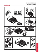
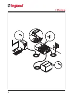
Page 77: ...77 KEOR MULTIPLUG 600 ВА 800 ВА RU 3 Монтаж 3 100 82 3 100 81 3 100 83 3 100 84 100 8 часов 200 мм 200 мм 200 мм Сканер Лазерный принтер Струйный принтер ...

Page 78: ...78 3 Монтаж ...

Page 79: ... 2A MAX 5 6 6 5 4 1 2 3 ОПИСАНИЕ a Кнопка ВКЛ ВЫКЛ b Светодиод Нормальный Автономный режим голубой c Светодиод Авария красный d USB разъем для зарядки e Выходные розетки с батарейной поддержкой f Розетки с защитой от перенапряжений без батарейной поддержки 4 Работа с ИБП 160 мм ...

Page 80: ...ен Эти розетки имеют защиту от перенапряжений При исчезновении напряжения электросети они не будут запитаны Обеспечьте чтобы нагрузки питание которых нуждается в защите были подключены к розеткам с батарейной поддержкой 5 Нажмите кнопку ВКЛ ВЫКЛ чтобы включить ИБП и подать питание на нагрузки Голубой и красный светодиоды загорятся на 3 секунды в течение которых также будет подаваться непрерывный з...

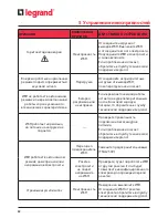
Page 81: ... свечение ОТКЛ ОТКЛ Работает в нормальном режиме Мигает каждые 3 с ОТКЛ ОТКЛ Работает в нормальном режиме батарея заряжена на 40 100 Мигает каждые 3 с ОТКЛ 1 сигнал каждые 10 с Работает в нормальном режиме батарея заряжена на 20 40 Мигает каждые 2 с ОТКЛ 1 сигнал каждые 2 с Работает в нормальном режиме батарея заряжена на 20 Ровное свечение ОТКЛ Прерывистый сигнал Перегрузка в нормальном режиме ОТ...

Page 82: ...или неисправна Если время автономной работы остается неудовлетворительным после 8 часовой зарядки батареи то обратитесь в службу технической поддержки Legrand ИБП работает нормально но питание на нагрузки не подается Проверьте правильность подключения всех шнуров питания Если проблема не исчезает обратитесь в службу технической поддержки Legrand ИБП работает в автономном режиме даже при наличии на...

Page 83: ...ающуюся утилизацией опасных отходов Запрещается выбрасывать их вместе с бытовым мусором По поводу утилизации батарей обращайтесь в соответствующие организации в своей стране ВНИМАНИЕ Батареи представляют опасность с точки зрения короткого замыкания и поражения электрическим током При обращении с батареями строго следуйте указаниям раздела 2 Перед утилизацией ИБП подлежит разборке Эти операции выпо...

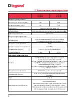
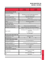
Page 84: ...5 Гц с автообнаружением Номинальный ток 2 8 А 3 5 A Выходные характеристики Розетки 4хCEE7 3сбатарейнойподдержкойизащитой отперенапряжений 310081 310082 2хCEE7 3сзащитойотперенапряжений 310081 310082 4хCEE7 5сбатарейнойподдержкойизащитойот перенапряжений 310083 310084 2хCEE7 5сзащитойотперенапряжений 310083 310084 ГнездоUSBTypeA 5В 1A Номинальное напряжение 230 В 10 в автономном режиме Номинальная...

Page 85: ...ва светодиода Аварийная сигнализация Визуальная светодиоды звуковая зуммер Виды защиты От перегрузки перенапряжения и короткого замыкания с помощью сменного входного предохранителя T5AL250V От обратного тока От перегрева Механические характеристики РазмерыШ x В x Г мм 190 x 89 5 x 296 Масса нетто кг 5 5 5 Условия окружающей среды Рабочая температура от 0 ºC до 40 ºC Рабочая относительная влажность...

Page 86: ...86 ...

Page 87: ...87 ...

Page 88: ...roit de modifier à tout moment le contenu de cet imprimé et de communiquer sous n importe quelle forme et modalité les changements apportés LEGRAND Pro and Consumer Service BP 30076 87002 LIMOGES CEDEX FRANCE www legrand com ...

Reviews: