Installation Instructions
DMA Series
5
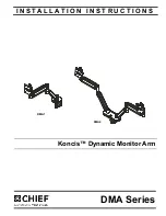
TOOLS REQUIRED FOR INSTALLATION
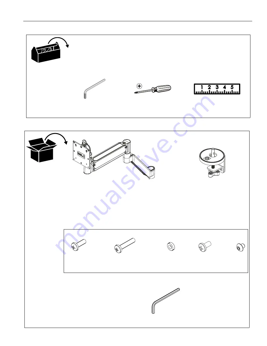
PARTS
#2
5/32” (included)
A (1)
[Arm assembly]
(DMA1 shown)
C (4/8)*
M4x10mm
D (4/8)*
M4x20mm
E (4/8)*
M10x5.3x10
5/32"
H (1)
F (1/2)*
#10-32-3/8”
* - (DMA1/DMA2)
G (1/2)*
M4x4mm
Hardware bag
B (1)
[Base assembly]
(DMA1 shown)