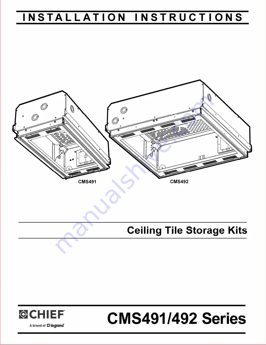
Ceiling Tile Storage Kits
I N S T A L L A T I O N I N S T R U C T I O N S
CMS491/492 Series
Page 1: ...Ceiling Tile Storage Kits I N S T A L L A T I O N I N S T R U C T I O N S CMS491 492 Series...
Page 2: ...CMS492 Series component shelf may not exceed 25 lbs 22 kg per shelf all components attached to the extension column CMS491C CMS492C models only does not exceed 50 lbs 22 kg WARNING Never operate this...
Page 3: ...M SHELF SPACE 7 58 192 4 AVAILABLE STORAGE HEIGHT SECTION B B 2 59 65 9 PIPE DROP CENTER 13 63 346 1 PIPE DROP TRAVEL 5 02 127 5 PIPE DROP MIN CENTER B B 1 REMOVABLE SHELF INCLUDED 2 SPACES TOTAL AVAI...
Page 4: ...PIPE DROP MIN CENTER 9 40 238 9 PIPE DROP TRAVEL 5 02 127 5 13 63 346 1 PIPE DROP TRAVEL B B 1 REMOVABLE SHELF INCLUDED 2 SPACES TOTAL AVAILABLE ELECTRICAL INSTALL PLATE SPACE FOR A SINGLE GANG OUTLE...
Page 5: ...and A la main Martillo Hammer Martelo Martello Hamer Marteau Llave de seguridad Sicherheitsschlussel Chave de seguranca Chiave di sicurezza Veiligheidssleutel Cle de securite Punto de enfoque del proy...
Page 6: ...el number 10 24 x 1 4 Button Head Security Screw L Cable Lock Wire Vice E 10 24 x 1 4 Pan Head Machine Screw 2x 4x 4x 4x 4x Chief CMS1RU Shelf Rack Adaptor 4x D Install Box CMS492 shown A Component Sh...
Page 7: ...solid concrete with a minimum thickness of 1 75 44 5mm or greater Installation into hollow concrete block mortar or concrete that exhibits cracking spalling or other defects may result in failure of a...
Page 8: ...e 4 2 Route end of cable N through eye lag J and then through cable loop See Figure 4 Repeat for 3 remaining support locations 3 5 32 J N 3 2 1 Figure 4 Figure 5 Installing Electrical Box and Outlets...
Page 9: ...m projector mount plate 2 Remove attached electrical plate from underside of projector mount plate Save nuts for reinstall 1 Figure 9 Figure 10 Figure 12 Figure 11 Cleat adjustment for various tile he...
Page 10: ...lead to serious injury or death CAUTION Failure to properly tension cables N may result in damage to ceiling tile framework Figure 17 Figure 19 Figure 18 Ceiling Frame Figure 20 Remove adjacent ceilin...
Page 11: ...installing the Listed accessories CMS441 and CMS442 into Models CMS491 and CMS492 respectively Projector Mount Plate and Extension Column Installation OPTIONAL Install the electrical outlets as outli...
Page 12: ...rt tightening firmly against column B OPTIONAL Install one 10 24 x 1 4 button head security screw E through security spinner F into column support tightening firmly against column Move the mount plate...
Page 13: ...Installation Instructions CMS491 492 13...
Page 14: ...Installation Instructions CMS491 492 14...
Page 15: ...Installation Instructions CMS491 492 15...
Page 16: ...18 Europe A Franklinstraat 14 6003 DK Weert Netherlands P 31 0 495 580 852 F 31 0 495 580 845 Asia Pacific A Office No 918 on 9 F Shatin Galleria 18 24 Shan Mei Street Fotan Shatin Hong Kong P 852 214...