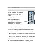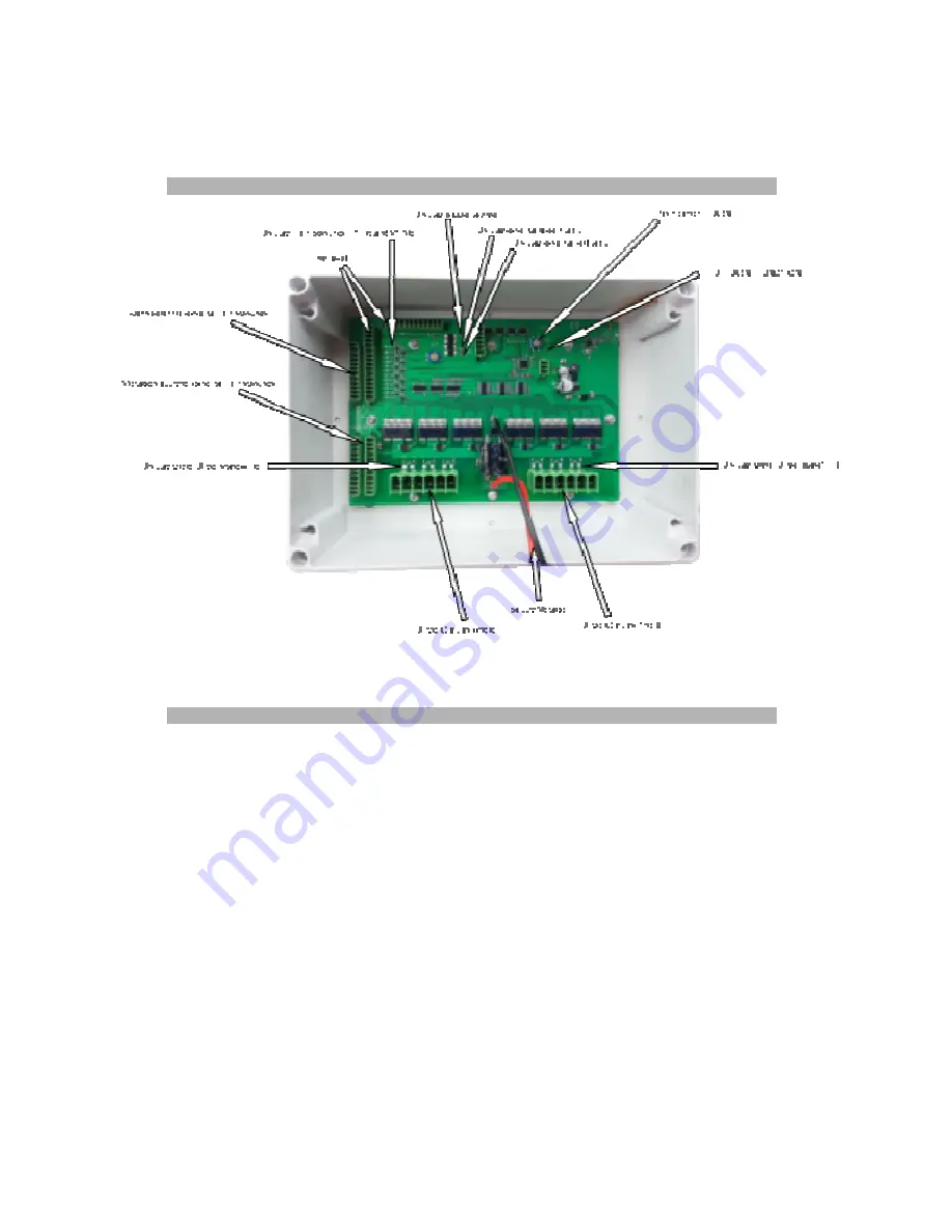
3.0 TRANSCEIVER (also referred to as receiver)
3.1 Normal Operation
Immediately after connection of the supply voltage the receiver is in its normal operation mode (No push button may be
pressed while starting this mode). In order to save battery capacity, the supply voltage should be taken off, when the
receiver is not used.
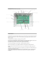
The activated functions are displayed by the dedicated LEDs on the PCB.
If the function unlock was started from the handheld transmitter, the motor driver outputs “E” will stay active as long as
the appropriated limit switch signalises to be closed by the display limit switch LEDs (E1 to E6).
The number of usable motor driver outputs and limit switch inputs is factory predifined.
The lock function is analogous to the unlock funtion. Only LEDs and outputs are labeled “V”
Motor driver outputs giving the positiv voltage are displayed by the LEDs placed above (display motor driver)
All start up features for motor driver and the reaction when motors are blocked are factory settings and may not be
changed.
The reception of correctly received radio signal packet is displayed by a short flash of the LED „LEARN/FUNCTION” in
case of good battery voltage of the receiver.
If ever this battery voltage drops below an allowed level, the above LED will flash two times for each radio reception.
In this case there are another 5 function cycles (lock/unlock) that remain, before the system will stop all further
manipulations.


