

v.7.18.19
Ledra Brands Inc.
www.LedraBrands.com
In a continuing effort to offer the best product possible we reserve the right to change, without notice, specifications or materials that in our opinion will not alter the function of the product.
15774 Gateway Circle Tustin, CA 92780
P 714.259.9959 F 714.259.9969
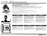
STEP 1C - RETROFIT:
NEW CONSTRUCTION MOUNTING PLATE
(NOT FOR USE WITH RETROFIT)
RETROFIT VERSION
HOLE CUTOUT 4-1/4
"
SQUARE
Carefully remove bezel from LED Module Assembly. Use fingers to pull bezel away from LED
Module Assembly. For lens option, use suction cup (provided) to remove bezel. Sharp or flat
objects not recommended as they can damage the bezel or snap locks.
Connect the (2) sets of quick disconnect from driver compartment to LED Module Assembly.
Insert the LED Module Assembly through the ceiling cutout and aim light to desired position.
Hand tighten the Phillips head fastening screws to secure the LED Module Assembly to the
New Construction Mounting Plate. Ensure the LED Module Assembly is securely fastened
against the ceiling but has not recessed into soft ceiling tiles due to over tightening.
Energize circuit and test for proper operation.
Adjust hot Aiming Screw to fine tune light beam direction using Phillips screwdriver. For fine
tuning rotational adjustment, loosen rotation lock screw, reposition as desired, and secure
rotation lock screw.
Carefully insert bezel (or lens) into LED Module Assembly. Press firmly until it snaps into place.
Follow compatible control instructions for CCT and light intensity control. Controls not included.
(provided by others)
NU Series
Tunable White
CCT
Light Intensity
120/277VAC
50/60Hz INPUT
0-10V INPUT #2
0-10V INPUT #1
STANDARD 0-10V SWITCHES
NU Series
Tunable White
Integrated
Antenna
COMPATIBLE WIRELESS SWITCHES
CASAMBI™ APP (IOS & Android)
Wireless Commissioning,
CCT & Light Intensity Control
CCT & Light Intensity Control
120/277VAC
50/60Hz INPUT
“CAS” CASAMBI CONTROLS
STEP 2 - FIXTURE INSTALLATION:
STEP 3
STEP 4
STEP 5
STEP 6
STEP 7
STEP 8
STEP 9
WIRING DIAGRAMS
INSTRUCTIONS FOR USE
De-energize circuit before installation.
Ensure placement of fixture will accommodate New Construction Mounting Plate and LED
Module Assembly. Adjust bar hangers to size and secure New Construction Mounting Plate
as required using integral nails and screws or suspend in T- Bar grid ceiling. Ensure the
fixture is properly supported and attached to building. Refer to product cut sheet and cut
hole into ceiling as required. Feed building flexible electrical conduit through ceiling cutout
and ensure enough conduit length for future serviceability. Open driver compartment and
use knockout to connect building electrical using appropriate hardware. (Hardware not
provided). Connect line, neutral, and ground wires to building electrical supply. Close driver
compartment. For future servicing, do not attach to driver to any structure.
STEP 1A- EXISTING CEILING:
STEP 1B NEW CONSTRUCTION:
Installation Screw
Installation Screw
Rotation Lock Screw
Hot Aiming Screw
“DIM10Z” HARDWIRED 0-10V CONTROL
New Construction Mounting Plate not used. Ensure area above finished ceiling will
accommodate placement of fixture and driver compartment. Refer to product cut sheet
and cut hole into ceiling as required. Feed building flexible electrical conduit through
ceiling cutout and ensure enough conduit length for future serviceability. Open driver
compartment and use knockout to connect building electrical using appropriate hardware.
(Hardware not provided). Connect line, neutral, and ground wires to building electrical
supply. Close driver compartment. For future servicing, do not attach to driver to any
structure.