background image

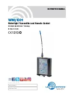
WM/E01

LECTROSONICS, INC.

4

Servo Bias Input

The voltage and current requirements of the wide 

variety of electret microphones used in professional 

applications has caused confusion and compromises 

in the wiring needed for wireless transmitters. To 

address this problem, the unique Servo Bias input 

circuit provides an automatically regulated voltage 

over a very wide range of current for compatibility 

with all microphones.

Digital Hybrid Wireless

®

 Technology

All wireless links suffer from channel noise to some 

degree, and all wireless microphone systems seek to 

minimize the impact of that noise on the desired signal. 

Conventional analog systems use compandors for 

enhanced dynamic range, at the cost of subtle artifacts 

(typically “pumping” and “breathing”). Wholly digital 

systems defeat the noise by sending the audio informa-

tion in digital form, at the cost of some combination of 

power, bandwidth and resistance to interference.
Digital Hybrid systems overcome channel noise in 

a dramatically new way, digitally encoding the audio 

in the transmitter and decoding it in the receiver, yet 

still sending the encoded information via an analog 

FM wireless link. This proprietary algorithm is not a 

digital implementation of an analog compandor but 

a technique that can be accomplished only in the 

digital domain, even though the inputs and outputs 

are analog.
Because it uses an analog FM link, the Digital Hybrid 

system enjoys all the benefits of conventional FM 

wireless systems and it does away with the analog 

compandor and its artifacts.

General Technical Description

No Pre-Emphasis/De-Emphasis

The Digital Hybrid design results in a signal-to-noise 

ratio high enough to preclude the need for conventional 

pre-emphasis (HF boost) in the transmitter and de-

emphasis (HF roll off) in the receiver. This eliminates 

the potential for distortion of signals with abundant 

high-frequency information.

Low Frequency Roll-Off

The low frequency roll-off can be set for a 3 dB down 

point at 35, 50, 70, 100, 120 and 150 Hz to control 

subsonic and very low frequency audio content in 

the audio. The actual roll-off frequency will vary slightly 

depending upon the low frequency response of the 

microphone.
Excessive low frequency content can drive the 

transmitter into limiting, or in the case of high output 

sound systems, it can even cause damage to loud-

speaker systems. The roll-off is normally adjusted by 

ear while listening as the system is operating.

Input Limiter

A DSP-controlled analog audio limiter is employed 

before the A-D converter. The limiter has a range of 

more than 30 dB for excellent overload protection. A 

dual release envelope makes the limiter acoustically 

transparent while maintaining low distortion. It can be 

thought of as two limiters in series, a fast attack and 

release limiter followed by a slow attack and release 

limiter. The limiter recovers quickly from brief tran-

sients, with no audible side effects, and also recov-

ers slowly from sustained high levels to keep audio 

distortion low while preserving short term dynamics.

Variable 1.8 - 4v

+6V

+5V

5V

Regulator

Summary of Contents for WM/E01

Page 1: ...tertight Transmitter and Remote Control With Digital Hybrid Wireless Technology INSTRUCTION MANUAL Rio Rancho NM USA www lectrosonics com Fill in for your records Serial Number Purchase Date US Patent 7 225 135 ...

Page 2: ...WM E01 LECTROSONICS INC 2 ...

Page 3: ...transmitter can be operated from alkaline lithium or rechargeable NiMH batteries The Digital Hybrid Wireless design US Patent 7 225 135 combines 24 bit digital audio with analog FM resulting in a system that has the same operating range as analog systems the same spectral effi ciency as analog systems the same long battery life as analog systems plus the excellent audio fidelity typical of pure di...

Page 4: ...fits of conventional FM wireless systems and it does away with the analog compandor and its artifacts General Technical Description No Pre Emphasis De Emphasis The Digital Hybrid design results in a signal to noise ratio high enough to preclude the need for conventional pre emphasis HF boost in the transmitter and de emphasis HF roll off in the receiver This eliminates the potential for distortion...

Page 5: ...gulated battery voltages to operate various circuit stages with maxi mum efficiency With the variety of alkaline lithium and rechargeable NiMH batteries available today in the AA format there are many choices to maximize operating time or minimize cost as needed for any application The firmware remembers the settings when the batteries are exhausted After new batteries are installed a quick press ...

Page 6: ...djustment is critical to ensure the best audio quality Two red green LEDs will glow to accurately indicate modulation levels The input circuitry includes a wide range DSP controlled limiter to prevent distortion during high peak levels It is important to set the gain audio level high enough to achieve full modulation during louder peaks in the audio The DSP controlled limiter can handle peaks over...

Page 7: ... begins to blink red there are only a few minutes remaining The exact point at which the LED turns red will vary with battery brand and condition temperature and current drain The LED is simply a reminder intended to catch your attention not an exact indicator of remaining time 1 6 1 4 1 2 1 0 8 2 4 6 8 Hours Voltage Varies Green Red Blink DO NOT COVER VENT HOLES Battery polarity is marked on the ...

Page 8: ...he adjustments are complete press both the AUDIO and FREQ buttons briefly to save the settings and turn the unit off Compatibility Bias Voltage phantom power and LCD Backlight Four different setup screens are accessed in a setup mode that is accessed with a special button se quence Compatibility Mode Bias Voltage phantom power LCD Backlight Settings Hold the UP arrow button and simultaneously pres...

Page 9: ... firmware is written this way because the battery caps make contact with the battery before the cap is seated and the fact that there are two separate battery caps to tighten This allows both batteries to be installed and the caps tightened before power is restored It also makes turning the unit back on easier when wearing gloves since the buttons do not need to the held in Compatibility Mode In a...

Page 10: ...his gain adjustment matches the transmitter gain with the microphone s output level the user s voice level and the position of the microphone It is desirable to to set the gain so that some limiting occurs on louder peaks The limiter is very transpar ent and its effect is not audible until the system is close to overload In other words don t be shy about turning up the gain In fact it is a good id...

Page 11: ...een exposed to mois ture or perspiration follow the instructions below to minimize the risk of corrosion DRY THE UNIT BEFORE REMOVING THE MICRO PHONE CONNECTOR OR BATTERY CAPS If the transmitter has been exposed to salt water rinse it with fresh water and then dry it thoroughly with a clean paper towel or cloth Dry the exterior of the transmitter with a clean paper towel or cloth Remove all moistu...

Page 12: ... Transmitter and receiver not on same frequency Check switches display on transmitter and receiver 5 Transmitter and receiver not on same frequency block 6 Operating range is too great 7 Defective transmitter antenna NO SOUND OR LOW SOUND LEVEL RECEIVER INDICATES PROPER AUDIO MODULATION 1 Receiver output level set too low 2 Receiver output disconnected or cable defective or mis wired 3 Sound syste...

Page 13: ...em Try a different operating frequency Loc APPEARS IN DISPLAY WHEN ANY BUTTON IS PRESSED 1 Control Panel is locked See Operating Instructions Locking and Unlocking the Control Panel Hold APPEARS IN DISPLAY WHEN ARROW BUTTONS ARE PRESSED 1 Reminder that it is necessary to hold down the AUDIO or FREQ button to make adjustments to the audio gain or frequency settings PLL APPEARS IN DISPLAY 1 Indicati...

Page 14: ...ing loaded included with transmitter WPMC 3 Watertight connector kit 3 piece to terminate lava liere microphones for use with the WM transmitter WPMC 10 Watertight connector kit 10 piece to terminate lava liere microphones for use with the WM transmitter Battery Cap TBA Battery Cap Lanyard TBA O ring for Battery Cap TBA ...

Page 15: ...ge Bias voltages Selectable 2V 4V and Off Gain control range 44 dB panel mounted membrane switches Modulation indicators Dual bicolor LEDs indicate modulation of 20 10 0 10 dB referenced to full modulation Controls Control panel with LCD and four membrane switches Low frequency roll off Adjustable from 35 to 150 Hz 30 100 1kHz 10k 20k 6 3 0dB 3 6 9 12 Line in Mic in 150 Hz Roll off Mic in 35 Hz Ro...

Page 16: ... TTE Directive 1999 5 EC The WM E01 may be operated in AT BE BG CH CY CZ DE DK EE FI FR GR HU IE IS LT LU LV MT NL NO PT RO SE SI SK UK The use of the WM E01 requires a license and is subject to national restrictions on frequency selection and channel spacing ...

Page 17: ...nty repairs Returning Units for Repair For timely service please follow the steps below A DO NOT return equipment to the factory for repair without first contacting us by email or by phone We need to know the nature of the problem the model number and the serial number of the equipment We also need a phone number where you can be reached 8 A M to 4 P M U S Mountain Standard Time B After receiving ...

Page 18: ...WM E01 LECTROSONICS INC 18 ...

Page 19: ...Watertight Transmitter Rio Rancho NM 19 ...

Page 20: ...rosonics Inc will pay for the cost of returning your equipment to you This warranty applies only to items returned to Lectrosonics Inc or an authorized dealer shipping costs prepaid within one year from the date of purchase This Limited Warranty is governed by the laws of the State of New Mexico It states the entire liablility of Lectrosonics Inc and the entire remedy of the purchaser for any brea...

Reviews: