background image

HH/E01

LECTROSONICS, INC.

10

About Setting Audio Gain

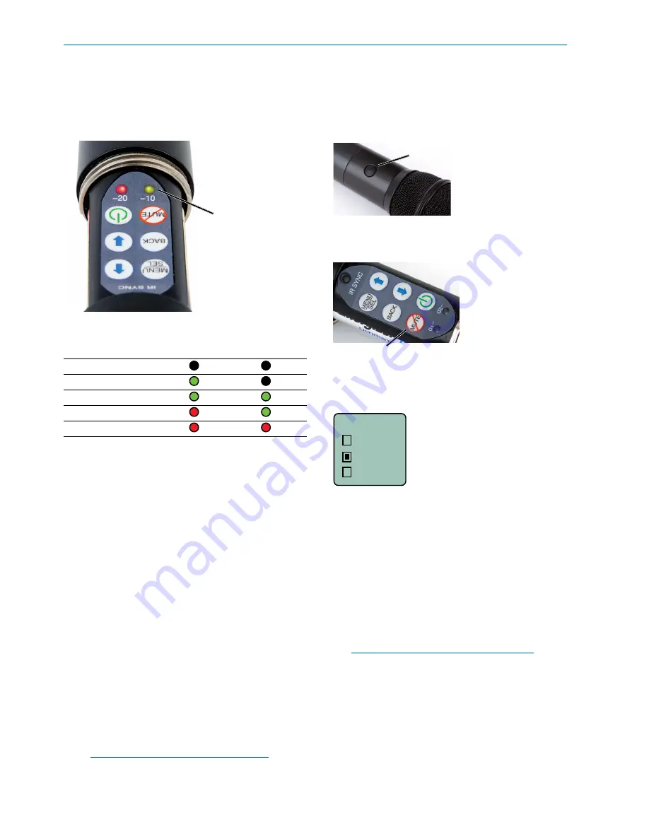
The two bicolor Modulation LEDs (located at the bot-

tom of the control panel) provide a visual indication 

of the audio signal level entering the transmitter.

The modulation 

LEDs are oriented 

and labeled to be 

read when holding 

the mic capsule in 

front of your mouth.

The gain should be 

set so that the -20 

LED just turns red 

on the loudest peak.

The LEDs will glow either red or green to indicate 

modulation levels as shown in the following table.

Signal Level 

-20 LED 

-10 LED

Less than -20 dB 

 Off 

 Off

-20 dB to -10 dB  

 Green 

 Off

-10 dB to +0 dB 

 Green  

 Green

+0 dB to +10 dB 

 Red 

 Green

Greater than +10 dB 

 Red 

 Red

It is best to go through the following procedure with 

the transmitter in the “standby” mode so that no au-

dio will enter the sound system, which could cause 

feedback.

1)

  With fresh batteries in the transmitter, power the 

unit on into “standby” (no transmission) mode.

2)

  Press the 

MENU/SEL

 button once to enter the 

setup menu. Use the UP/DOWN buttons to 

select 

Gain

. Press the 

MENU/SEL 

button again 

to enter the setup screen.

3)

  Hold the microphone the way it will be used in 

actual operation.

4)

  Speak or sing at the same voice level that will 

actually be used during the program, while 

observing the modulation LEDs. Use the UP/

DOWN buttons to adjust the gain until the 

–20 

dB

 LED starts to flicker red and the 

–10 dB


glows green.

5)

  Once the audio gain has been set, the signal 

can be sent through the sound system for 

overall level adjustments, monitor settings, etc. 

To do this, the unit must be set to transmit (see 

Powering On and Off

, and the 

Standby Mode


on page 7).

NOTE:  Full modulation is achieved when the 

-20 LED first turns red. 30 dB of clean limiting 

is available above this point.

Mute and Talkback 

Functions

A special button (the 

Side Button

) on the outside of 

the housing can be configured to provide a mute or 

talkback function, or to be inoperative.

Side Button

The 

Side Button Setup Switch 

on the control panel 

opens a setup screen to select the function of the 

Side Button

.

Press the Side Button 

Setup Switch to enter 

the setup screen for 

the Side Button

Side Button 

Setup Switch

Use the UP/DOWN arrows to select the desired 

function and then press the 

MENU/SEL 

button to 

return to the 

Main Window

.

Button

None
Mute
TalkBk

Mute

 is a “push on/push” off function that toggles on 

and off each time the Side Button is pressed. The 

mute function defeats the audio in the transmitter, so 

it works in all compatibility modes and will all receiv-

ers.

Talkback

 is a “push to talk” function that is active 

only while the button is pressed. The talkback func-

tion provides a communication channel when used 

with a receiver equipped with this function, such as a 

Venue Wideband receiver with firmware that enables 

this function. When pressed and held in, the side 

switch re-directs the audio output to a different audio 

channel on the receiver.  As soon as the switch is 

released, audio is returned to the program channel.

NOTE:  The Talkback function is only available 

in the 400/Hybrid compatibility mode. It will 

not allow you to enable Talkback in any other 

mode..

Summary of Contents for HH/E01

Page 1: ...Rio Rancho NM USA www lectrosonics com HH E01 Handheld Transmitter Digital Hybrid Wireless Technology US Patent 7 225 135 Fill in for your records Serial Number Purchase Date INSTRUCTION MANUAL ...

Page 2: ...HH E01 LECTROSONICS INC 2 ...

Page 3: ...psule and Battery Installation 6 Control Panel 7 Powering On 7 Powering Off 7 Standby Mode 7 Battery Condition 8 Navigating Menus and Screens 8 About Setting Audio Gain 10 Mute and Talkback Functions 10 Troubleshooting 12 Specifications 13 Service and Repair 14 Returning Units for Repair 14 ...

Page 4: ...by sending the audio information in digi tal form at the cost of some combination of power bandwidth or channel count The Lectrosonics Digital Hybrid Wireless sys tem also called simply Digital Hybrid overcomes channel noise by digitally encoding the audio in the transmitter and decoding it in the receiver yet still sending the encoded information via an analog FM wireless link This proprietary al...

Page 5: ... a two character hex code that is used on most Lectrosonics receivers Membrane switches on the control panel select 256 frequencies in 100 kHz steps or 1024 frequencies in 25 kHz steps over a 25 6 MHz range Output Isolator The output circuit includes a special RF device called an isolator Its purpose is to block radio signals from coming back into the transmitter final amplifier through the antenn...

Page 6: ...sing opens by rotating it in the direction shown After the threads are disengaged pull the housing downward until it engages the detent that holds it open The threaded interface is a 1 25 inch opening with 28 threads per inch and three contact rings To insert batteries close the eject lever and insert the upper contacts first closest to the mic capsule Polarity is marked on the label in the bottom...

Page 7: ...down on the LCD will progress from 3 to 1 and the power will then be turned off This can be done from any menu or screen Powering Off 1 NOTE If the Power Button is released before the countdown is completed the unit will remain turned on and the LCD will return to the same screen or menu that was displayed previously Standby Mode A brief push of the Power Button turns the unit on and places it int...

Page 8: ...z Battery Condition An icon on the Main Window indicates the remaining power of the transmitter batteries This battery gauge is most accurate with the typical voltage drop across the life of alkaline and dry cell lithium batteries 5 623 400 40 20 0 A Battery Gauge Rechargeable batteries give little or no warning when nearing depletion If you use rechargeable batteries in the HH E01 we recommend tr...

Page 9: ...end the operating life of the batteries Compat Tuning TxPower Phase TxPower 50 mW 100 mW Backlgt The LCD includes a backlight that illuminates the display for easier viewing in dim lighting conditions It is set to come on when any button on the control panel is pressed then stay on for either 30 seconds or 5 minutes or to stay on all the time Compat Tuning TxPower Backlgt Backlgt On 30 sec 5 min R...

Page 10: ... system for overall level adjustments monitor settings etc To do this the unit must be set to transmit see Powering On and Off and the Standby Mode on page 7 NOTE Full modulation is achieved when the 20 LED first turns red 30 dB of clean limiting is available above this point Mute and Talkback Functions A special button the Side Button on the outside of the housing can be configured to provide a m...

Page 11: ...d in the LCD Main Window 5 623 400 40 20 0 A 5 623 400 40 20 0 A TB 5 623 400 40 20 0 A MUTE No Function Talkback Audio Mute When the Side Button is pressed the function will be active and the LCD will display an indication 5 623 400 40 20 0 A TB Talkback active Reverse video 5 623 400 A MUTE MUTE Mute active MUTE blinks Reverse video ...

Page 12: ...UDIO LEVEL METER INDICATES SOUND 1 Receiver audio is muted Unmute receiver 2 Receiver audio output levels set too low 3 Receiver audio output is disconnected or cable defective or miswired 4 Sound system or recorder input level is turned down DISTORTED SOUND 1 HH E01 Audio Gain set too high Speak or sing into the HH E01 and check the Audio Level LEDs Audio Level bar graph in the HH E01 LCD and cor...

Page 13: ...put compressor Dual envelope compressor 30 dB range Gain control range 45 dB menu driven control Modulation indicators Dual bicolor LEDs indicate modulation of 20 10 0 and 10 dB referenced to full modulation LCD bar graph indicator Frequency response 40 Hz to 20 kHz 1dB Low frequency roll off 3 dB selectable 35 50 70 100 125 Hz 36 dB octave varies slightly w selection Antenna Integral Controls Ext...

Page 14: ...r For timely service please follow the steps below A DO NOT return equipment to the factory for repair without first contacting us by letter or by phone We need to know the nature of the problem the model number and the serial number of the equipment We also need a phone number where you can be reached 8 A M to 4 P M U S Mountain Standard Time B After receiving your request we will issue you a ret...

Page 15: ...Hand Held Transmitter Rio Rancho NM 15 ...

Page 16: ...trosonics Inc will pay for the cost of returning your equipment to you This warranty applies only to items returned to Lectrosonics Inc or an authorized dealer shipping costs prepaid within one year from the date of purchase This Limited Warranty is governed by the laws of the State of New Mexico It states the entire liablility of Lectrosonics Inc and the entire remedy of the purchaser for any bre...

Reviews: