background image

2F-85 & 2F-140 - Instruction Manual

3.6. Testing the Gripper with the Robotiq User Interface (RUI)

Once installed and properly secured, your Robotiq 2-Finger Adaptive Gripper should be tested with the Robotiq User Interface test

software using the provided USB converter. Follow these instructions:

1

Install the Robotiq User Interface (RUI). For details, see the Robotiq User Interface manual, available at

robotiq.com/support

.

Info

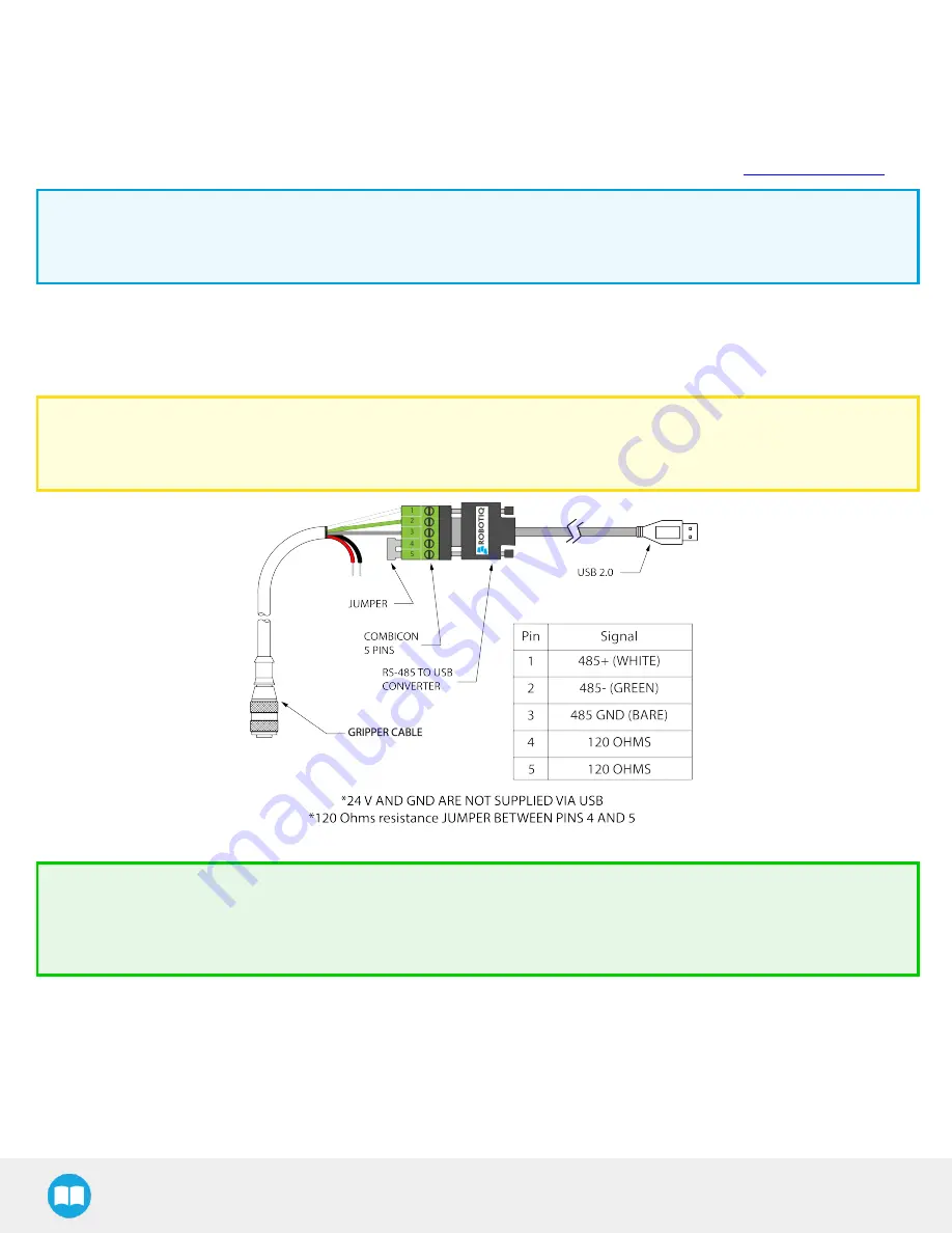
For CB-Series, use the provided RS-485 to USB converter ACC-ADT-USB-RS485 (see RS-485 to USB converter ACC-ADTUSB-

RS485 pinout figure below) to plug into a PC with the Robotiq User Interface installed.

2

Power up your gripper with the previously recommended power supply.

3

Execute the RUI software and select ''auto-connect'' on the connection screen.

4

You are now connected to your gripper, you can click "activate" to begin using the gripper.

Caution

The Activate command will initiate movement of the gripper for auto-calibration procedures. Do not interfere with the

gripper. Be sure you have satisfied robot safety measures.

Fig. 3-18: RS-485 to USB converter ACC-ADT-USB-RS485 pinout.

Tip

With the RUI controlling the gripper, you can go to the view menu to see input and output register values to further your

understanding on how to command the gripper. You can also test grasping objects with various speed and force settings.

See the Control section for details.

36

Summary of Contents for Robotiq 2F-140

Page 1: ...Robotiq 2F 85 2F 140 for Universal Robots Instruction Manual robotiq com leanrobotics org Original Notice 2020 Robotiq Inc...

Page 2: ...5 Electrical Setup 31 3 6 Testing the Gripper with the Robotiq User Interface RUI 36 3 7 Installation for Universal Robots 37 3 8 URCap Package 38 4 Control 47 4 1 Overview 47 4 2 Gripper Register Ma...

Page 3: ...Troubleshooting 141 8 1 Using the LED of the 2F Finger gripper 141 8 2 Using the LED of the USB to RS485 converter 142 8 3 Using the Robotiq User Interface RUI 142 8 4 Troubleshooting Universal Robots...

Page 4: ...ons to standardize with our other manuals Revision 2019 10 10 l Update of the I O Coupling sections l Addition of the Electrostatic Discharge Safety section Revision 2019 07 25 Addition of the I O Cou...

Page 5: ...rd l Gripper Calibration menu and Calibration wizard for object validation Revision 2017 06 06 Added section l 4 8 2 1 Multiple Grippers Revised sections l 3 8 1 Installation procedure for URCaps l 4...

Page 6: ...n for use on Robotiq Universal Controller Minor modifications User Interface section maintenance section Revision 2013 02 06 Section added Couplings ISO models and Baxter robots Minor modifications Re...

Page 7: ...for sale or not without prior written consent from Robotiq Under copyright law copying includes translation into another language or format Information provided by Robotiq in this document is believed...

Page 8: ...esigned for industrial applications Its design makes it a unique robotic end of arm tool to quickly pick place and handle a large range of objects of varying sizes and shapes Info Unless specified inf...

Page 9: ...is configuration allows the fingers to automatically adapt to the shape of the object they grasp which simplifies the control of the gripper Fig 1 1 Robotiq 2 Finger Adaptive Gripper Please refer to t...

Page 10: ...remains the same only the fingers will change Please refer to the Mechanical Installation section for installation instructions Finger kits are available in the Spare Parts Kits and Accessories secti...

Page 11: ...ect to the gripper In other words picking the same object could result in either an encompassing or fingertip grasp based on an object s position and geometry Fig 1 3 2 Finger parallel and encompassin...

Page 12: ...ingers can pick hollow objects from the inside by applying pressure with the outside of the fingers Refer to the figure below for a visual representation and to the Picking Features section for detail...

Page 13: ...e with a parallel motion The figure below shows the encompassing grasp region the equilibrium line and the parallel grasp region on the 2 Finger Adaptive Gripper Info The details of the equilibrium li...

Page 14: ...he Mechanical Installation section for installation of the coupling to the Specifications section for technical drawings and to the Spare Parts Kits and Accessories section for available couplings The...

Page 15: ...ot Gripper l Installation l Control l Maintenance l Inspection l Calibration l Programming l Decommissioning This documentation explains the various components of the 2 Finger and general operations r...

Page 16: ...ground path of the welding power source 2 1 1 Risk assessment and final application The Robotiq 2 Finger Adaptive Gripper is meant to be used on an industrial robot The robot Gripper and any other eq...

Page 17: ...for Universal Robots section l The URCap Package section Warning Before installing l Read and understand the safety instructions related to the 2 Finger Adaptive Gripper l Verify your package accordi...

Page 18: ...ers fingertips and cabling Please refer to the Spare Parts Kits and Accessories section 3 1 1 Robotiq 2F 85 and 2F 140 grippers UR Standard Kit Standard upon delivery for CB Series and e Series l Robo...

Page 19: ...t IO CPL UR CB KIT including l 1 x I O Coupling IO CPL CB l 1 x Screw kit to install on the robot CPL SCREW KIT l 1 x Micro USB to USB cable CBL MICRO USB 6FT l 1 x 16 Go USB Stick ACC USB 16G 3 2 Req...

Page 20: ...rent 1 A Overcurrent Recommended power supply with internal protection otherwise fusing is required 2 A fuse at 25 C 77 F 1 Table 3 1 2 Finger power supply requirements Info 1 Suggested fuse is a Phoe...

Page 21: ...ating conditions of the 2 Finger Adaptive Gripper 3 4 Mechanical Installation 3 4 1 Installing the Gripper on the robot Single Gripper Installation Instructions You must use a coupling to attach the g...

Page 22: ...2F 85 2F 140 Instruction Manual Fig 3 1 Installing the gripper on the robot wrist for CB Series 22...

Page 23: ...2F 85 2F 140 Instruction Manual Fig 3 2 Installing the gripper onto the robot wrist for e Series 23...

Page 24: ...ig 3 3 Robotiq I O Coupling The status LED integrated in the micro USB port presented in the figure above will be l Solid blue red when booting l Solid red when looking for product or waiting for comm...

Page 25: ...g the Gripper onto the I O Coupling 1 Fasten the gripper onto the I O Coupling using the M5 screws and tooth lock washers of the gripper Caution Be careful with the fragile pins while installing the g...

Page 26: ...If the I O coupling got wet make sure the micro USB port is properly dryed before connecting the USB cable 2 Run the Robotiq User Interface RUI to update the firmware You can now use your gripper with...

Page 27: ...rovided M6 X 12 mm screws and tooth lock washers 3 Mount the grippers onto the coupling using the provided M5 X 25 mm screws and tooth lock washers Fig 3 5 Dual 2F Gripper Configuration CB Series and...

Page 28: ...h the corresponding chassis axis 2 Insert the bar axis in the bar hole and through the chassis axis top hole is for parallel locking while bottom hole is for finger install ation 3 Insert the proximal...

Page 29: ...If you need to change the fingertips follow the instructions below 1 Align the fingertip dowel pins with the finger dowel holes 2 Apply low strength threadlocker on the provided screws and secure the...

Page 30: ...Gripper Fingers An optional protector kit AGC PRO KIT V4 AGC PRO KIT 140 can be ordered to cover the fingers of the 2F 85 2F 140 and therefore protect users and assets against pinch points You can ins...

Page 31: ...between the grounds does not exceed 250V Grounding reference is at the user s discretion Fig 3 10 Robotiq 2 Finger electrical isolation grounding 3 5 1 Electrostatic Discharge Safety Robotiq 2F 85 2F...

Page 32: ...ment Make sure to leave enough slack in the cabling to allow movement of the gripper along all axes without pulling out the connectors Always protect the controller side robot side connector of the ca...

Page 33: ...al converter ACC ADT USB RS485 as shown in the figure below Also connect the red 24V and black 0V wires in the controller according to that same figure Fig 3 13 2 Finger Adaptive Gripper wiring to rob...

Page 34: ...g Fig 3 15 Pinout of the I O Coupling 3 5 5 Coupling to wrist for e Series Single Gripper The figure below represents the wiring schematic of the 2 Finger with a coupling connecting directly to the ro...

Page 35: ...or multiple gripper configurations connect the M8 splitter to the robot wrist connector Warning In order to connect two or more grippers at the same time on a robot each gripper must have a coupling f...

Page 36: ...otiq User Interface installed 2 Power up your gripper with the previously recommended power supply 3 Execute the RUI software and select auto connect on the connection screen 4 You are now connected t...

Page 37: ...obotiq Grippers URCap Package 1 3 0 Incompatible Incompatible Incompatible Compatible Incompatible Robotiq Grippers URCap Package 1 3 1 and later versions Incompatible Incompatible Incompatible Compat...

Page 38: ...inger Adaptive Gripper is properly mounted to the robot arm Refer to the Mechanical Installation section for detailed information on the mechanical installation Before installing the URCap package mak...

Page 39: ...ripper Universal Robots Software Gripper Software l Download the UCG X X X and extract its content on the root of a blank USB stick l If an I O Coupling is present install the appropriate URCap by dow...

Page 40: ...s button to add the Wrist Connection s URCaps package Open Robotiq_Wrist_ connectionX X X X urcap from the USB storage device l Restart PolyScope to complete the URCap installation By doing so you acc...

Page 41: ...the USB stick in the UR teach pendant or controller l On the teach pendant tap the triple bar icon in the upper right corner of the screen l Tap Settings l Tap the System button in the navigation pan...

Page 42: ...eck the box Gripper cable is connected to the wrist Fig 3 13 Gripper cable is connected to the wrist Check Box 4 Go to Installation General Tool I O 5 Go to section I O Interface Control and select Ro...

Page 43: ...tructions After a gripper has been identified by PolyScope disconnect it and repeat the installation procedure for each additional gripper l Connect only one gripper at a time using the splitter For C...

Page 44: ...will occur By default Gripper ID is set to 1 in all grippers internal memory When you change gripper ID through PolyScope that change is committed to gripper memory 2 Click on Activate to activate the...

Page 45: ...nger Gripper URCap follow this procedure For CB Series l Go to Setup Robot l Tap URCaps Setup l In the Active URCaps text box tap the Gripper URCap l The Gripper URCap should be highlighted l Tap the...

Page 46: ...icon in the upper right corner of the screen l Tap Settings l Tap the System button in the navigation pane on the left l Select URCaps in the dropdown list l Select the URCap to uninstall l Press the...

Page 47: ...picked once the Go to command has been initiated The feature also works for lost or dropped objects and the user can be alerted if an object is dropped after being detected l In case of emergency auto...

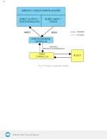
Page 48: ...2F 85 2F 140 Instruction Manual Fig 4 1 2 Finger control logic overview 48...

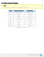
Page 49: ...es and status registers Register Robot Output Functionalities Robot Input Status Byte 0 ACTION REQUEST GRIPPER STATUS Byte 1 RESERVED RESERVED Byte 2 RESERVED FAULT STATUS Byte 3 POSITION REQUEST POS...

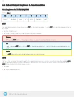
Page 50: ...setting rACT rACT 1 the gripper will begin movement to complete its activation feature Info Power loss will set rACT rACT 1 the rACT bit must then be cleared rACT 0 then set again to allow operation...

Page 51: ...gripper after an emergency stop of the robot The automatic release is not intended to be used under normal operating conditions Automatic release will require the rACT to be cleared rACT 0 then set r...

Page 52: ...m or 140 mm opening respectively l 0xFF Closed l Opening count 0 4 mm for 85 mm stroke and 0 65 mm for 140 mm stroke Info The activation will allow the gripper to adjust to any fingertips No matter wh...

Page 53: ...for the gripper The force will fix the maximum current sent to the motor If the current limit is exceeded the fingers stop and trigger an object detection notification Please refer to the Picking Feat...

Page 54: ...Gripper reset l 0x1 Gripper activation gGTO Action status echo of the rGTO bit go to bit l 0x0 Stopped or performing activation automatic release l 0x1 Go to Position Request gSTA Gripper status retu...

Page 55: ...object detection status being triggered In such applications the Fingers are at requested position status of register gOBJ is sufficient to proceed to the next step of the routine 4 4 2 Register RESE...

Page 56: ...voltage l 0x0B Automatic release in progress l 0x0C Internal fault contact support robotiq com l 0x0D Activation fault verify that no interference or other error occurred l 0x0E Overcurrent triggered...

Page 57: ...gPO gPO Actual position of the gripper obtained via the encoders value between 0x00 and 0xFF l 0x00 Fully opened l 0xFF Fully closed 4 4 6 Register CURRENT Adress Byte 5 Bits 7 6 5 4 3 2 1 0 Symbol gC...

Page 58: ...4 5 1 Force Control The gripping force is controlled via the rFR byte refer to the Robot Output Registers Functionalities section The gripper behavior will change according to the rFR force requested...

Page 59: ...A Durometer 25 220 15 120 Aluminium 60611 95 HV Silicone rubber 40 A Durometer4 25 155 15 100 Aluminium 60611 95 HV Neoprene rubber 10 A Durometer 25 115 15 75 Aluminium 60611 95 HV Polyurethane rubbe...

Page 60: ...2F 85 2F 140 Instruction Manual Fig 4 2 Grip force on hardness 220 HV 4340 annealed carbon steel Fig 4 3 Grip force on hardness 95 HV 6061 T6 aluminium 60...

Page 61: ...2F 85 2F 140 Instruction Manual Fig 4 4 Grip force on hardness 60A silicone Fig 4 5 Grip force on hardness 40 A silicone 61...

Page 62: ...2F 85 2F 140 Instruction Manual Fig 4 6 Grip force on hardness 10 A neoprene Fig 4 7 Grip force on hardness 30 OO polyurethane 62...

Page 63: ...ically set according to the force request rFR Info Feature is off at force request rFR 0 otherwise it is on l Re grasp will keep the position setting l Finger motion will stop when rPR position is rea...

Page 64: ...Fingers have stopped due to a contact while closing before requested position Object detected l 0x03 Fingers are at requested position No object detected or object has been lost dropped Example of co...

Page 65: ...2F 85 2F 140 Instruction Manual 4 6 Control Logic Example Fig 4 8 Example of Gripper control logic with corresponding registers 65...

Page 66: ...http www modbus org docs Modbus_over_serial_line_V1_02 pdf For debugging purposes the reader is also invited to download one of many free Modbus scanners such as the CAS Modbus Scanner from Chipkin A...

Page 67: ...erters are available in the Spare Parts Kits and Accessories section 2 These parameters can be adjusted using the Robotiq User Interface Each register word 16 bits of the Modbus RTU protocol is compos...

Page 68: ...tatus Object Detection Fault Status and Position Request Echo Request is 09 04 07 D0 00 02 70 0E Bits Description 09 SlaveID 04 Function Code 04 Read Input Registers 07D0 Address of the first requeste...

Page 69: ...is 09 10 03 E9 00 02 04 60 E6 3C C8 EC 7C Bits Description 09 SlaveID 10 Function Code 16 Preset Multiple Registers 03E9 Address of the first register 0002 Number of registers written to 04 Number of...

Page 70: ...Object Detection Fault Status and Position Request Echo It also sets the position request speed and force of the gripper by writing to registers 0x03E9 1001 and 0x03EA 1002 Request is 09 17 07 D0 00...

Page 71: ...of data bytes to follow 2 registers x 2 bytes register 4 bytes 1000 Content of register 07D0 09E6 Content of register 07D1 F6C1 Cyclic Redundancy Check CRC Tip Response contents might change dependin...

Page 72: ...00 00 00 00 00 73 30 Bits Description 09 SlaveID 10 Function Code 16 Preset Multiple Registers 03E8 Address of the first register 0003 Number of registers written to 06 Number of data bytes to follow...

Page 73: ...3 registers x 2 bytes register 6 bytes 0100 Value to write to register 0x03E9 ACTION REQUEST 0x01 and GRIPPER OPTIONS 0x00 rACT 1 for Activate Gripper 0000 Value written to register 0x03EA 0000 Value...

Page 74: ...4 Read Input Registers 02 Number of data bytes to follow 1 register x 2 bytes register 2 bytes 1100 Content of register 07D0 GRIPPER STATUS 0x11 RESERVED 0x00 gACT 1 for Gripper Activation gSTA 1 for...

Page 75: ...Value written to register 0x03E8 ACTION REQUEST 0x09 and GRIPPER OPTIONS 0x00 rACT 1 for Activate Gripper rGTO 1 for Go to Requested Position 00FF Value written to register 0x03E9 GRIPPER OPTIONS 2 0...

Page 76: ...04 Read Input Registers 06 Number of data bytes to follow 3 registers x 2 bytes register 6 bytes 3900 Content of register 07D0 GRIPPER STATUS 0x39 RESERVED 0x00 gACT 1 for Gripper Activation gGTO 1 f...

Page 77: ...RESERVED 0x00 gACT 1 for Gripper Activation gGTO 1 for Go to Position Request and gOBJ 2 for Fingers have stopped due to a contact while closing 00FF Content of register 07D1 FAULT STATUS 0x00 POSITI...

Page 78: ...egister 0x03E8 ACTION REQUEST 0x09 and GRIPPER OPTIONS 0x00 rACT 1 for Activate Gripper rGTO 1 for Go to Requested Position 0000 Value written to register 0x03E9 GRIPPER OPTIONS 2 0x00 and POSITION RE...

Page 79: ...e 04 Read Input Registers 06 Number of data bytes to follow 3 registers x 2 bytes register 6 bytes 3900 Content of register 07D0 GRIPPER STATUS 0x39 RESERVED 0x00 gACT 1 for Gripper Activation gGTO 1...

Page 80: ...x00 gACT 1 for Gripper Activation gGTO 1 for Go to Position Request and gOBJ 3 for Fingers are at requested position 0000 Content of register 07D1 FAULT STATUS 0x00 POSITION REQUEST ECHO 0x00 the posi...

Page 81: ...nected to the I O Coupling The I O Coupling detection of the gripper has to be confirmed led blue before doing the sequence otherwise it will not be valid l Doing the sequence once the I O coupling is...

Page 82: ...ation script command rq_activate or rq_activate_and_wait must be preceded by the reset command rq_reset This will force the gripper s activation routine Thus if the gripper was already activated it wi...

Page 83: ...Instruction Manual Fig 4 9 Program Structure Editor Multiple Wrist nodes are available l The Wrist connection Activation node activates the device in the program Fig 4 10 Wrist Connection Activation...

Page 84: ...Tap on the Test button to try each preset Fig 4 11 Wrist Connection Node Interface l The Wrist Grip Check node is pre packaged as an If statement that prompts the user to select between if the object...

Page 85: ...2F 85 2F 140 Instruction Manual l In the Wrist Connection Toolbar you can o Test the 4 presets o See the Object Detection Status o Activate the Gripper Fig 4 13 Wrist Connection Toolbar Interface 85...

Page 86: ...box 6 If no gripper is found tap the Scan button to detect any gripper that might be connected to the robot 7 Tap the Activate Reactivate button 8 In order to display the Gripper Toolbar in the UR men...

Page 87: ...le Gripper for CB Series Open or create a robot program 1 Tap the Installation tab 2 Select Gripper in the left pane 3 Tap the Dashboard button 4 If no gripper is found tap the Scan button to detect a...

Page 88: ...quiring its own scan and activation before going on to the next For each gripper connected follow the required steps in one of the two following sections depending on your robot model the Single Gripp...

Page 89: ...hange ID Tap the arrow next to the text box to expand a list of available gripper IDs Selecting an available number will allocate it to the corresponding gripper E Open Tapping this button sends an em...

Page 90: ...to Installation URCaps Gripper Configuration l For CB Series Go to Installation Gripper Configuration 2 Enter your password Default is rqsafe 3 Tap Unlock 4 To set a maximum opening closing speed for...

Page 91: ...values stand as references only The actual maximum force in newtons can vary depending on the application and needs to be measured by its user by an external measuring system on each gripper for high...

Page 92: ...he Installation tab 2 Select Gripper in the left pane Info A gripper that has not been calibrated will display open and closed values in percentage Fig 4 22 Sequence Toward Calibration Single Gripper...

Page 93: ...2F 85 2F 140 Instruction Manual Fig 4 23 First step of the calibration wizard Fig 4 24 Second step of the calibration wizard 93...

Page 94: ...p this button to access the Gripper Calibration menu Calibrate Recalibrate The Calibrate and Recalibrate buttons launch the Gripper Calibration wizard Default Following a calibration tap this button t...

Page 95: ...pen the Gripper in the Calibration wizard Fully closed Visual aid for entering the fully closed dimension in the Calibration wizard Fully open Visual aid for entering the fully open dimension in the C...

Page 96: ...een to expand the Gripper Toolbar Fig 4 26 UR button to expand the gripper toolbar If the user has omitted to tick the Show Gripper Toolbar box in the Gripper Dashboard tapping the UR button will disp...

Page 97: ...ted at this point the Open and Close values will remain in percentage Please refer to the Gripper Calibration menu and wizard section for instructions Once the gripper is activated the toolbar can be...

Page 98: ...ts settings will be copied over to the others when they are selected In order to modify each gripper s settings individually select a gripper edit it uncheck its box and carry on to the next gripper I...

Page 99: ...ut the functionality is not available e Series UR Menu Gripper Toolbar Tap to toggle between the expanded blue and collapsed black Gripper Toolbar Activate Tap to activate the gripper The gripper will...

Page 100: ...ose Tap to fully close the gripper Requested position Shows the actual position of the gripper according to the system of units defined in PolyScope imperial vs metric If the gripper is not calibrated...

Page 101: ...Functionality Name Description Minus Tap to decrease the corresponding parameter No object detected Icon shown when no object is detected during a grasp Object detected The icon shows a green checkma...

Page 102: ...to the Command tab to edit the Gripper node inserted 6 Tap the Edit action button to edit the node s parameters Info The gripper needs to be activated before it can receive a command To do so use the...

Page 103: ...n the Command window warns that a partial opening closing should not be performed for picking an object l For positioning and partial movement of the gripper moving to a specific position between the...

Page 104: ...ated Edit action Opens the Edit action screen where you can edit the gripper s action parameters Complete motion Selected by default Selected The gripper completes its motion before executing the next...

Page 105: ...t is highly recommended to only use 0 or 100 position when trying to pick an object Node name Node name is automatically set to l Gripper Open when position 0 or fully open value as defined in the Cal...

Page 106: ...y powered connected and activated l When selecting one gripper all buttons are available The action will apply to the selected gripper l When jogging the position the selected gripper will move automa...

Page 107: ...y Requested force Shows the force requested for the selected Gripper node Use the Plus and Minus icons to modify Plus Tap to increase the corresponding parameter Minus Tap to decrease the correspondin...

Page 108: ...display 3 Tap the URCaps menu in the navigation pane on the left 4 Tap the Grip Check button 5 Select the node in the robot program to edit it For CB Series 1 Open a robot program or create one 2 Go...

Page 109: ...nual Fig 4 33 Grip Check node interface with dimension validation Given that the Grip Check node is an If statement tapping the actual node in the Command tab brings up the option to add an Else instr...

Page 110: ...nu If the Gripper firmware version is obsolete a warning message will display and an Upgrade Firmware button will prompt the user to upgrade the firmware to the latest available version Error messages...

Page 111: ...per with I O Coupling UCH 1 0 0 To use the Object Detection feature the Tool Inputs can be used Fig 4 35 Command window Tool Inputs configuration and Object Detect status are Name Description rq_wrist...

Page 112: ...y comparing the finger position when the pick was taught with the similar sized object rq_current_pos_inches Returns the current position of the fingers in inches considering that the PolyScope config...

Page 113: ...il the motion is completed rq_reset Resets the gripper s activation status Use after an autorelease before activating the gripper rq_set_force_norm force Sets the gripper s force defined by the argume...

Page 114: ...2F 85 2F 140 Instruction Manual Multiple Grippers Here is an example of how to use the script commands with more than one gripper Fig 4 36 Example of UR script commands with multiple Grippers 114...

Page 115: ...e data on the various specifications for the Robotiq 2 Finger 85 and 140 Adaptive Grippers l Technical dimensions section l Dimensions of the Gripper l Dimensions of couplings l Dimensions for custom...

Page 116: ...gin referenced for finger motion Fig 5 3 shows the equivalent with 140 mm fingers 2 Finger 140 Info All technical drawings in the present section are shown with NBR overmolded fingertip option AGC TIP...

Page 117: ...2F 85 2F 140 Instruction Manual Fig 5 2 2F 85 dimensions closed Fig 5 3 General dimension of 2F 140 opened...

Page 118: ...ensions closed The height and width of the fingers vary with opening position Fig 5 3 represents the 2F 140 Gripper in the opened position position request 0 while Fig 5 4 represents the 2F 140 Grippe...

Page 119: ...al contacts Info The coupling is common to both the 2F 85 and the 2F 140 Coupling for ISO 9409 1 50 4 M6 Bolt pattern for couplings GRP CPL 062 and GRP ES CPL 062 refer to the Spare Parts Kits and Acc...

Page 120: ...et the following specifications l Fingertip must not exceed 100 mm in height from the fingertip s base l Fingertip must not exceed 100 mm in width from the fingertip s base refer to Y axis from Fig 5...

Page 121: ...represents a flat rubber NBR overmolded fingertip AGC TIP MLD KIT 85 for 2F 85 and AGC TIP MLD KIT 140 for 2F 140 For details see the Spare Parts Kits and Accessories section Fig 5 7 Flat Rubber NBR O...

Page 122: ...ip AGC TIP 205 085 2 Finger 85 and AGC TIP 421 140 2 Finger 140 please refer to the Spare Parts Kits and Accessories section This fingertip inner surface has vertical grooves making ideal for picking...

Page 123: ...e repeatability 10 Position resolution2 0 4 mm 0 016 in 0 6 mm 0 022 in Grasp force resolution Maximum force calculation below refer to the Force Control section Table 5 1 Mechanical specifications of...

Page 124: ...lubricated steel part machine tending with cutting oils the friction coefficient would be 0 3 tested static coefficient of friction The maximum weight with a safety factor of 2 4 using the maximum gr...

Page 125: ...2F 85 2F 140 Instruction Manual Friction grasp and form fit grasp Maximum payload by grasp type Grasp Type 2F 85 2F 140 Friction grasp 5 kg 2 5 kg Form fit grasp 5 kg 2 5 kg...

Page 126: ...in the figure below where l is the opening angle between the gripper proximal bar and center line l D is the distance between the bottom of the fingertips and the equilibrium line as seen on the Z axi...

Page 127: ...40 Instruction Manual 5 2 3 Center of mass tool center point and moment of inertia When grippers are not mounted on the Wrist Camera a coupling is included A dual gripper adapter plate is included whe...

Page 128: ...mounted on a dual gripper assembly is as follows l Rx 0 l Ry Ry 0 7854 l Rz 0 The moment of inertia are calculated for a configuration where the fingers are fully open Here is the approximate moment o...

Page 129: ...on 2 Finger 85 2 Finger 140 Fx Fy Fz 50 N 25 N Mx 5 Nm 5 Nm My 5 Nm 5 Nm Mz 3 Nm 3 Nm Moments in x and y are calculated from the base of the fingertips as shown in Fig 5 15 Fig 5 14 Maximum moment and...

Page 130: ...Instruction Manual 5 3 Electrical specifications SPECIFICATION VALUE Operating supply voltage 24 V DC 10 Absolute maximum supply voltage 28 V DC Quiescent power minimum power consumption 1 W Peak cur...

Page 131: ...y Robotiq Info A cycle is defined as a go to requested position command that results in grip force being applied closing the fingers on themselves or picking an object while opening or closing Operati...

Page 132: ...the maintenance intervals must be adjusted according to environmental conditions such as l Operating temperature l Humidity l Presence of chemicals l Presence of physical parts debris scraps dust gre...

Page 133: ...coupling using the 4 mm hex key to unscrew the four 4 M5 0 8 x 25mm screws Note that each screw uses a tooth lock washer do not lose them 2 Use the flat head precision screwdriver to open or close the...

Page 134: ...ric and fluid i Test the return movement by pushing fingers open the fingers must come back to the initial starting position on its own ii Test the general movement of the fingers by turning the flat...

Page 135: ...ement parts Caution Always turn off the robot and the gripper power supply before performing any maintenance operations 1 Remove and clean the gripper following instructions from the Gripper cleaning...

Page 136: ...s Overhaul is done by Robotiq please contact Robotiq support service Gripper overhaul includes but is not limited to l Worn parts changed l Power transmission gearing mechanism l Plain bearings l Ball...

Page 137: ...unit NBR overmolded fingertips and cable to wrist coupling for Universal Robots AGC ES UR KIT 85 AGC ES UR KIT 140 Controller Optional controller for industrial communications See Robotiq Universal C...

Page 138: ...fingertips l 2 x M5 0 8 x 10 mm SHCS l 4 x dowel pins M2 x 6 mm AGC TIP 205 085 AGC TIP 421 140 Replacement finger l 1 x finger l 4 x screws M3 0 5 X 5 LHCS l 1 x proximal locking shaft l 1 x parallel...

Page 139: ...GRP CPL 064 56 8M4 1D4 coupling Coupling for 56 mm PCD1 with 8 M4 and 1 4mm dowel pin with screws for 2 F Gripper fixation and 1 m pigtail cable AGC CPL 065 002 56 6M4 1D6 coupling Coupling for 56 mm...

Page 140: ...pter plate for use with AGC CPL 064 002 Interface to 80 mm PCD1 with 6 M8 screws and 2 M8 dowel pins AGC APL 153 002 1Pitch Circle Diameter Tip For legacy part replacement visit the documentation arch...

Page 141: ...on LED should turn solid blue when connection is estab lished Blinking blue and red Gripper is in fault 1 Gripper may be in auto release wait for autorelease to be completed then turn off auto release...

Page 142: ...Check the communication parameters from the Robotiq User Interface and see recovery procedure 4 Contact support Quickly blinking red and green 1 Check fault status maximum operating temperature could...

Page 143: ...2 Finger Adaptive Gripper LED is not blue see Table 8 1 Troubleshooting Solutions Depending on Gripper LED Status 2 2 Finger Adaptive GripperLED is blue the latest version of the URCap is installed C...

Page 144: ...140 Instruction Manual 3 Use the 24V slider in the I O tab under the Tool Output section to slide it to 0 and then back to 24V It should enable the com munication with the robot Fig 8 4 Voltage set to...

Page 145: ...ve Robot Gripper as well as verify and adjust the Gripper free of charge if the equipment should need to be repaired or if the original adjustment is erroneous If the equipment is sent back for verifi...

Page 146: ...her items to which the 2 Finger Adaptive Robot Gripper is connected or the operation of any system of which the Gripper may be a part 9 1 I O Coupling Warranty Robotiq warrants the I O Coupling agains...

Page 147: ...external to the Gripper or other factors beyond Robotiq s control Robotiq reserves the right to make changes in the design or construction of any of its products at any time without incurring any obli...

Page 148: ...10 Harmonized Standards Declarations and Certificates 10 1 Translation of original EC declaration of incorporation 2F 85 2F 140 Instruction Manual...

Page 149: ...mance requirements for similar products Caution Conformity of the product is only met if all instructions of this manual are followed Among others installation safety measures and normal usage must be...

Page 150: ...e Licensor s Business 4 End User means a customer authorized pursuant to this Agreement to install or use the Software in order to make a specific product from the Licensor s Products compatible and f...

Page 151: ...are 8 Restricted Use The Software shall be used solely and exclusively by the End User and its employees for the purpose mentioned in Sub section 1 4 hereof Any other use of the Software including res...

Page 152: ...l be governed and construed in accordance with the laws of the province of Quebec and the fed eral laws of Canada applicable therein Any legal action or proceeding between the Licensor and the End Use...

Page 153: ...80 2788 Outside US and Canada Technical support Extension 3 Sales Extension 2 Head office Robotiq 966 chemin Olivier Suite 500 St Nicolas Qu bec G7A 2N1 Canada Where automation Pros come to share thei...

Reviews: