background image

L4

Aluminium

The hole Φ5mm

WPC

Aluminium

WPC

12

STEP:2

STEP:3

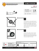
Pre-drill the cross beams (C). ATTENTION: Do not pre-drill the inner aluminum.

Measure the distance of the cross beams (C) as the diagram shown which is 222mm/8.74” and mark the points.

222mm/8.74”

222mm/8.74”

Fix the screws (L4) on the cross beams (C).

Summary of Contents for WPC PERGOLA

Page 1: ...Option A Option B INSTALLATION INSTRUCTIONS WPC PERGOLA 10 x10 ...

Page 2: ...269mm 10 59 269mm 10 59 Base plate cover 3048mm 120 3048mm 120 3048mm 120 2052mm 80 76 2454mm 96 6 2454mm 96 6 2835mm 111 6 ...

Page 3: ...L1 U clip X16 L2 M8 60mm screw bolt X16 L3 L angle clip X105 L4 4 2X25mm screw X270 L5 Expansion screw X16 L6 M10 treaded rod X12 L7 3 8X25mm screw X40 Base plate cover X4 Drill ...

Page 4: ... to the measurement please put the steel inner post A on the ground ATTENTION The ground should be flat STEP 1 STEP 2 Z Z 198mm7 8 198mm7 8 Between80 90mm 3 15 3 55 2501mm 98 4 2501mm 98 4 2105mm 82 8 2105mm 82 8 attention Note Please drill the holes as the diagram shown Drill the points Straight line Straight line ...

Page 5: ...the B over the A When touching th WPC part please wear gloves in case there is oil on the WPC posts Before fixing the posts to the ground refer to the front page of the guide option A or option B using the pre drilled holes on the end of the posts choose the orientation of the desired roof structure same STEP 3 STEP 4 STEP 5 2 4 Straight line Straight line same ...

Page 6: ...2 1 Use the Level to ensure the a side and b side of the posts must be vertical to the ground Please adjust if necessary Use the wrench to fix the expansion screws L5 2 The ground should be flat Straight line Straight line 2454mm 102 2454mm 102 5 STEP 6 STEP 7 STEP 8 3 Straight line Straight line Post Installation A B ...

Page 7: ...Put the base plate covers H on the WPC posts 6 2454mm 102 2 4 5 4 m m 1 0 2 2454mm 102 2454mm 102 Measure again B STEP 9 ...

Page 8: ...he U Clips L1 as the diagram shown STEP 2 Install the cross beams C with the treaded rod L6 and the U clips L1 8 pieces 4 pieces L6 L1 middle top bottom Note Please adjust the distance between the posts according to the holes position on the C ...

Page 9: ...e Keep the screws L7 parallel to the cross beam C Keep Parallel Keep Parallel L7 L7 Please pre drill the holes for the screws L7 with Φ4mm Φ0 2 and fix the screws L7 Please do not pre drill the inner aluminum STEP 3 ...

Page 10: ...rain holes must be downwards Install the beams 2 F to the cross beams C with the U Clips L1 and the screws bolt L2 Note Please use the wrench to fix the L2 go through the holes of the F tightly Beam F installation ...

Page 11: ...rill the inner aluminum Fixing the U Clips L1 and screws L7 with the holes we pre drill as the diagram shown Use the wrench to install the beam 3 G with the screws bolt L2 tightly Fix the beam 3 G according to the 6 cuts of the beam 1 2 E L7 L7 L7 L7 Keep Parallel Keep Parallel Beam G installation ...

Page 12: ...L4 L3 Fix the L angle clips L3 and the screws L4 to the beams D STEP 1 Fix the L angle clips L3 and the screws L4 to the beams D Put the beams D on the cross beams C one piece on each side Beam D installation ...

Page 13: ...TEP 2 STEP 3 Pre drill the cross beams C ATTENTION Do not pre drill the inner aluminum Measure the distance of the cross beams C as the diagram shown which is 222mm 8 74 and mark the points 222mm 8 74 222mm 8 74 Fix the screws L4 on the cross beams C ...

Page 14: ...E the distance P is 269mm 10 59 and mark the points E 7 E P P P P P P P P 8 STEP 1 There are 6 cuts on each pieces Please adjust the cuts to fit onto the cross beams C 13 Beam E L4 L3 Fix the L angle clips L3 and the screws L4 to the beams E Beam E installation ...

Page 15: ...s on the WPC beam and do not pre drill the inner aluminum Fix the screws L4 and measure again the distance as the Page 1 show STEP 2 STEP 3 Aluminium The hole Φ5mm WPC Aluminium WPC L4 Fix the screws L4 on the cross beams C 14 ...

Reviews: