background image

Freezing Channels

Camera 1

Camera 2

Camera 3

Camera 4

1234

1234 09/07/2001 14:30:00

{

{

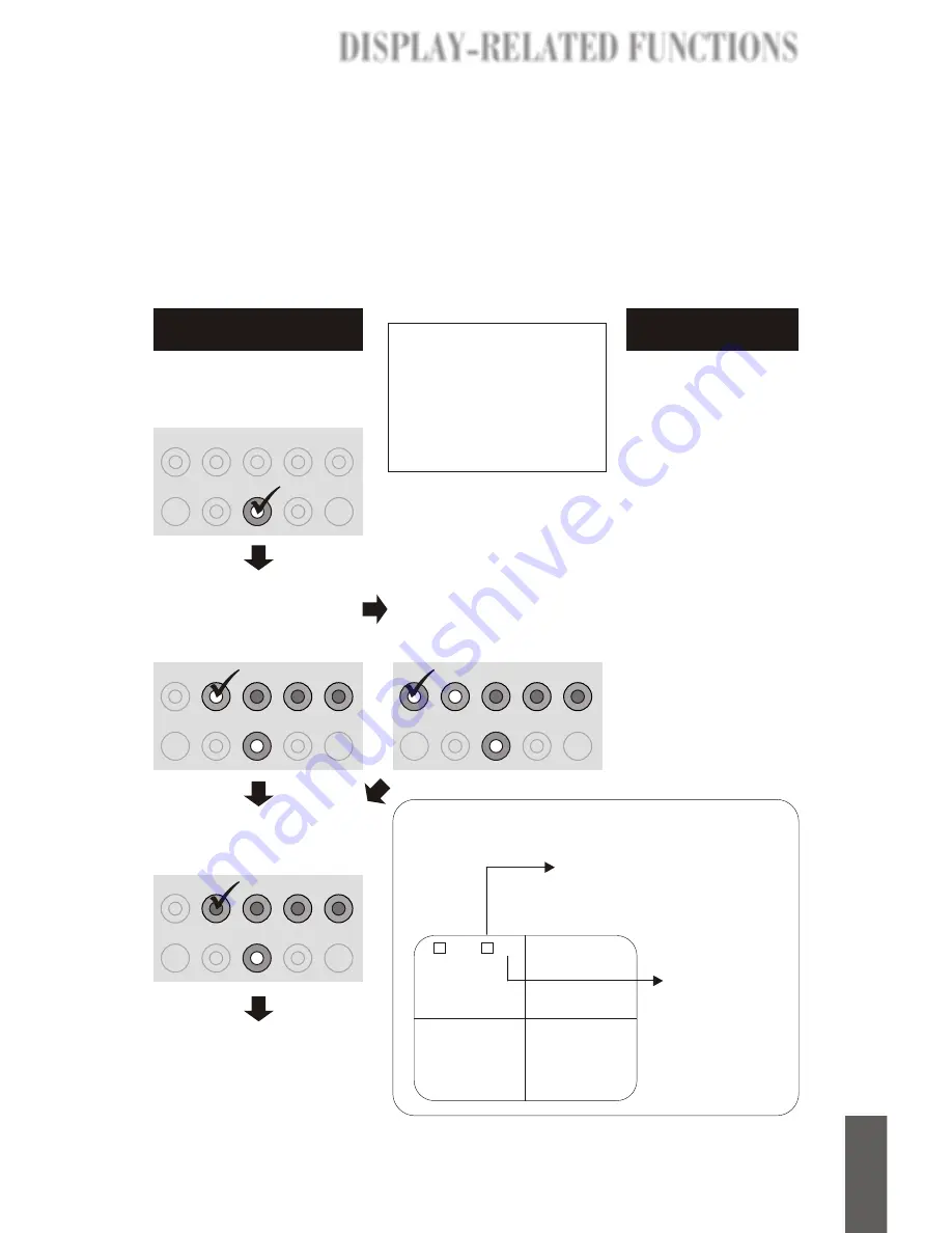
The square icon with a capital
'F' in it indicates the Freeze 
function is being used.

The four digits 
are channel 
numbers. The 
numbers of 
frozen channels 
blink.

The Freeze function is available for fixed input channels, all four channels in 
the QUAD mode, both channels in the PIP mode, all three channels in the 
2PIP mode, the channel displayed in the main frame under the Sequence PIP 
mode, and the channel displayed in the single mode. 

How to freeze a channel

Press the 

FREEZE

 button. 

The LED in the center of the 
button lighted.

CH 1

CH 2

CH 3

CH 4

ZOOM

SETUP

ENTER

FREEZE

PICTURE

MODE

Press one of the four 
channelbuttons. The LED 
lighted and the selected 
channel is frozen.

Under QUAD, PIP, 

& 2PIP modes

Under QUAD, PIP, 

& 2PIP modes

To use freeze function
in these two modes, 
simply press the 

FREEZE

 button, then 

the channel displayed 
in the main frame under 
Sequence PIP mode 
and the video under 
Single mode will freeze. 

See the instructions 
given in the columns to 
the left for how to view 
snapshots, release a 
frozen channel and 
terminate the freeze 
function.

Under Sequence PIP

& Single mode

Under Sequence PIP

& Single mode

Press the frozen channel
button again to release it. 
The LED is put out.

CH 1

CH 2

CH 3

CH 4

ZOOM

SETUP

ENTER

FREEZE

PICTURE

MODE

CH 1

CH 2

CH 3

CH 4

ZOOM

SETUP

ENTER

FREEZE

PICTURE

MODE

CH 1

CH 2

CH 3

CH 4

ZOOM

SETUP

ENTER

FREEZE

PICTURE

MODE

You can now freeze another
channel or pressing the 

FREEZE

 button to terminate 

the Freeze function.

NOTE:

Pressing the 

FREEZE 

button at any time when the 
Freeze function is enabled 
will terminate the Freeze 
function, and the frozen 
channels will be released.

Reading the screen

Press the SETUP button to
view the 4 snapshots of the 
frozen channel.

*

Note

:  

Upon freezing a 

channel, 4 snapshots are 
captured and saved, each at 
a different time at regular 
intervals. 

DISPLAY-RELATED FUNCTIONS

DISPLAY-RELATED FUNCTIONS

DISPLAY-RELATED FUNCTIONS

DISPLAY-RELATED FUNCTIONS

8

E-

E

n

g

lu

s

h

Summary of Contents for SecurityDVR LTR-3100

Page 1: ...USER S MANUAL ...

Page 2: ...SecurityDVR LTR 3100 User s Manual Version A February 2002 SecurityDVR LTR 3100 A 2002 2 CODE LR3100 P N W0500520 ...

Page 3: ...play Related Functions E 5 Quad Processor E 5 Display styles E 5 Setting the Display Styles E 6 Assigning Displayed Channels E 7 Freezing Channels E 8 Using Zoom Function E 9 Arbitrary Zooming E 9 Predifined Zooming E 10 Managing Display Environment E 11 Software Setup E 11 Video Recording Playback E 12 Recording Playback Control Buttons E 12 Recording E 12 To start the recording E 12 To stop the ...

Page 4: ... Setup OSD E 17 How to open the OSD Menu E 17 Operating the OSD E 17 File Management E 18 To partition Hard Disk in mobile rack E 18 To erase data from mobile rack E 19 To erase data from system Hard Disk E 19 Backing up Data E 19 System Timer Setting E 20 Video Recording E 21 Setting time lapse for recording E 21 When Hard Disk if full E 22 Network E 23 Language E 23 Remote Surveillance E 24 Inte...

Page 5: ...Setting Connection Speed E 24 Set LTR 3100 s IP E 25 Changing user Name and Password E 26 FCC Statements 27 TABLE OF C TABLE OF C TABLE OF CONTENTS TABLE OF CONTENTS ...

Page 6: ... Processor that provides a variety of how video from each channel is displayed You can also check on the monitored area from any corner of the world with Internet access at any time LTR 3100 is immediately ready for various types of network such as Ethernet xDSL or cable modem routers for your specified surveillance application This ingeniously integrated product is a perfect replacement for a cos...

Page 7: ...nus Control Quad Processor and display related functions the smaller inner circles at the centers of some buttons are LEDs which will be lighted when some functions are being used Front view of the unit Front Panel Back Panel Camera input connectors TV output connector Ethernet Connector Power Connector For external control Power voltage selection switch 115V 230V It is crucial to switch the power...

Page 8: ...u operate or store SmartTV USB Please follow the instructions given here for the protection of the unit Installation Adjustments Operation Environment 115 PAL NTSC Camera input connectors Each channel connects a camera installed at a monitored site See 1 below See A 2 below 1 Adjust the power voltage switch 115V 230V It is crucial to switch then power voltage to suit that of your power outlet Fail...

Page 9: ...al of your hard drive 4 Step 3 Unlock the mobile rack with the key Step 4 Pull the mobile rack out as shown in the figure below Step 5 Slide open the cover of the mobile rack as shown in the figure below Step 6 Connect the cables referring to the instruction manual of your hard drive Step 7 Place the hard drive in the mobile rack as shown in the figure below Step 8 Put the cover back on the mobile...

Page 10: ...another in the sub frame See the next page for how to select the channels to be viewed under this mode Under 2 PIP 2 Pictures in Picture mode the screen displays one channel in the main frame and two other channels in the sub frames See the next page for how to select channels to be viewed under this mode Displays one channel in the main frame and the other three channels in the sub frame in turn ...

Page 11: ...source will be from channel 2 Note Each time you power on or reset the LTR 3100 it goes under the QUAD mode automatically Camera 1 Camera 2 Camera 3 Camera 4 L 1234 09 07 2001 14 30 00 Camera 1 L 1234 09 07 2001 14 30 00 Camera 1 Camera 2 L 1234 09 07 2001 14 30 00 L 1234 09 07 2001 14 30 00 Camera 1 Camera 2 Camera 3 Camera 1 Camera 2 L 1234 09 07 2001 14 30 00 L 1234 09 07 2001 14 30 00 Camera 1...

Page 12: ...NTER FREEZE PICTURE MODE Step 3 Press another two channel buttons The channels selected will display in the sub frames channel 3 4 in this example L 1234 09 07 2001 14 30 00 Camera 3 Camera 2 Camera 4 CH2 CH3 CH4 CH 1 CH 2 CH 3 CH 4 ZOOM SETUP ENTER FREEZE PICTURE MODE Result CH 1 CH 2 CH 3 CH 4 ZOOM SETUP ENTER FREEZE PICTURE MODE Selecting the Channel to be viewed in the main frame under Sequenc...

Page 13: ...he channel displayed in the main frame under Sequence PIP mode and the video under Single mode will freeze See the instructions given in the columns to the left for how to view snapshots release a frozen channel and terminate the freeze function Under Sequence PIP Single mode Under Sequence PIP Single mode Press the frozen channel button again to release it The LED is put out CH 1 CH 2 CH 3 CH 4 Z...

Page 14: ...is lighted A hollow frame appears in the center of the screen as shown in the screen below Camera 1 Camera 2 Camera 3 Camera 4 L 1234 09 07 2001 14 30 00 Step2 Specify an area Move the hollow frame and locate your desired area using the four channel buttons They are defined as below CH 1 CH 2 CH 3 CH 4 down up left right Step3 Zoom in on specified area Press the ENTER button to execute the zooming...

Page 15: ...ETUP button The LED is lighted The Predefined Zooming is initiated by zooming in on the top left predefined area Step 3 Zoom in on a predefined area View the predefined zoomed areas by pressing one of the channel buttons CH1 CH2 CH3 CH4 SETUP ZOOM ENTER FREEZE PIC TURE MODE CH1 CH2 CH3 CH4 SETUP CH1 Top left Button CH 2 Top right CH 3 Bottom left CH 4 Bottom right Predefined Area Screen Icon L 123...

Page 16: ...next character sequentially Go to the submenu of the selected option in the main menu And save the setting CHANNEL NAME CH1 CAMERA 1 CAMERA 1 CH2 CAMERA 2 CAMERA 2 CH3 CAMERA 3 CAMERA 3 CH4 CAMERA 4 CAMERA 4 You can change the channel names as desired The channel names are displayed on the bottom of the screen or below the sub screens DATE TIME 09 06 2001 09 06 2001 18 22 5 4 18 22 5 4 The time an...

Page 17: ...f the unit To start the recording To stop the recording Recording Playback Control Buttons REC STOP Press to stop recording Press to start recording while the system is inactive The circle in the center of the button is a LED It is lighted when the system is recording video and blinks when the system is playing back video When there is recording in progress pressing the STOP button will stop the r...

Page 18: ...st playback In reverse motion When the system is inactive neither recording nor running the OSD pressing the REV button will start the reverse playback at the normal speed from the end of the last recording To stop the playback PLAY STILL Press to play back the recorded video FWD Press to play back the video in fast forward motion REV Press to play back the video in reverse motion STOP Press to st...

Page 19: ...ime you press the REV button again Press the FWD button to slow down the rewinding Each time you press the FWD button again the rewinding goes slower and eventually turns into fast forward motion Keep pressing the FWD button will speed up the fast forward Press the SLOW button to playback the video in slow reverse motion Press it again to return to the normal rewinding speed When the rewinding is ...

Page 20: ...hed time The Start and End time display on the screen remind you of the starting and ending time of the entire length of video If no video was recorded at the starting time set for Time Searching the system will find what s closest to the setting time and display it The system s failing to find the accurate starting time may be caused by the difference between Quad Processor timer and system timer...

Page 21: ...oom in on the upper right corner of the screen press the button again the lower left corner and again the lower right corner See the figure below Paused SLOW Zoom 1 Zoom 2 SLOW Press Press Zoom 3 Zoom 4 L 1234 09 07 2001 14 30 00 SLOW Press SLOW Press L 1234 09 07 2001 14 30 00 Paused SLOW Press L 1234 09 07 2001 14 30 00 L 1234 09 07 2001 14 30 00 L 1234 09 07 2001 14 30 00 L 1234 09 07 2001 14 3...

Page 22: ... System HD Back up System HD System Timer Setting System Timer Setting page Video Recording Time Lapse Disk Full Time Lapse setup page Overwrite Automatically Clear Data Manually Language English Chinese Network Network setup page Operating the OSD The six buttons on the bottom of the OSD screen are an analogue of the six playback recording buttons on the front panel of the unit giving instruction...

Page 23: ...nd make new partitions File Management Submenu New hard disk alert When you use the system with a Hard Disk in the mobile rack for the first time the system will show the New Hard Disk Found alert message on the screen as the screen shot to the right You need to partition the Hard Disk as instructed above The File Management submenu allows you to manage the recorded data on your hard disk The sett...

Page 24: ...sk Select Clear Data under System HD and press the REC button A warning message will then appear This will erase all data Holding the REC button down to perform the command See the figure below To erase data from mobile rack Select Clear Data under HD in Mobile Rack and press the REC button A warning message will then appear This will erase all data Holding down the button to perform the command S...

Page 25: ...r and highlight the year setting of the timer see the figure below You can now start changing the timer setup Apart from the system timer the Quad Processor also has a timer We suggest that you synchronize these two timers before you start using the playback recording related functions Refer to page E 11 for how to set the timer for Quad Processor The synchronization of the two timers is crucial f...

Page 26: ...eo Recording menu and press the REC button OK The Time Lapse setup OSD will then appear on the screen see the figure below Highlight a setting as desired and then press the REC button OK to save the new setting The default setting for Time Lapse is 15 fps for NTSC and 13 fps for PAL Main Menu Video Recording submenu Setting time lapse for recording Video Recording submenu Under NTSC system Under P...

Page 27: ...enu Select Clean data manually and press the REC button OK By doing this setting the system will display an alert message The Hard Disk is full and unable to record any more data on the screen when the hard disk is full and the system is unable to continue the recording see the bottom figure to the right You need to go to the File Management OSD submenu and run the Clear Data command to clear the ...

Page 28: ... left arrow or SLOW right arrow button will bring out the highlight see the figure below that allows you to change the Network setup Language The Language setup OSD allows you to choose your system language either as English or Chinese Select Language on the main menu and press the REC button OK The Language OSD will then appear on the screen as shown in the figure below Main Menu Language Setup O...

Page 29: ...rd as shown in the screen shot below Defaults User Name root Password root After entering the user name and password the browser will open the surveillance home page as shown in the screen shot to the left Home Page Setting connection speed On the surveillance home page there are 5 speed buttons on the left hand side of the screen Please see the table to choose a speed that suits your type of conn...

Page 30: ...etwork Then the IP setup page will appear as in the second figure to the right 3 Enter the data provided by your Internet service provider ISP ThenClick on Set up Network Then Click OK You need to set LTR 3100 s IP as assigned by your Internet service provider ISP to locate the surveillance website on the internet REMOTE SURVEILLANCE REMOTE SURVEILLANCE VEILLANCE VEILLANCE 25 E ...

Page 31: ...assword on the menu page The browser will go to the page for setting such settings After entering your new username and password click OK Now You can view the surveillanced video as displayed on the TV monitor by log on the Security DVR web page at the IP you just set REMOTE SU REMOTE SU REMOTE SURVEILLANCE REMOTE SURVEILLANCE 26 E Englush ...

Page 32: ...munications However there is no guarantee that interference will not occur in a particular installation If this equipment does cause harmful interference to radio or television reception which can be determined by turning the equipment off and on the user is encouraged to try to correct the interference by one or more of the following measures Reorient or relocate the receiving antenna Increase th...

Reviews: