


EM882S Digital Stepper Drive User Manual
Motion Control Products Ltd. Tel.: (+44) 01202 599922
flowing through motor coils (even when motor is at standstill). Pulling or plugging connector P4 with power on
will cause extremely high back-EMF voltage surge, which may damage the drive.
9.
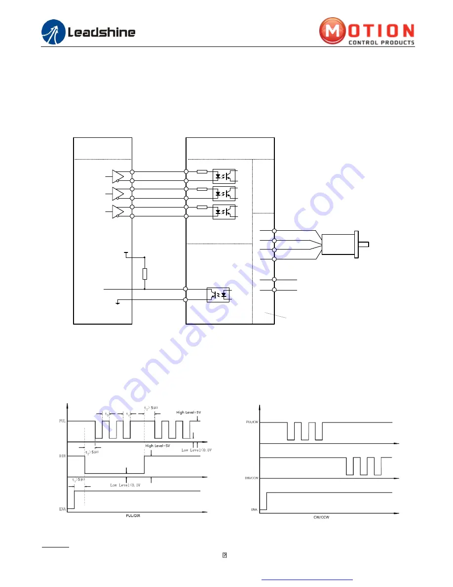
Typical Connection
A complete stepping system should include stepping motor, stepping drive, power supply and controller (pulse
generator). A typical connection is shown as figure 12.
GND
A+
A-
+Vdc
1
5
6
Power &
Motor Connector
Controller
Control Signal
Connector
4
PUL+
1
DIR+
3
PUL-
DIR-
2
4
ENA+
5
ENA-
6
Step
Direction
Enable
Fault
5-24VDC
ALM+
1
2
ALM-
Status Signal
Connector
18-36VDC recommended,
leaving rooms for voltage fluctuation
and back EMF of the motor
2
3
B+
B-
Drive
Figure 12
Typical connection
10.
Sequence Chart of Control Signals
In order to avoid some fault operations and deviations, PUL, DIR and ENA should abide by some rules, shown as
following diagram:
Figure 13
Sequence chart of control signals
Remark:
a)
t
1
: ENA must be ahead of DIR by at least 5 s. Usually, ENA+ and ENA- are NC (not connected). See


