User Manual Of EL7-EC** AC Servo
126
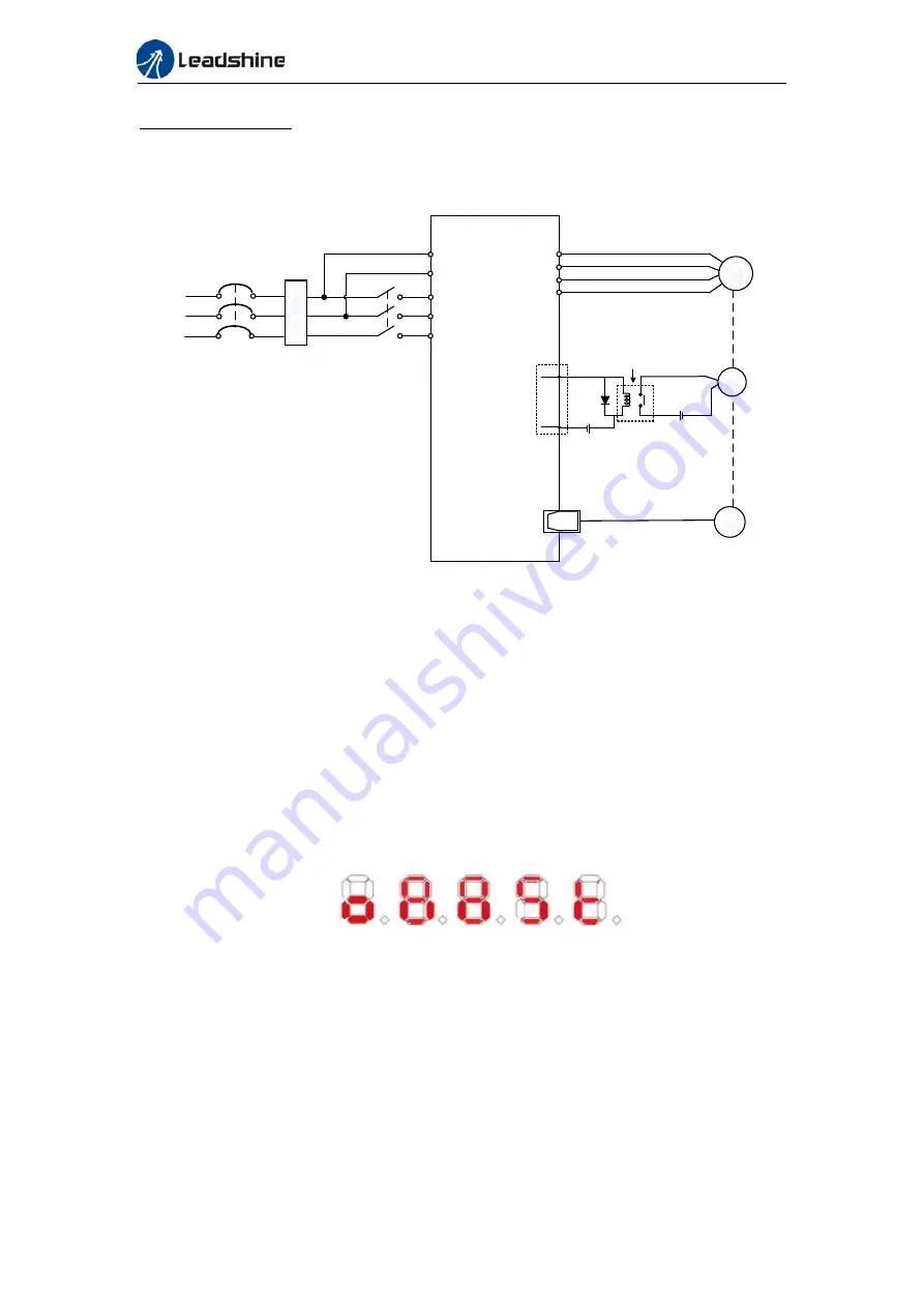
Holding brake wiring
Holding brake input signal is without polarity. An isolated 24V switching power supply is
recommended to prevent abnormal holding brake behavior in case of sudden drop in
working current or voltage.
Li
ne f
ilt
er
Servo Driver
L1C
L2C
M
SG
BK
Brake Relay
BK-RY
DC 24V
Holding
brake
Encoder
Motor
U
W
V
3P
380VAC
CK2
CK1
DO2+(BRK+)
DOCOM-(BRK-)
DC24V
Brake power supply
PE
R
T
S
Wiring diagram of motor holding brake
4.1.6 Servo Running
1. Enable servo driver
Check if CN3/CN4 is connected properly. Servo driver is in ready mode. Motor is stopped
and holding brake is activated. Front panel display shows 402 state machine =
Operational, EtherCAT communication status = operational, Running mode = 8, servo is in
stop mode.
2. Motor starts to move after command input
i.
On first time operation, please use suitable command at low velocity. Confirm if
motor is working normally.
ii.
Check if motor rotational direction is correct. If not, please check input command or
parameter settings. (Pr0.06).
iii.
If motor is working normally, motion data such as motor rotational velocity “d01SP”
and actual torque feedback “d04tr” can be monitored on the front panel or through
Motion Studio.


