CS2RS Series Modbus RS485 Closed Loop Stepper Drive User Manual
- 36 -
RS485 communication trigger JOG:
Write value 0x4001 to 0x1801, JOG+.
Write value 0x4002 to 0x1801, JOG-.
JOG velocity: Pr6.00 (0x01E1).
JOG acceleration and deceleration time: Pr6.03 (0x01E7).
JOG quick stop: write value 0x40 to 0x6002.
Note: JOG triggered by RS485 communication will run continuously only if the trigger interval is less than 50ms, otherwise it
can only point operation.
IO trigger JOG:
Assign JOG+ and JOG- to IO port
.
Then through input level to trigger JOG function.
JOG velocity: Pr8.39 (0x6027).
JOG acceleration time: Pr8.40 (0x6028).
JOG deceleration time: Pr8.41(0x6029)
JOG quick stop: write value 0x40 to 0x6002; or trigger forced quick stop input to IO port; or stop giving IO port level if
using level trigger method.
Example for JOG+ /- and IO Trigger
CS2RS uses JOG+/JOG- to achieve forward and reverse rotation operation; the running velocity can be set in JOG velocity and
JOG velocity 2, then through the external IO signal to realize the two velocity switching. During the is running, the value of
velocity can be modified and effect in real time. The path motion can also be triggered by external IO.
SI1 is set to enable input by default, normally closed.
SI2 is set to JOG+, used for positive directional velocity operation.
SI3 is set to JOG-, used for negative directional velocity operation.
SI6 is set to JOG velocity 2, used for JOG high and low velocity switching.
SI4 is set to trigger signal CTRG, which is used to trigger path motion.
SI5 is set to ADD0, used to select path number.
Note: the value of Pr8.38 is as JOG velocity 2, the value of Pr8.39 is as JOG velocity.
When SI2 is switched on, the motor runs in the positive direction of JOG velocity.
When SI3 is switched on, the motor runs in negative JOG velocity.
When SI6 is switched on, the motor switches to JOG velocity 2 operation.
If SI2and SI3are not switched on, the motor stops.
When SI4 is switched on, start running on Path 0,
refer to Section 5.4.2
When SI5 is switched on, then SI4 on, and start running on Path 1,
refer to Section 5.4.2
5.3.3 Quick Stop
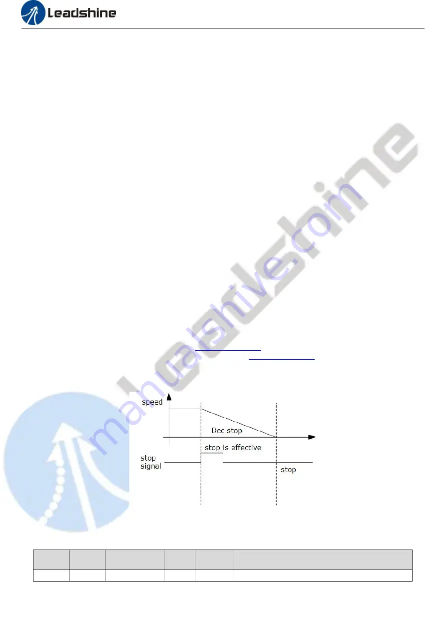
The CS2RS series drives have two types of quick stop: digital input quick stop signal and register quick stop.
Quick stop time sequence
Relevant objects:
Register
address
Par. # in
software
Definition
Range
Default
Value
Description
0x6017
Pr8.23
Quick stop time
Deceleration time after quick stop, unit: ms


