D
D
C
C
S
S
8
8
1
1
0
0
S
S
D
D
i
i
g
g
i
i
t
t
a
a
l
l
D
D
C
C
S
S
e
e
r
r
v
v
o
o
D
D
r
r
i
i
v
v
e
e
r
r
M
M
a
a
n
n
u
u
a
a
l
l
R
R
e
e
v
v
1
1
.
.
0
0
Tel: (86)755-26434369
5
Website: www.leadshine.com
More about +5V, PUL, DIR, ERR/RES Signals
Pin Function
Details
+5V
+5V Opto-coupler power supply.
PUL
Pulse signal: In single pulse (pulse/direction) mode, this input represents
pulse signal, each rising or falling edge active (software configurable); 4-5V
when PUL-HIGH, 0-0.5V when PUL-LOW. In double pulse mode
(pulse/pulse) , this input represents clockwise (CW) pulse
,
active both at high
level and low level (fixed level software configurable). For reliable response,
pulse width should be longer than 2.5
μ
s. Series connect resistors for
current-limiting when +12V or +24V used. The same as DIR and ENA
signals.
DIR
DIR signal: In single-pulse mode, this signal has low/high voltage levels,
representing two directions of motor rotation; in double-pulse mode
(software configurable), this signal is counter-clock (CCW) pulse
,
active
both at high level and low level (fixed level software configurable). For
reliable motion response, DIR signal should be ahead of PUL signal by 5
μ
s
at least. 4-5V when DIR-HIGH, 0-0.5V when DIR-LOW. Please note that
rotation direction is also related to motor-driver wiring match. Exchanging
the connections of two wires of the motor to the driver and A/B phase signals
of encoder will reverse motion direction.
ERR/RES
ERR/RES Pin: Used to output error and reset the DCS810S to clear errors.
+5 VDC when driver is normal. If protection functions such as over-voltage,
over-current, phase error, encoder error, position following error are
activated, ERR/RES pin will be pulled to LOW level (EGND).
Only
Position
Following Error can be cleared by connecting the E+5V to ERR/RES, and
the users should repower the driver to clear other errors after removing other
related problem(s).
DIP Switch SW1, SW2
There are two DIP switches (SW1 and SW2) can be used to select 4 group servo
parameters stored in EEPROM of the driver. The user can select one group of these
servo parameters to optimize the performance for different applications, in which
using different motors or having different load. For most applications, these two DIP
switches should be both on OFF position (Factory Default Status), saving/selecting
D
D
C
C
S
S
8
8
1
1
0
0
S
S
D
D
i
i
g
g
i
i
t
t
a
a
l
l
D
D
C
C
S
S
e
e
r
r
v
v
o
o
D
D
r
r
i
i
v
v
e
e
r
r
M
M
a
a
n
n
u
u
a
a
l
l
R
R
e
e
v
v
1
1
.
.
0
0
Tel: (86)755-26434369
6
Website: www.leadshine.com
the user
’
s own servo parameters, NOT other 3 group for dedicated applications.
Control Signal Connections
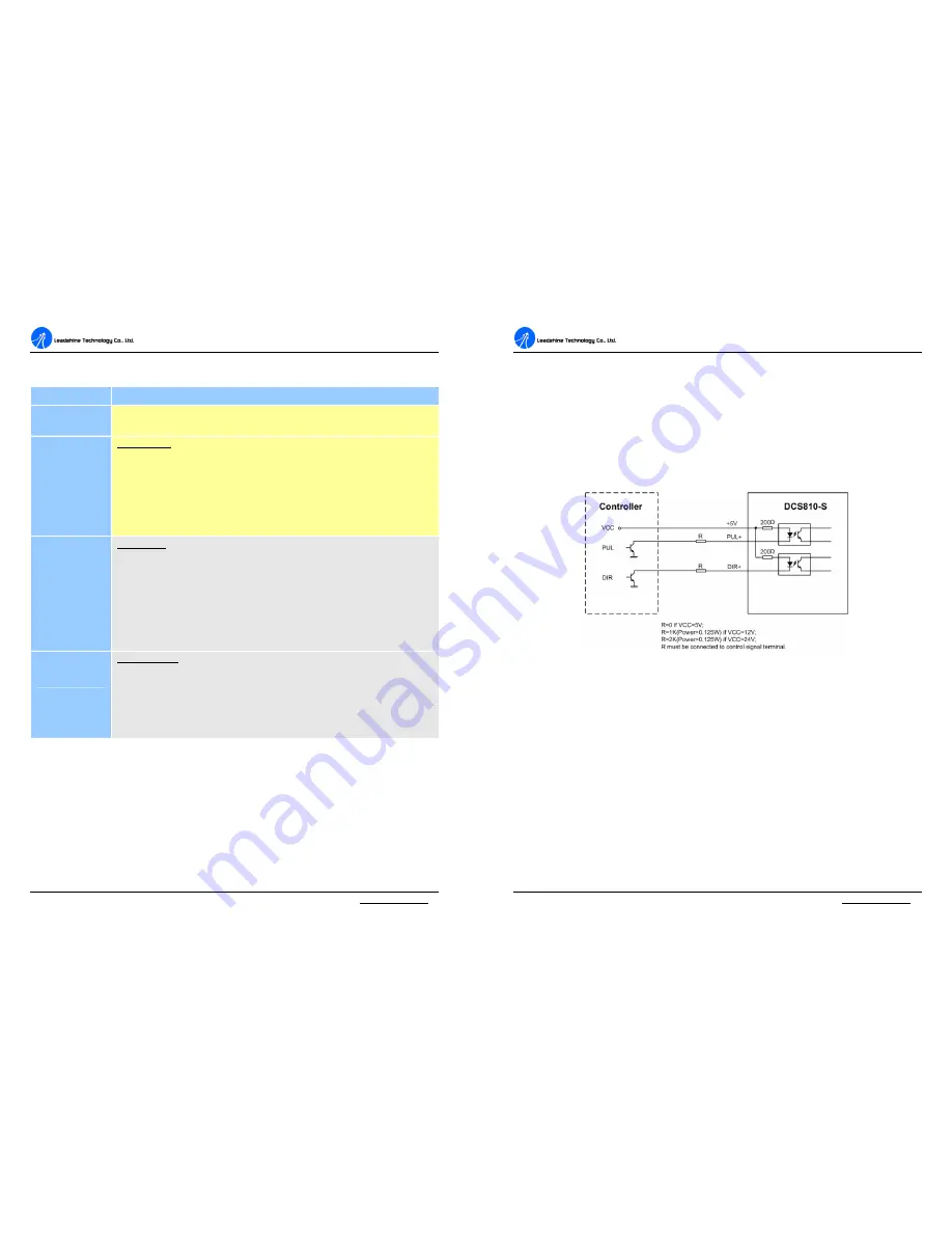
The DCS810S has 2 optically isolated logic inputs to accept PUL/DIR control
signals. These inputs are isolated to minimize or eliminate electrical noises coupled
onto the control signals. In the following figure, connections to open-collector
control signals are illustrated.
Figure 2: Connections to open-collector control signal (common-anode)
Encoder Connections
The DCS810S can accept encoder input from single-ended incremental encoders.
Note that twisted-pair shielded cabling provides the best immunity in electrically
noisy environments.
If the encoder drains less than 50mA, the DCS810S can supply the encoder directly,
and connect it as Figure 3. If the encoder drains more than 50mA, use an external
DC supply and connect it as Figure 4.


