


Tel: +44 (0)845 652 0396
Skyrrid Farm, Pontrilas, Hereford. HR2 0BW. UK
www.leturbines.com
Page 12 of 47
9)
Install the Transmission Cables - When your tower or mount bracket is ready to receive its
turbine, the next stage is to run the cables from the top of the tower to where the
electrical controller and batteries / grid-tie inverter will be located. Follow the table below
to select the correct wire size (cross-sectional area). This will vary depending on your
nominal battery voltage and the distance that the cables will be run. Careful selection of
the cable size is required. It will not only affect the safety of the system, but also the
overall efficiency. A cable of insufficient cable size will cause a voltage drop, wasting the
power that has been generated. The cable sizes listed below have been selected with
efficiency and cost in mind, as it is unlikely that your turbine will be running at full capacity
100% of the time. If in doubt, consult your local electrical supplier. The cable should be
installed in accordance with local electrical regulations and guidelines. If in doubt, use a
local electrical contractor to complete the cable installation.
Warning: If a cable of insufficient cross-sectional area is used, heat will build up in the cables
causing a potential fire hazard. Cable capacities quoted below are based upon ‘Tri-Rated’ cables
(BS6231).
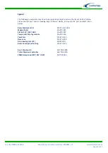
Transmission Distance
LE-450 Nominal Output
Voltage
10 Metres
(30 Feet)
30 Metres
(90 Feet)
100 Metres
(300 Feet)
12 Volts
6 mm²
10 mm²
Not Recommended
24 Volts
1.5 mm²
6 mm²
16 mm²
48 Volts
1.5 mm²
2.5 mm²
4 mm²
10)
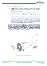
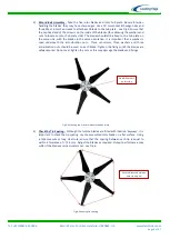
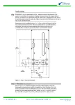
Mount the LE-450 Turbine onto the Support Structure - Ensure that the previously
installed power transmission cables are not yet connected to any batteries and are
‘shorted’ together. This will prevent the turbine from operating during the installation
process. Once this has been done, connect the turbine output cables to the transmission
cables using a suitable terminal block with a minimum rating of 40 Amps. Offer the turbine
up to the support structure and push the turbine body onto the tower. Ensure that no
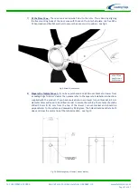
cables are snagged. Use the M6 x 70 Cap Heads along with two washers and an anti-
vibration nut to secure the turbine using the holes previously drilled and the hole in the
yaw pivot - see Fig-11. Ensure that M6 set-screws are securely fastened. Depending on the
exact dimension of the tower, it may be necessary to use the supplied shim plate to ensure
that the turbine is a snug fit upon the tower.
Fig-11: Fitting the turbine onto the support structure
M6 X 70 Cap Heads
Use Yaw Shim if mounting to
a 48.3mm Dia Pole
Summary of Contents for GA-LETU-016
Page 47: ......


