


12. PICTURE DISPLAY
122
12.8
Configuring Line Selection Settings
To configure line selection settings, press F•2 LINE SEL on the picture menu. The line
selection feature allows you to display a marker on the selected line.
The markers that you set here do not appear in thumbnail displays, the 2-channel display or
3D assist display (option).
F•2 LINE SEL appears when SIZE has been set to FIT.
For information on the SIZE setting, see section 12.9.1, “Setting the Display Size”
12.8.1
Turning Line Selection On and Off
To display a marker on the selected line, follow the procedure below.
Changing this setting will also change the video-signal-waveform-display and
vector-display line selection settings.
Procedure
PIC
→
F•7 next menu
→
F•2 LINE SEL
→
F•1 LINE SELECT
Settings
ON:
A marker appears on the selected line.
OFF:
A marker does not appear on the selected line (this is the default value).
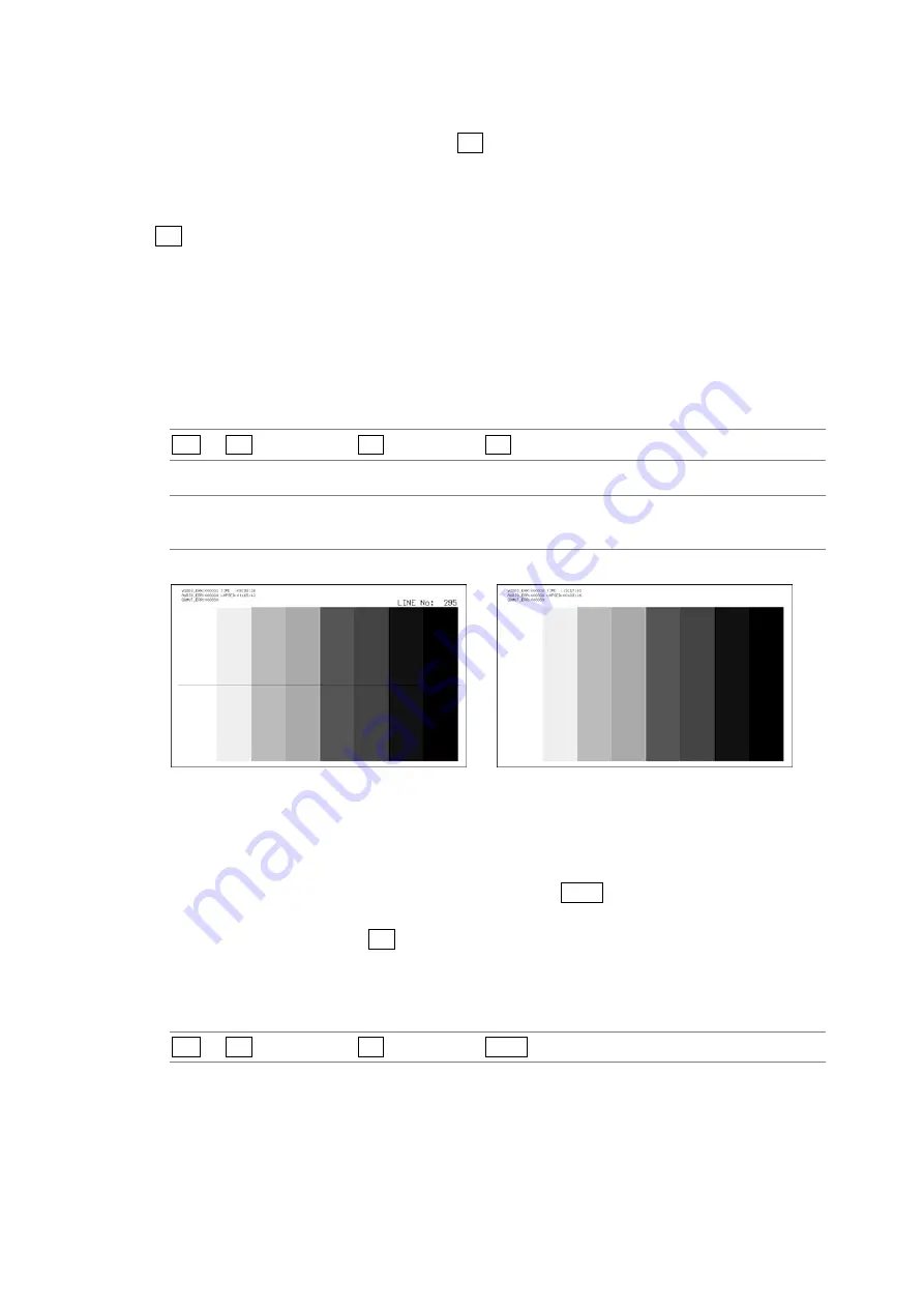
LINE SELECT = ON
LINE SELECT = OFF
Figure 12-8 Turning line selection on and off
12.8.2
Selecting Lines
To select a line to display a marker on, follow the procedure below. The selected line is
indicated in the upper right of the display. If you press F•D 1, the selected line changes to
the first video line.
You can select a line when F•1 LINE SELECT is set to ON. Changing this setting will also
change the selected line on the video-signal-waveform, vector, and status (data dump)
displays.
Procedure
PIC
→
F•7 next menu
→
F•2 LINE SEL
→
F•D 1 LINE VARIABLE


