Leader LV 7290 Instruction Manual Download Page 3

I


GENERAL SAFETY SUMMARY 

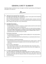
  Read This before Using the Instrument 

This instrument should only be used by persons with sufficient knowledge of electronics who 
thoroughly understand the contents of this manual. 


This instrument is not designed or manufactured for households or ordinary consumers. 
If unqualified personnel are to use the instrument, be sure the instrument is handled under the 
supervision of qualified personnel (those who have electrical knowledge). This is to prevent the 
possibility of personal injury or damage to the instrument. 

  Note about Reading This Manual 

The contents of this manual contain specialized terminology and may be difficult to understand. If 
you have any questions about the contents of this manual, please contact your local LEADER 
agent. 

  Symbols and Terms 

The following symbols and terms are used in this instruction manual and on the instrument to 
indicate important warnings and notes. 


<Symbol> 


This symbol appears in this instruction manual and on the instrument to 
indicate an area where improper handling could result in personal injury, 
damage to the instrument, or malfunction of the instrument or devices 
connected to it. 
When you encounter this symbol on the instrument, be sure to refer to the 
information in this instruction manual that corresponds to the area that the 
symbol marks. 

<Term> 


Ignoring the precautions that this term indicates could lead to death or 
serious injury. 

<Term> 


Ignoring the precautions that this term indicates could lead to personal injury 
or damage to the instrument. 

Summary of Contents for LV 7290

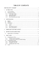
Page 1: ...LV 7290 REMOTE CONTROLLER INSTRUCTION MANUAL...

Page 2: ...ations 3 2 3 1 Control 3 2 3 2 Panel 4 2 3 3 Rear Panel Connectors 4 2 3 4 General Specifications 4 3 NAMES AND FUNCTIONS OF PARTS 5 4 BEFORE YOU BEGIN MEASURING 6 4 1 Attaching the Cover Inlet Stoppe...

Page 3: ...tand If you have any questions about the contents of this manual please contact your local LEADER agent Symbols and Terms The following symbols and terms are used in this instruction manual and on the...

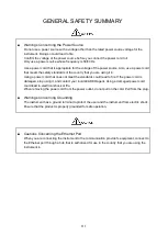
Page 4: ...ossibility that the instrument has condensation within it wait for approximately 30 minutes before turning on the power Operating Humidity Range Use this instrument in an environment whose relative hu...

Page 5: ...does not meet the standards could lead to fire If the power cord is damaged stop using it and contact your local LEADER agent Using a damaged power cord could lead to electrical shock or fire When rem...

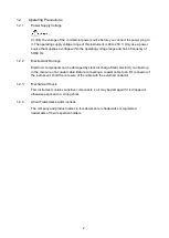
Page 6: ...h with mild detergent and wipe gently While cleaning make sure that foreign materials such as water and detergent do not enter the product If liquid or a metal object enters into the instrument fire o...

Page 7: ...cope of Warranty This LEADER instrument has been manufactured under the strictest quality control guidelines LEADER shall not be obligated to furnish the following free services during the warranty pe...

Page 8: ...Electronic components can be damaged by static discharge Static electricity can build up in the core wire of a coaxial cable Before connecting a coaxial cable to an I O connector of the instrument sh...

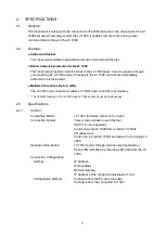
Page 9: ...ctions Up to 8 units The LV 7290 can connect to multiple LV 7390s and control them exclusively The TELNET features of the LV 7290 and LV 7390 cannot be used simultaneously 2 3 Specifications 2 3 1 Con...

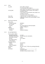
Page 10: ...r Panel Connectors Ethernet Port Compliant Standard IEEE802 3 I O Connector RJ 45 Functions Key code transmission LED data reception Type 10Base T 100Base TX USB Port Type B Specifications USB 2 0 Fun...

Page 11: ...the key lock 4 UNIT Selects the connection destination 5 ETHERNET Connected to the LV 7390 The LV 7390 is remotely controlled from this instrument through this port It also allows LV 7390 key operati...

Page 12: ...ollow the procedure below Attaching the Cover Inlet Stopper 1 Cover the power cord with the cover inlet stopper 2 Push the cover inlet stopper until you hear a click to attach it to the AC inlet 3 Che...

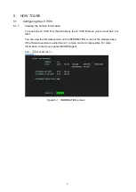
Page 13: ...rument the LV 7390 firmware version must be 2 0 or later You can view the firmware version on the INFORMATION screen or the startup screen If the firmware version is earlier than 2 0 remote control is...

Page 14: ...to 192 168 0 1 If you use the factory default setting you will not need to carry out the procedure in section 5 2 Configuring the LV 7290 If you are going to connect the LV 7390 and LV 7290 in a one...

Page 15: ...e case proceed to section 5 3 Control 5 2 1 Factory Default Settings The factory default settings of this instrument are as follows Table 5 1 Factory default settings Parameter Factory default value I...

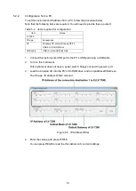
Page 16: ...indows7 8 10 USB2 0 CD ROM drive USB cable USB A male USB B male 1 Connect this instrument s USB port to the PC s USB port using a USB cable 2 Turn on this instrument This instrument does not have a p...

Page 17: ...the connection between this instrument and the LV 7390 is established Figure 5 5 LV7290 screen SETUP 2 Enter the values This instrument s settings are shown under Remote Controller and the connection...

Page 18: ...hts If it doesn t check section 5 1 Configuring the LV 7390 and 5 2 Configuring the LV 7290 again Note that the ETHERNET LED remains lit for a while even after the Ethernet cable is removed Control Wh...

Page 19: ...Following information is for Chinese RoHS only LV 7290 2006 2 28 SJ T11364 2006 Hazardous Substances in each Part Parts Pb Hg Cd Cr PBB PBDE SJ T11363 2006 SJ T11363 2006 Ver 1...

Page 20: ...LEADER ELECTRONICS CORP 2 6 33 Tsunashima Higashi Kohoku ku Yokohama 223 8505 Japan PHONE 81 45 541 2123 FAX 81 45 541 2823 http www leader co jp JAN 12 2017 Ver 1...

Reviews: