143
13. STATUS DISPLAY
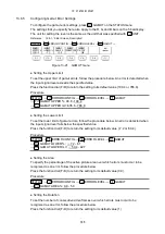
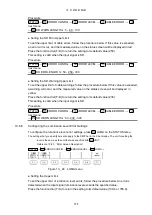
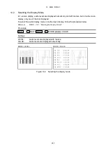
STATUS → F•4 ANC PACKET → F•4 V-ANC SMPTE → F•5 VBI
F•5
13.5.9
Displaying VBI Data
When the input signal is SD or HD, to display VBI data, follow the procedure below.
Procedure
Figure 13-18 Displaying VBI data
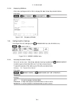
13.6 Configuring Error Settings
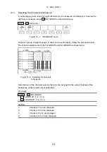
To configure the error settings, press
ERROR CONFIG on the STATUS menu.
→
ERROR CONFIG →
Figure 13-19 ERROR CONFIG menu
13.6.1
Selecting the Alarm Polarity
If an error occurs in an item whose detection has been enabled with
an alarm signal is transmitted from pin 14 of the remote connector.
To select the polarity of the alarm signal, follow the procedure below.
Reference 16.1, “Remote Control Feature”
ERROR DETECT,
Procedure
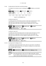
STATUS → F•5 ERROR CONFIG → F•1 REMOTE ERR OUT: OFF / POSITIVE /
NEGATIVE
Settings
OFF:
An alarm signal is not transmitted.
POSITIVE: A high level signal is transmitted when an error occurs.
NEGATIVE: A low level signal is transmitted when an error occurs.
F•5
F•3
STATUS


