PDU6M MANUAL V0.1
9
Luci della Ribalta srl - Via Berna 14, Z.I. Bosco dell’Irta, 46042 Castel Goffredo MN, Italy
tel. +39 0376 771 777 - fax +39 0376 772 140 - email [email protected] - web www.ldr.it
Page 08 of 22
ENGLISH
7.3
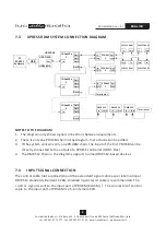
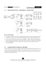
XPRESS RDM SYSTEM CONNECTION DIAGRAM
NOTES TO THE DIAGRAM
1. The diagram only shows signal connections between equipments
2.
The control cable (not supplied) should be a standard signal cable as per international
DMX512 standards. Belden 1420A, shielded 3 pairs twist cable is recommended.
7.4
INPUT SIGNAL CONNECTION
There is only one PDU6M chain in the diagram, more chains can be added.
3. If the system contains only one PDU6M chain, the input of the first PDU6M can be
directly connected to the output of a XPRESS controller (UDM- Box)
4. The DMX512 chain in the diagram supports normal DMX512-based devices
. The connector of control
cable to
The
control signal is sent to the input port of PDU6M (XLR5M) )
the input port of PDU6M is a 5-pin female XLR.
In
In
In
In
Thru
Thru
Thru
Thru
Terminator
Terminator
DMX 512
In
Thru
DMX 512
In
Thru
DMX 512
In
Thru
OUT
XPRESS RDM
Out
Loop
In
Thru
PDU6M
1
Out
Loop
In
Thru
PDU6M
2
Out
Loop
In
Thru
PDU6M
Y
XPRESS RDM
XPRESS RDM
XPRESS RDM
Out 1
Out 2
Out 3
Out N
In
IDAxxMx
X
Out 1
Out 2
Out 3
Out N
In
IDAxxMx
2
Out 1
Out 2
Out 3
Out N
In
IDAxxMx
1
PC
XPRESS
Software
USB
USB-DMX
UDM BOX
UDM BOX


