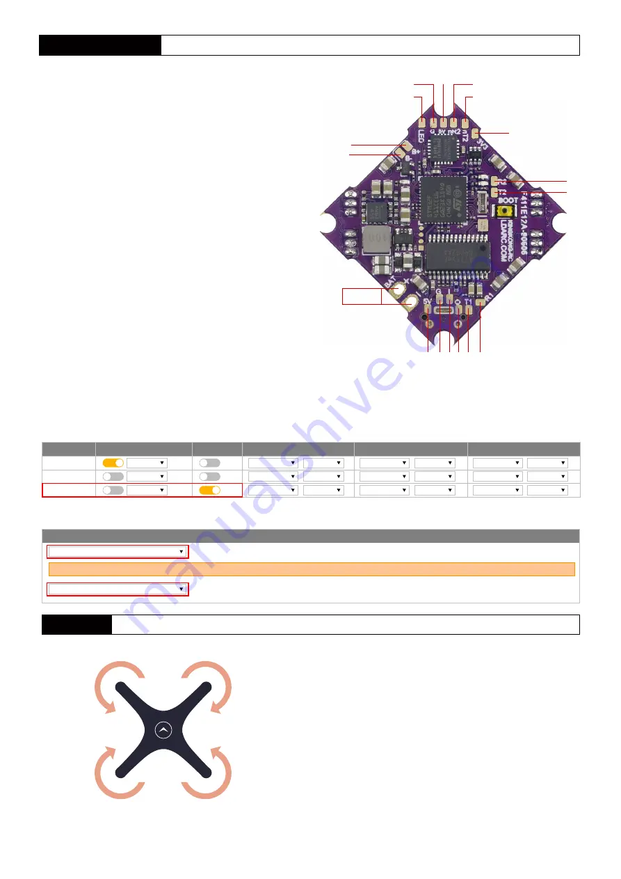
background image

-2-

M4(CW)

M2(CCW)

M3(CCW)

Pay attention to  the direction of rotation of the motor when installing the prop

M1(CW)

Motor

UART setting

Receiver setting

Identifier

USB VCP
UART1
UART2

Configuration/MSP

115200

Serial RX

Telemetry Output

Disabled

AUTO

Sensor Input

Peripherals

Disabled

AUTO

Disabled

AUTO

Disabled

AUTO

Disabled

AUTO

Disabled

AUTO

Disabled

AUTO
AUTO

Disabled

Disabled

AUTO

115200
115200

Receiver

Serial-based receiver(SPEKSAT

Receiver Mode

SBUS

Serial Receiver Provider

Note : Remember to configure a serial Port(via Ports tab) and choose a Serial Receiver Provider when using RX_SERIAL feature

LED

G

5V

+5V

GND Video in Video out TX1 IR

C T
ramp

RX1

2-4S

Invert RX2

Invert TX2

3V3

Buzzer-

R2

T2

F411E12A 

parameters

  <1> STM32F411 MCU,Operation at 100Mhz,firmware target MATEKF411.
  <2> MPU-6000 six-axis SPI sensor.
  <3> Low power version AT7456E,support Betaflight OSD. 
  <4> BEC use MP9943 High-Efficiency Synchronous mode DC-DC,
          support [email protected] output. 
  <5> TX1 and RX1 pads,can support IRC-Tramp or Camera control.


<6> UART2 have 4 pads, TX2, RX2, invert TX2, invert RX2, support

          all type receiver, like S.BUS, DSM, iBUS, F.Port, crossfire etc.

  <7> TX2 and RX2 pads,RX2 support NOT invert receiver,for example 
          DSM or iBUS.
  <8> Invert TX2 and invert RX2 pads,invert RX2 support invert receiver 
          like S.BUS,and PPM receiver also need connect to invert RX2 pad.
  <9> Support buzzer and LED strip.
<10> Onboard current sensor,current scale value 210.
<11> BLheli_S four in one ESC,target is G-H-30.
<12> ESC maximum current 12A each way,support 2S~4S lipo battery,


if use 2S battery please make sure voltage not lower than 6.8V 

          when ESC in heavy load.

Summary of Contents for ET85D PNP

Page 1: ...ET85D Manual ET85D PNP Manual 200430 User manual and video please visit WWW LDARC COM PRODUCT Multirotor ET Series ET85D PNP ...

Page 2: ...mm Camera angle 15 45 Mounting size FC 25 5 25 5mm Motor Φ9mm M2 7 Camera 19mm 20mm Configuration FC ESC F411E12A DJI Digital FPV System Motor XT1105 4250KV Prop 2045 4blade Recommend Battery LDARC 14 8V 430mAh XT30 Need buy another Note Drone weight not include receiver and battery Package list ET85D DJI Digital FPV System 1 2045 4blade 10pairs Rack 6 Sticker 2 ST1 2 4 4 ST1 4 10 4 ET85D 1 2045 4...

Page 3: ...2 F411E12A parameters 1 STM32F411 MCU Operation at 100Mhz firmware target MATEKF411 2 MPU 6000 six axis SPI sensor 3 Low power version AT7456E support Betaflight OSD 4 BEC use MP9943 High Efficiency Synchronous mode DC DC support 5V 1 5A output 5 TX1 and RX1 pads can support IRC Tramp or Camera control 6 UART2 have 4 pads TX2 RX2 invert TX2 invert RX2 support all type receiver like S BUS DSM iBUS ...

Page 4: ...Digital FPV System DJI Digital FPV system install 1 Open canopy connect DJI Digital FPV Sytem 3 Stick EVA 4 Use screw install canopy 2 Install DJI Digital FPV Sytem DJI HDL GND TX RX 7 4 17 6V GND nR2 BAT BAT R1 T1 ...

Page 5: ... and FC together 2 Use ST1 4 4 screw install FC and Vista rack 3 Use ST1 4 10 screw install Vista Caddx Vista install ET85D Caddx VISTA 4 Use M2 4 screw install camera then install canopy Caddx VISTA SBUS TX RX G 7 4 26 4V nR2 G T1 R1 VCC G ...

Page 6: ...key green LED fast blink meaning already in bind mode user can release the key Bind procedure is completed and the receiver is working normally when green LED is solid FRSKY D16 NO Telemetry BIND Power on AC900 while pressing the key green LED fast blink meaning already in bind mode user can release the key then set your TX into D16 bind mode red LED solid meaning bind finished exit TX from bind m...

Page 7: ...st blink meaning already in bind mode user can release the key then set your TX into bind mode Green LED turn off and red LED solid mean bind finished exit TX from bind mode receiver sgreen LED solid mean working normally RX2A PRO Bind S BUS transmitter FLYSKY FS i6 ...

Page 8: ...GHT firmware allready flash before leave the factory user just need connect PC to adjust the parameter 1 Open betaflight configuration then click select FW version Firmware Update Connect 2 Click then click to download FW to FC click after FW updating finish into setting menu 3 Calibration Calibrate Accelerometer ...

Page 9: ... 9 6 PID Setting ...

Page 10: ... 10 7 Mode setting ...

Page 11: ...ind the product defect after purchase 2 Provide pay needed reparation service when product damage because improper operation 3 China customers please contact with the after sales service overseas client please contact the dealer PNP RTF Test report ID Flight test Transmitter functions properly Flying in good condition Camera OK VTX OK QC Package check PNP RTF Frame Transmitter ID is the same All p...

Reviews: